Note: Descriptions are shown in the official language in which they were submitted.
CA 02378736 2002-01-09
WO 01/04680 PCTIUSOO/18998
APPLICATION FOR PATENT
Title: MICRO-MACHINED MIRROR DEVICE
Background of the Invention
This invention relates generally to micro-machined three-dimensional
structures, and in particular to micro-machined mirrors for use in optical
readers, such as bar code readers or scanners.
Conventional bar code scanners are used to scan a surface with a
laser beam. Conventional bar code scanners further typically utilize mirrors
that are oscillated to permit the laser beam to scan. Conventional mirrors for
bar code scanners are relatively large and imprecise.
In order to manufacture smaller and more precise bar code mirrors,
micro-machining processes have been used in which a silicon substrate is
micro-machined to produce a mirror. However, conventional micro-machined
mirrors and their manufacturing processes suffer from a number of limitations.
Prior art micro-machined mirrors do not provide appropriate compliance in all
directions of the movement of the mirror. Such mirrors typically are not
sufficiently shock resistant or able to operate over wide ranges of
temperature
over extended use.
The present invention provides micro-machined mirror devices which
overcome one or more limitations of the existing micro-machined devices.
CA 02378736 2009-12-18
Summary of the Invention
According to one aspect of the present invention, a mirror assembly is
provided that includes a mirror, a top cap, and a bottom cap. The mirror
includes a mirror support structure, a pair of T-shaped hinges coupled to the
mirror support structure and a mirrored plate coupled to the T-shaped hinges.
The mirrored plate includes one or more travel stops for limiting movement of
the mirrored plate. The top cap is coupled to one side of the mirror. The
top cap includes a top cap support structure that includes an opening for
permitting light to reflect off of the mirrored plate and one or more travel
stops
coupled to the top cap support structure for limiting movement of the mirrored
plate. The bottom cap is coupled to another side of the mirror. The
bottom cap includes a bottom cap support structure including an opening and
one or more travel stops coupled to the bottom cap support structure for
limiting movement of the mirrored plate.
According to another aspect of the present invention, a mirror
assembly is provided that includes a support structure, pair of T-shaped
hinges coupled to the support structure and a mirrored plate coupled to the T-
shaped hinges. The mirrored plate includes one or more travel stops for
limiting movement of the mirrored plate.
According to another aspect of the present invention, an apparatus is
provided that includes a housing, a mass, and one or more springs for
coupling the mass to the housing. Each spring includes a rotational spring
constant and a translational spring constant. The rotational spring constant
is
decoupled from the translational spring constant.
-2-
WO 01/04680 CA 02378736 2002-01-09 PCTIUSOO/18998
According to another aspect of the present invention, a method of
resiliently supporting a mass in a housing is provided that includes coupling
the mass to the housing using one or more hinges having translational spring
constants and rotational spring constants and decoupling the translational
spring constants from the rotational spring constants.
According to another aspect of the present invention, a method of
resiliently supporting a mass in a housing is provided that includes limiting
translational movement of the mass in the X, Y and Z directions and limiting
rotational or torsional movement of the mass.
According to another aspect of the present invention, an apparatus is
provided that includes a housing and a mass resiliently coupled to the
housing. The mass includes one or more travel stops for limiting rotational
and translational or planar movement of the mass.
According to another aspect of the present invention, a method of
reflecting rays of light is provided that includes a reflective surface and
providing an optical pathway for accessing the reflective surface or planar
one
or more cutouts for minimizing clipping of the incident and reflected light
rays.
Brief Description of the Drawings
FIG. I is a cross section view of a laser scanning device according to
the present invention.
FIG. 2 is a schematic side view of a preferred embodiment of the
mirror assembly of FIG. 1.
FIG. 3 is a top view of the top cap of the mirror assembly of FIG. 2.
FIG. 4 is a cross-sectional view of the top cap of FIG.3.
-3-
CA 02378736 2002-01-09
WO 01/04680 PCT/US00/18998
FIG. 5 is a cross-sectional view of the top cap of FIG. 3.
FIG. 6 is a top view of the mirror of the mirror assembly of FIG. 2.
FIG. 6A is a top view of an alternative embodiment of the hinge of the
mirror assembly of FIG. 2.
FIG. 6B is a top view of an alternative embodiment of the hinge of the
mirror assembly of FIG. 2.
FIG. 6C is a top view of an alternative embodiment of the hinge of the
mirror assembly of FIG. 2.
FIG. 6D is a top view of an alternative embodiment of the mirror of the
mirror assembly of FIG. 2.
FIG. 7 is a cross-sectional view of the mirror of FIG. 6.
FIG. 8 is a cross-sectional view of the mirror of FIG. 6.
FIG. 9 is a bottom view of the mirror of FIG. 6.
FIG. 10 is a top view of the bottom cap of the mirror assembly of FIG.
2.
FIG. 11 is a cross-sectional view of the bottom cap of FIG. 10.
FIG. 12 is a cross-sectional view of the bottom cap of FIG. 10.
FIG. 13 is a top view of the base member of the mirror assembly of
FIG. 2.
FIG. 14 is a cross-sectional view of the base member of FIG. 13.
FIG. 15 is a cross-sectional view of the base member of FIG. 13.
FIG. 16 is a top view of the top cap and mirror of the mirror assembly
of FIG. 2.
-4-
WO 01/04680 CA 02378736 2002-01-09 pCT/US00/18998
FIG. 17 is a top view of the bottom cap and base member of the mirror
assembly of FIG. 2.
FIG. 18 is a cross-sectional view of the mirror assembly of FIG. 16
illustrating the oscillation of the mirror collection plate.
FIG. 19 is a view of the mirror assembly of FIG. 18 illustrating the use
of tapered surfaces to minimize clipping of the laser light.
Detailed Description of the Preferred Embodiments
A mirror assembly for use in a bar code reader is provided. The mirror
assembly preferably includes a micro-machined three-dimensional mirror
supported generally by a pair of "T" shaped hinges in a support structure.
The mirror assembly further preferably includes one or more travel stops for
limiting the movement of the mirror. The mirror assembly further preferably
includes one or more tapered edge surfaces and cut-outs for minimizing
clipping of incident and reflected laser beams.
FIG. 1 is a cross section view of a laser scanning device such as a bar
code scanner 100 having a light beam 115 that emanates from the device to
strike a target 120. The light beam is reflected or scattered by the target
120.
The bar code scanner 100 includes a laser beam source 105 and a mirror
assembly 110. During the operation of the bar code scanner 100, the
optically reflective portion 111 of the mirror assembly 110 is preferably
oscillated to permit the laser beam 115 to scan a surface, such as a bar code
symbol 120, by reflecting the laser beam 115 off of the optically reflective
portion 111 of the mirror assembly 110. The reflected light 125 enters the bar
-5-
WO 01/04680 CA 02378736 2002-01-09 PCTIUSOO/18998
code scanner 100 through a window 165 and is detected by a light detector
160. The laser beam source 105 may comprise any number of conventional
commercially available devices to generate the laser beam 115.
The bar code scanner 100 may include additional features for user
interface, control and data processing. These features may comprise a
processor 130 and memory device 135 as part of a central processing unit
140, a controller 145 for generating voltage used to oscillate the mirror 110,
a
data entry device such as a keypad 150 and a data display device such as a
liquid crystal display 155. The mirror assembly 110 made according to the
present invention is described below in reference to FIGS. 2-19.
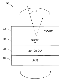
Referring to FIG. 2, in a preferred embodiment, the mirror assembly
110 includes a top cap 205, a mirror 210, a bottom cap 215, and a base
member 220. The top cap 205 includes an opening that permits the laser
beam 115 to reflect off of the mirror 210. In this manner, the mirror 210 is
surrounded and protected by the top cap 205 and the bottom cap 215. The
sub-assembly that includes the top cap 205, mirror 210 and bottom cap 215 is
formed and then mounted onto the base member 220.
The top cap 205 and bottom cap 215 may be fabricated from any
number of conventional commercially available materials such as, for
example, silicon glass, ceramic or plastic. In a preferred embodiment, the top
cap 205 is fabricated by micro-machining a silicon wafer.
FIGS. 3-5 show various views of a preferred embodiment of the top
cap 205 which has a frame 301 that includes a top, bottom, left and right
support members 305, 315, 325 and 335. Top and bottom travel stop
-6-
CA 02378736 2002-01-09
WO 01/04680 PCTIUSOO/18998
members 310 and 320 are coupled respectively to the top and bottom support
members 305 and 315. The left and right support members 325 and 335
include corresponding left and right rim cutouts 330 and 340 for minimizing
clipping of the incident light.
The top cap frame 301 provides an overall support structure for the top
cap 205. The thickness of the frame 301 may range, for example, from about
400 to 600 microns with a preferred thickness ranging from about 390 to 400
microns in order to provide a compact structure having a low mass.
The top travel stop 310 preferably limits the motion of the reflective
portion of the mirror 210 in the direction normal to the plane of the
reflective
portion of the mirror 210 (the Z-direction). The top travel stop 310
preferably
extends in substantially orthogonal direction from the top support member
305. In a preferred embodiment, the top travel stop 310 is positioned within
the plane of the top support member 305. The thickness of the top travel stop
310 may range, for example, from about 340 to 580 microns. In a preferred
embodiment, the thickness of the top travel stop 310 ranges from about 350
to 380 microns in order to provide optimum shock protection, freedom of
motion, and a compact structure having a low mass.
Referring to FIG. 4, in a particularly preferred embodiment, the bottom
surface 310b of the top travel stop 310 is recessed below the level of the
bottom surface 305b of the top support member 305. In this manner, the
bottom surface 310b of the top travel stop 310 is preferably positioned above
the level of the reflective surface of the mirror 210. The length of the top
travel stop member 310 may range, for example, from about 800 to 2800
-7-
CA 02378736 2002-01-09
WO 01/04680 PCT/USOO/18998
microns. In a preferred embodiment, the length of the top travel stop member
310 ranges from about 2000 to 2500 microns. In a particularly preferred
embodiment, the length of the top travel stop member 310 is selected to
overlap with the mirror collection plate 610 of the mirror by about 300
microns.
The bottom travel stop 320 extends in a substantially orthogonal
direction from the bottom support member 315 and is substantially identical to
the top travel stop 310. An opening 345 permits light to reflect off of the
reflective surface of the mirror 210. The opening 345 preferably includes a
left rim cut out 330 and a right rim cut out 340. The left and right rim cut
outs,
330 and 340, are preferably positioned on opposite sides in surrounding
relation to the reflective surface of the mirror 210. In this manner, the left
and
right rim cut-outs, 330 and 340, provide optical access to the reflective
surface of the mirror 210.
In a preferred embodiment, the top cap frame 301, travel stops 310
and 320, rim cut outs 330 and 340, and the opening 345 all include tapered
edges, 350A and 350B, to facilitate optical access to the reflective surface
of
the mirror 210 (FIG. 5). The taper angle of the tapered edges, 350A and
350B, preferably ranges from about 50 to 60 degrees in order to optimally
facilitate the reflection of laser light transmitted at an angle towards the
edge
portions of the reflective surface of the mirror 210.
FIG. 6 shows a top view of a mirror or mirror assembly 210 made
according to one embodiment of the present invention. The mirror 210
includes a frame or mirror support structure 600 having support members
-8-
WO 01/04680 CA 02378736 2002-01-09 pCT/US00/18998
602, 604, 606 and 608. The mirror 210 further comprises a mirror collection
plate 610 with a reflective surface 628, a top T-shaped hinge 612, a bottom T-
shaped hinge 614, a top left travel stop finger 616, a top right travel stop
finger 618, a bottom left travel stop finger 620, a bottom right travel stop
finger
622, an opening 624, a conductive layer 626, and a reflective surface 628.
The mirror frame 600 provides the overall support structure for the
mirror 210. The thickness of the frame 600 may range, for example, from
about 400 to 600 microns with a preferred thickness ranging from about 400
to 450 microns in order to provide a compact structure having a low mass. In
a preferred embodiment, the support members 602, 604, 606, and 608
provide effective beam lengths ranging from about 500-2500 microns and
cross sections of about 8,000 microns2 to 160,000 micronsz in order to
optimally absorb shock loads of about 2000g/0.5 mS half sine wave input.
The mirror collection plate 610 is coupled to the top T-shaped hinge
612 and the bottom T-shaped hinge 614. In this manner, the mirror collection
plate 610 rotates about the axis 630 i.e. has torsional movement about such
axis. In a preferred embodiment, the axis 630 is positioned substantially
along the centerline of the mirror collection plate 610 and is coincident with
the center of the T-shaped hinges, 612 and 614, thereby providing a common
axis of rotation for the springs. The reflective surface 628 is coupled to the
top 632 of the mirror collection plate 610. In this manner, rotation of the
mirror collection plate 610 about the axis 630 causes laser light from a
stationary laser to reflect off of the reflective surface 628 in a plurality
of
directions.
-9-
CA 02378736 2002-01-09
WO 01/04680 PCTIUSOO/18998
The thickness of the mirror collection plate 610 may range, for
example, from about 100 to 600 microns with a preferred thickness ranging
from about 100 to 250 microns to provide a low mass and maximize the
effective natural frequency of the mirror 210.
The reflective surface 628 may be comprised of any number of
conventional commercially available optically reflective surfaces such as, for
example, gold, silver or aluminum. In a preferred embodiment, the reflective
surface 628 comprises gold in order to optimize the amount of optical energy
that is reflected. In a preferred embodiment, the surface roughness of the
reflective surface 628 is less than about 0.1 wavelengths of the reflected
light
in order to optimize the amount of optical energy that is reflected.
The FIGS. 7 and 8 show cross-sectional views of the mirror of FIG. 6
and FIG. 9 shows a bottom view of the mirror of FIG. 6. As illustrated in
FIGS. 7-9, in a preferred embodiment, the bottom 634 of the mirror collection
plate 610 includes a top travel stop 710, a bottom travel stop 715, and a
cavity 720. The top travel stop 710 extends from the bottom 634 of the
mirror collection plate 610. The top travel stop 710 preferably limits
movement of the mirror collection plate 610 in the z-direction. The top travel
stop 710 preferably extends from the bottom 634 of the mirror collection
piate 610 in a substantially orthogonal direction. The top travel stop 710 may
extend from the bottom 634 of the mirror collection plate 610 for a distance
ranging, for example, from about 200 to 400 microns with a preferred
distance ranging from about 200 to 250 microns to optimally limit movement
of the mirror collection plate 610. In a preferred embodiment, the top travel
-10-
CA 02378736 2002-01-09
WO 01/04680 PCT/US00/18998
stop 710 is centered about the axis 630 and is positioned adjacent to and on
one side of the cavity 720. The bottom travel stop 715 is preferably identical
to the top travel stop 710 described above.
The cavity 720 extends into the bottom of the mirror collection plate
610, which reduces the mass of the mirror collection plate 610. In this
manner, the droop of the mirror 210 is reduced. In a preferred embodiment,
the depth and volume of the cavity 720 ranges from about 200 to 500
microns and 8X10⁶ to 1X10⁹ microns.3 In a preferred embodiment, the
cavity 720 is centrally positioned along the axis 630 and within the back side
634 of the mirror collection plate 610.
For typical bar code scanner applications, the rotational accuracy of
the laser beam may be required to be within 1.30 when the mirror collection
plate 610 is subjected to an across-the-hinge self-induced gravity torque.
Where torque T = mg*h/2, with mg = mirror collection plate weight and h
mirror collection plate thickness. The mirror accuracy is a function of the
pointing accuracy and mirror droop. The torsional spring constant Kr of the
T-shaped hinges, 612 and 614, is determined by the resonant frequency F of
the mirror collection plate 610 and the size and mass of the mirror collection
plate 610. The mirror tilt angle 6 due to a gravity torque is determined by
the
relation, 6=T/Kr. Consequently, the thickness and mass of the mirror
collection plate 610, are preferably selected to provide a mirror tilt angle
less
than 1.3 . In a preferred embodiment, the thickness and mass of the mirror
collection plate 610 are reduced by reducing the thickness of the mirror
-11-
CA 02378736 2002-01-09
WO 01/04680 PCTIUSOO/18998
collection plate 610 and by providing one or more cavities in the mirror
collection plate 610.
The top T-shaped hinge 612 is coupled to the left support member
606, the right support member 608, and the top portion of the mirror
collection plate 610. The top T-shaped hinge 612 preferably includes a
vertical support member 644 (beam or leg) and a second or horizontal
support member 646 (T-member). The horizontal support member 646
preferably is supported at opposite ends by the left support member 606 and
the right support member 608. In a preferred embodiment, the horizontal
support member 646 is substantially orthogonal to both the left support
member 606 and the right support member 608. The vertical support
member 644 is coupled to the horizontal support member 646. In a
preferred embodiment, the vertical support member 644 is substantially
orthogonal to the horizontal support member 646. The vertical support
member 644 is coupled to the mid-point of the horizontal support member
646. The vertical support member 644 is positioned along the axis 630. The
length, width and thickness of the vertical support member 644 may range,
for example, from about 100 to 2500 microns, 2 to 100 microns and 2 to 100
microns, respectively. In a preferred embodiment, the length, width and
thickness of the vertical support member 644 range from about 800 to 1000
microns, 8 to 15 microns and 8 to 15 microns, respectively. The torsional
spring constant of the vertical support member 644 may range, for example,
from about 2x10' to 10x10-' Ibf-ft/radian. In a preferred embodiment, the
torsional spring constant of the vertical support member 644 ranges from
-12-
CA 02378736 2002-01-09
WO 01/04680 PCT/US00/18998
about 2x10-$ to 10x10' Ibf-ft/radian. The length, width and thickness of the
horizontal support member 646 may range, for example, from about 500 to
4500 microns, 6 to 100 microns and 6 to 100 microns, respectively. In a
preferred embodiment, the length, width and thickness of the horizontal
support member 646 range from about 2200 to 2500 microns, 15 to 25
microns and 15 to 25 microns, respectively.
The bottom T-shaped hinge 614 is coupled to the left support member
606, the right support member 608, and the bottom portion of the mirror
collection plate 610. The bottom T-shaped hinge 614 has the same
structure as the top T-shaped hinge 612.
Other embodiments of a T-shaped hinge according to the present
invention, as illustrated in FIGS. 6A-6C, provide enhanced sensitivity for
sensing acceleration loading conditions. In FIG. 6A, a T-shaped hinge 612A
includes a vertical support member 644A having a serpentine shape and a
horizontal support member 646A having a substantially linear shape. In FIG.
6B, an alternative embodiment of a T-shaped hinge 612B includes a vertical
support member 644B coupled to a horizontal support member 646B at
location that is off-center. In FIG. 6C, one or both of the T-shaped hinges
612 and 614 are modified to include a T-shaped hinge 612C having a
vertical support member 644C that intersects a horizontal support member
646C at an acute angle and is also coupled to the horizontal support
member 646C at location that is off-center.
The top left travel stop 616 extends from and is coupled to the top left
portion of the mirror collection plate 610. The top left travel stop 616
-13-
WO 01/04680 CA 02378736 2002-01-09 PCTIUSOO/18998
preferably limits the motion of the mirror collection plate 610 in the x-
direction. The top left travel stop 616 preferably is positioned in the plane
of
the mirror collection plate 610. In a preferred embodiment, the top left
travel
stop 616 extends from the mirror collection plate 610 in a substantially
orthogonal direction. The thickness of the top left travel stop 616 may range,
for example, from about 200 to 600 microns. In a preferred embodiment, the
thickness of the top left travel stop 616 ranges from about 250 to 350
microns in order to optimally provide shock protection, and a resilient
compact structure having a low mass. The length of the top left travel stop
616 may range, for example, from about 500 to 2000 microns. In a preferred
embodiment, the length of the top left travel stop 616 ranges from about 900
to 1100 microns. In a particularly preferred embodiment, the top surface of
the top left travel stop 616 is planar with the top surface of the mirror
collection plate 610. In a particularly preferred embodiment, the bottom
surface of the top left travel stop 616 is planar with the bottom surface of
the
mirror collection plate 610.
The top right and bottom left and right travel stops 618, 620 and 622
are substantially identical to the top left travel stop 616. These travel
stops
are positioned in corresponding locations about the mirror collection plate
610.
The travel stops, 616, 618, 620 and 622, preferably provide overswing
and x-axis shock protection for the mirror collection plate 610 during
manufacturing and operation. In a preferred embodiment, the travel stops
616, 618, 620, and 622 are formed as integral parts of the mirror collection
-14-
CA 02378736 2002-01-09
WO 01/04680 PCT/US00/18998
plate 610. In a preferred embodiment, the travel stops 616, 618, 620, and
622 provide effective beam lengths greater than about 500 microns and
cross sections of about 40,000 microns2 to 240,000 microns2 in order to
optimally absorb shock loads of about 2000g/0.5 mS half sine wave input.
The opening 624 preferably permits the mirror collection plate 610 to
rotate about the axis 630. The walls 636 of the opening 624 preferably limit
movement of the mirror collection plate 610 in the x-direction and the y-
directions. The opening 624 preferably includes a top section 638, a middle
section 640, and a bottom section 642. The top section 638 of the opening
624 preferably contains the top T-shaped hinge 612 and the top left and right
travel stops, 616 and 618. The middle section 640 of the opening 624
preferably contains the mirror collection plate 610. The bottom section 642
of the opening 624 preferably contains the bottom T-shaped hinge 614 and
the bottom left and right travel stops, 620 and 622.
The walls of the middle section 640 of the opening 624 may be
spaced apart from the opposing edges of the mirror collection plate 610 by a
distance ranging, for example, from about 30 to 150 microns. In a preferred
embodiment, the walls of the middle section 640 of the opening 624 are
spaced apart from the opposing edges of the mirror collection plate 610 by a
distance ranging from about 60 to 100 microns in order to optimally minimize
movement of the mirror collection plate 610 in the x and y directions. In a
preferred embodiment, the gap in the x-direction is different from the gap in
the y-direction in order to optimally protect the mirror collection plate 610
from shocks. In a preferred embodiment, the gap between the mirror
-15-
CA 02378736 2002-01-09
WO 01/04680 PCT/US00/18998
collection plate 610 and the middle section 640 of the opening 624 provides
a spacing in the y-direction ranging from about 15 to 45 microns and a
spacing in the x-direction ranging from about 50 to 180 microns in order to
optimally limit shock loads on the mirror collection plate 610.
The conductive layer 626 is preferably coupled to the outer periphery
of the top surface of the mirror 210. The conductive surface 626 preferably
provides a conductive electrical path. The conductive layer 626 may be
fabricated from any number of conventional commercially available materials
such as, for example, gold, aluminum, or silver. In a preferred embodiment,
the conductive layer 626 is fabricated from gold. In a preferred embodiment,
the conductive layer 626 is bonded to the underlying substrate by an
intermediate layer of titanium.
The mirror 210 may be fabricated from any number of conventional
commercially available materials such as, for example, silicon, plated metal
or plastic. In a preferred embodiment, the mirror 210 is fabricated by micro-
machining a silicon wafer using any one, or combination, of the known micro-
machining processes.
In a preferred embodiment, the released and free-standing mirror
collection plate 610 is connected to the surrounding support frame, 600 by
the T-shaped hinges, 612 and 614. In a preferred embodiment, the travel
stop fingers, 616, 618, 620 and 622, provide overswing protection for the
mirror collection plate 610. In a preferred embodiment, a 200-micron deep
anisotropic deep reactive ion etching (DRIE) process is used to form very
precise, narrow gaps for X-axis shock protection and Y-axis shock protection,
-16-
CA 02378736 2002-01-09
WO 01/04680 PCTIUSOO/18998
where the mirror collection plate 610 is preferably completely confined within
the frame, 602, 604, 606 and 608, for X-axis and Y-axis translational or
planar motion i.e. in the planes of the mirrored surface. Persons having
ordinary skill in the art and the benefit of the present disclosure will
recognize
that the term DRIE refers to deep reactive ion etching of a substrate. In a
preferred implementation, the DRIE process is provided substantially as
disclosed in United States Patent Nos. 5,498,312 and 5,501,893, which are
incorporated herein by reference. The T-shaped hinges, 612 and 614,
preferably provide the collection plate 610 with optimal translational motion
in
X-axis and Y-axis directions, in which the mirror collection plate 610 is
shock-
stopped by the frame, 602, 604, 606 and 608, while also simultaneously
maintaining low stress levels within the T-shaped hinges, 612 and 614, to
avoid fracture. In a preferred embodiment, the T-shape hinges, 612 and
614, are relatively compliant in the X-axis and Y-axis directions, while they
are sufficiently rigid for rotational motion about the axis 630 for
establishing
the resonant frequency of the mirror collection plate 610.
Thus, in a preferred embodiment of the present invention, the mirror
collection plate 610 is supported and suspended by a pair of hinges 612 and
614. These hinges permit torsional movement or rotation of the mirror
collection plate 610 about the common hinge axis 630 and movement of the
mirror collection in each of the x, y and z direction. The gap or space 648
between the mirror plate 610 and the frame 601 in the y-direction permits
movement of the mirror collection plate 610 in the y-direction while the
spacing 611 between the stops 616, 618, 620 and 621 and the frame 601
-17-
CA 02378736 2002-01-09
WO 01/04680 PCT/US00/18998
permit movement in the x-direction. The gap 647 provides a hinge
compliance in the y-direction. The movements in the x and y directions are
sometimes referred to the planar or translational movements and the hinges
as springs. The beams 644 and 628 also permit the mirror collection plate
610 to move in the z-direction. The T-hinges provide the necessary
compliance to the mirror collection plate motion in the y-direction, which
improves the shock tolerance of the hinge to y-axis shock loads generated
by the mirror collection plate 610. Prior art typically utilizes a straight-
beam
hinge, i.e. a beam connected to the frame without a T-member, such as the
member 646. Such straight-beam hinges tend to buckle and fracture due to
y-axis shock loads. Also, the beams or legs 644 and 648 of the T-hinges
612 and 614 move up in the z-direction due to shock loads. The members
646 and 650 can torsionally rotate, which reduces the stress induced in the
644 and 648 members of the hinges, which stress has been found to be less
than the stress induced in the straight-beam hinges. The amount of stress
reduction is a function of the "aspect ratio" of the hinges 612 and 614, which
is a ratio of the width/thickness.
As illustrated in FIGS. 7-9, the mirror 210 preferably includes portions,
602, 604, 606 and 608, that are full-wafer thickness (e.g., 400 microns), and
portions, 610, that are half-wafer thickness (e.g., 200 microns). The cavity
720 in the center of the mirror collection plate 610 is preferably etched 150-
microns down from the bottom surface 634 of the mirror collection plate 610,
and the T-shape hinges, 612 and 614, are preferably about 8-15 microns
thick. The half-thickness mirror collection plate 610 reduces the amount of
-18-
CA 02378736 2002-01-09
WO 01/04680 PCT/US00/18998
deep reactive ion etching (DRIE) and also improves the position accuracy of
the mirror collection plate 610. The cavity 720, preferably etched in the
center of the mirror collection plate 610, is preferably primarily used to
improve the position accuracy of the mirror collection plate 610 and reduce
the mass of the mirror collection plate 610 without substantially altering the
resonant frequency.
The backside of the mirror collection plate 610 preferably includes the
Z travel-stops, 710 and 715, that preferably are full-wafer thickness (e.g.,
400-microns). Since the mirror collection plate 610, is preferably 200-
microns thick, the thicker travel-stops, 710 and 715, optimally maintain the
50-micron gap with the travel-stop fingers, 1010 and 1020, of the bottom cap
215 and, therefore, help provide shock protection in the Z-direction. A mirror
collection plate 610 having minimum x-y plane dimensions of about 3-mm x
3-mm is preferred.
In an alternative embodiment, as illustrated in FIG. 6D, the left and
right support members, 606 and 608, of the mirror 210 further include cut-
outs, 660A and 660B, positioned on opposite sides of the mirror collection
plate 610. In this manner, the amount of viscous damping due to the
resistance to the passage of air between the mirror collection plate 610 and
the left and right support members, 606 and 608, is reduced. In this manner,
the frequency response characteristics of the mirror 210 are enhanced.
As illustrated in FIGS. 10-12, the bottom cap 215 includes a bottom
cap frame 1000 to provide support for the bottom cap. The frame 1000
includes support members and top and bottom travel stop members as
-19-
CA 02378736 2002-01-09
WO 01/04680 PCT/US00/18998
described above for the top cap and shown in FIG. 3. The bottom cap
further comprises an upper left beam 1035, an upper right beam 1040, a
lower left beam 1045, a lower right beam 1050, a top conductive surface
1055, a bottom conductive surface 1060, and an opening 1065.
The thickness of the bottom cap frame 1000 may range, for example,
from about 400 to 600 microns with preferred thickness ranging from about
400 to 450 microns to provide a compact structure having a low mass.
The top travel stop member 1010 preferably limits the motion of the
reflective portion of the mirror 210 in the z-direction. The top travel stop
member 1010 preferably extends in a substantially orthogonal direction from
the top support member 1005. In a preferred embodiment, the top travel
stop member 1010 is positioned within the plane of the top support member
1005. The thickness of the top travel stop member 1010 may range, for
example, from about 350 to 550 microns. In a preferred embodiment, the
thickness of the top travel stop 1010 ranges from about 350 to 380 microns
in order to provide a compact structure having a low mass. In a particularly
preferred embodiment, the top surface IOIOA of the top travel stop member
1010 is recessed below the level of the top surface 1005A of the top support
member 1005. In this manner, the top surface 1010A of the top travel stop
1010 is preferably positioned below the level of the mirror collection plate
610 of the mirror 210. The length of the top travel stop member 1010 may
range, for example, from about 1200 to 2800 microns. In a preferred
embodiment, the length of the top travel stop member 1010 ranges from
about 2000 to 2500 microns. In a particularly preferred embodiment, the
-20-
CA 02378736 2002-01-09
WO 01/04680 PCT/US00/18998
length of the top travel stop member 1010 is selected to overlap with the
mirror collection plate 610 of the mirror by about 300 microns.
The bottom travel stop member 1020 preferably extends in a
substantially orthogonal direction from the bottom support member 1015.
The bottom travel stop member 1020 is otherwise substantially identical to
the above-described top travel stop member 1010.
The upper left beam 1035 preferably provides support and limits the
motion of the mirror collection plate 610 of the mirror 210 in the z-direction
during the manufacturing process. In this manner, defective mirrors 210 are
protected from shock, catastrophic failure and from falling into the process
equipment during the manufacturing process. The upper left beam 1035
preferably extends is a substantially orthogonal direction from the left
support
member 1025. In a preferred embodiment, the upper left beam 1035 is
positioned within the plane of the left support member 1025. The thickness
of the upper left beam 1035 may range, for example, from about 150 to 250
microns. In a preferred embodiment, the thickness of the upper left beam
1035 ranges from about 200 to 220 microns in order to optimally provide a
compact structure having a low mass. In a particularly preferred
embodiment, the top surface of the upper left beam 1035 is recessed below
the level of the top surface 1025A of the left support member 1025. In this
manner, the top surface of the upper left beam 1035 is preferably positioned
below the level of the top left travel stop member 616 of the mirror 210. The
length of the upper left beam 1035 may range, for example, from about 1500
-21-
CA 02378736 2002-01-09
WO 01/04680 PCT/US00/18998
to 2200 microns. In a preferred embodiment, the length of the upper left
beam 1035 is about 1800 microns.
The upper right and lower left and right beams 1040, 1045 and 1050
are substantially identical to the upper left beam 1035. These beams are
positioned within the plane of corresponding support members.
The top conductive surface 1055 is preferably coupled to the outer
periphery of the top surface of the bottom cap 215. The top conductive
surface 1055 preferably provides a conductive electrical path. The top
conductive surface 1055 further preferably provides a bonding ring for
subsequent compression bonding of the bottom cap 215 to the mirror 210.
The top conductive surface 1055 may be fabricated from any number of
conventional commercially available materials such as, for example, gold,
aluminum, or silver. In a preferred embodiment, the top conductive surface
1055 is fabricated from gold. In a preferred embodiment, the top conductive
surface 1055 is bonded to the bottom cap 215 using an intermediate layer of
titanium. The bottom conductive surface 1060 is preferably coupled to the
outer periphery of the bottom surface of the bottom cap 215 and is otherwise
substantially identical to the top conductive surface 1055.
In a preferred embodiment, the conductive surfaces 1055 and 1060
conformally coat all of the exposed surfaces of the bottom cap 215.
The opening 1065 preferably permits the drive pad electrodes, 1310
and 1315, of the base member 220 to electrostatically drive and
capacitatively sense the position of the mirror collection plate 610 of the
mirror 210. The opening 1065 preferably comprises a substantially
-22-
WO 01/04680 CA 02378736 2002-01-09 PCTIUSOO/18998
rectangular opening of greater size than the mirror collection plate 610 of
the
mirror 210.
As illustrated in FIGS. 13-15, in a preferred embodiment, the base
member 220 includes a bottom plate 1305, a left drive pad electrode 1310, a
right drive pad electrode 1315, a frame 1300, a conductive layer 1340, and
conductive paths 1345, 1350 and 1355.
The bottom plate 1305, and frame 1300 together provide structural
support for the base member 220. The base member 220 preferably
supports the bottom cap 215, mirror 210 and the top cap 205.
The bottom plate 1305 preferably comprises a solid member
fabricated from any number of conventional commercially available materials
such as, for example, ceramic, silicon or glass. In a preferred embodiment,
the thickness of the bottom plate 1305 ranges from about 200 to 400
microns.
The left drive pad electrode 1310 is coupled to the bottom plate 1305.
The left drive pad electrode 1310 preferably permits the mirror collection
plate 610 of the mirror 210 to be driven using electrostatic force and/or the
position of the mirror collection plate 610 of the mirror 210 to be
capacitively
sensed. In this manner, the mirror collection plate 610 of the mirror 210
oscillates about the axis 630. In a preferred embodiment, the left drive pad
electrode 1310 includes a conductive layer 1310A that is coupled to the
conductive path 1350. In this manner, an electrical connection can be
provided to the conductive layer 1310A. The conductive layer 1310A may be
fabricated from any number of conventional commercially available materials
-23-
CA 02378736 2002-01-09
WO 01/04680 PCT/US00/18998
such as, for example, metal, polysilicon or conductive epoxy. In a preferred
embodiment, the conductive layer 1310A is fabricated from metal.
The left drive pad electrode 1310 may have a top surface area
ranging, for example, from about 3X10⁶ to 10X106 microns.2 In a preferred
embodiment, the top surface area of the left drive pad electrode 1310 is
about 4.5X1 06 microns2 in order to optimally drive the mirror collection
plate
610 of the mirror 210. The left drive pad electrode 1310 preferably extends
from the bottom plate 1305 in a substantially orthogonal direction. The left
drive pad electrode 1310 may extend from the bottom plate 1305 for a
distance ranging, for example, from about 50 to 200 microns. In a preferred
embodiment, the left drive pad electrode 1310 extends from the bottom plate
1305 for a distance ranging from about 50 to 100 microns. In a particularly
preferred embodiment, gap between the top of the left drive pad electrode
1310 and the bottom of the mirror collection plate 610 of the mirror 210
ranges from about 300 to 400 microns.
The right drive pad electrode 1315 is substantially identical to the left
pad electrode 1310. In a preferred embodiment, the left and right drive pad
electrodes, 1310 and 1315, are positioned substantially equidistant from the
axis 630.
The top support member 1320 is coupled to the bottom plate 1305,
the left support member 1330, the right support member 1335 and the
conductive layer 1340. The top support member 1320 may have a length,
width and height ranging, for example, from about 4000 to 6000 microns,
400 to 600 microns, and 400 to 600 microns. In a preferred embodiment,
-24-
CA 02378736 2002-01-09
WO 01/04680 PCTIUSOO/18998
the top support member 1320 length, width and height are about 4900
microns, 375 microns, and 400 microns.
The left support member 1330 is coupled to the bottom plate 1305,
the top support member 1320, the bottom support member 1325 and the
conductive layer 1340. The left support member 1330 may have a length,
width and height ranging, for example, from about 6000 to 9000 microns,
400 to 600 microns, and 400 to 600 microns. In a preferred embodiment,
the left support member 1330 length, width and height are about 6800
microns, 375 microns, and 400 microns.
The bottom support member 1325 is substantially identical to the top
support member 1320 and the right support member 1335 is substantially
identical to the left support member 1330.
In a preferred embodiment, the bottom plate 1305, the top support
member 1320, the bottom support member 1325, the left support member
1330, and the right support member 1335 are integrally formed.
The conductive layer 1340 preferably extends around the periphery of
the top surface of the base member 220. The conductive layer 1340
preferably provides a conductive electric path for use in actuating the mirror
collection plate 610 of the mirror 210. The conductive layer 220 may be
fabricated from any number of conventional commercially available materials
such as, for example, metal, polysilicon or conductive epoxy. In a preferred
embodiment, the conductive layer 1340 is fabricated from gold. The
conductive layer 1340 may be coupled to the conductive path 1345 using
conventional methods.
-25-
CA 02378736 2002-01-09
WO 01/04680 PCTIUSOO/18998
The base member 220 may be fabricated from any number of
conventional commercially available materials such as, for example, ceramic,
silicon or glass using any number of conventional fabrication processes.
The base 220 preferably provides electrode access to the mirror
collection plate 610 for electrostatic actuation and capacitive position
sensing
using drive pad electrodes, 1310 and 1315. The design and operation of the
electrostatic actuation and capacitative position sensing are well known in
the art.
The metal ring 1340 around the perimeter of the base member 220, in
combination with conductive-epoxy bonding of the base member 220 to the
bottom cap 215, preferably provides electrical contact between the base
member 220 and the bottom cap 215. In a preferred embodiment, the wafer
bonding process preferably allows the bottom cap 215 to be in direct
electrical contact with the mirror collection plate 610. Consequently, the
mirror collection plate 610 preferably can be electrically accessed,
controlled,
and monitored using the base member 220. The electrode drive pad and
mirror contact metallization, 1310A, 1315A, and 1340, on the base member
220 are preferably connected to electrical contact pads on the backside of
the base member 220, utilizing conventional thick-film through-hole via
technology, which effectively makes the mirror assembly 110 a surface-
mount component.
Referring now to FIG. 16, a sub-assembly including the top cap 205
and the mirror 210 is illustrated. As illustrated in FIG. 16, the travel
stops,
310 and 320, of the top cap 205 protect the mirror collection plate 610 from
-26-
CA 02378736 2002-01-09
WO 01/04680 PCT/US00/18998
z-axis shock while also minimizing the shadowing/overlapping of the
reflective surface 628 of the mirror collection plate 610. Furthermore, the
side rim cut-outs, 330 and 340, of the top cap 205 maximize the optical path
to the reflective surface 628 of the mirror collection plate 610.
Referring now to FIG. 17, a sub-assembly including the bottom cap
215 and the base member 220 is illustrated. As illustrated in FIG. 17, the
travel stop fingers, 1010 and 1020, protect the mirror collection plate 610
from z-axis shock while also maximizing the drive area of the drive pad
electrodes, 1310 and 1315.
Referring now to FIG. 18, additional shock protection features of the
mirror assembly 110 will be described. As illustrated in FIG. 18, preferably
all of the interior walls of the top cap 205 and bottom cap 215 include
tapered walls. In a preferred embodiment, the mirror collection plate 610
may be rotated out of plane by about 14 in both directions. In a preferred
embodiment, the clearance between the mirror collection plate 610 and the
interior walls of the top cap 205, bottom cap 215, and the support structure
of the mirror 210 is about 60 10 microns for rotation ranging from -14 to
+14 . As also illustrated in FIG. 18, the travel stops, 320 and 1020, protect
the mirror collection plate 610 from z-axis shocks. In a preferred
embodiment, the clearance between the mirror collection plate 610 and the
travel stops, 320 and 1020, is about 20-60 microns.
The travel stop fingers' 310 and 320 dimensions are chosen to make
them sufficiently compliant in the z-direction to dissipate the Z-axis shock
impact energy of the mirror hitting (urging) the travel-stop fingers. This
-27-
CA 02378736 2002-01-09
WO 01/04680 PCT/US00/18998
compliancy provides a shock energy dissipation factor (not comprehended in
the prior art) makes the resulting mirror assembly more robust to shock
loads. The travel-stop fingers 616, 618, 620, and 626 are similarly made to
have sufficient compliance in the x-direction to dissipate X-axis shock impact
of the mirror plate hitting frame 600.
As illustrated in FIG. 18, the travel-stop fingers, 310 and 320, of the
top cap 205 protect the mirror 210 from Z-axis shock while minimizing the
shadowing/overlap of the mirror collection plate 610, thus providing the
external laser optical access to the micromirror. The travel-stop fingers, 310
and 320, are preferably recessed about 20-60 microns from the surfaces of
the top cap 205, which preferably sets the gap between the mirror collection
plate 610 and the travel-stop fingers, 310 and 320, to be about 20-60
microns in the Z-direction. The tapered walls around the inside perimeter of
the top cap 205 are preferably for capturing the mirror collection plate 610
during an input shock while the mirror collection plate 610 is rotated out-of-
plane. The left and right rim cut-outs, 330 and 340, in the top cap 205
preferably provide clipping reduction. The travel-stop fingers, 1010 and
1020, of the bottom cap 215 preferably protect the mirror collection plate 610
from Z-axis shock while maximizing the area of the drive pad electrodes,
1310 and 1315. The travel-stop finger arrangement of the top and bottom
caps, 205 and 215, preferably constrain the mirror collection plate 610 from
Z-axis translational motion, while promoting torsional rotation of the mirror
collection plate 610 about the axis 630. The bottom cap 215 also preferably
-28-
CA 02378736 2002-01-09
WO 01/04680 PCTIUSOO/18998
includes the beams, 1025, 1040, 1045, and 1050, for facilitating the handling
of defective mirrors during the fabrication process.
As illustrated in FIGS. 6, 6A, 6B and 6C, the design of the T-shaped
hinges 612 and 614, decouples the rotational spring constants from the
translational spring constants. In this manner, the mirror collection plate
610
is optimally protected from vibration and shock loads.
Referring now to FIG. 19, additional features of the mirror assembly
110 for optimizing the reflection of incident laser beams will be described.
In
an exemplary application of the sensor assembly 110, an incident laser
beam A is directed to the mirror collection plate 610 at an angle of 45 and
results in the reflected beam B. For a scanning range of 10 , the reflected
laser beams are bound by the rays B' and B. In order to avoid laser beam
clipping, the tapered walls and rim cut-outs, 330 and 340, of the top cap 205
minimize clipping of the incident and reflected laser beams. These features
are particularly advantageous in the situation where the incident laser beam
is displaced resulting in the incident laser beam A' or the reflected laser
beam B.
As illustrated in FIGS. 18 and 19, the tapered walls of the bottom cap
215 provide optimal shock protection to the mirror collection plate 610, and
the tapered walls of the top cap 205 minimize clipping of the incident and
reflected laser beams. The rim cut-outs, 330 and 340, of the top cap 205
further minimize shadowing and clipping of the incident and reflected laser
beams.
-29-
CA 02378736 2002-01-09
WO 01/04680 PCT/US00/18998
A mirror assembly has been described that includes a mirror, a top
cap and a bottom cap. The mirror includes a mirror support structure, a pair
of T-shaped hinges coupled to the mirror support structure and a mirrored
plate coupled to the T-shaped hinges. The mirrored plate includes one or
more travel stops for limiting movement of the mirrored plate. The top cap is
coupled to one side of the mirror. The top cap includes a top cap support
structure including an opening for permitting light to reflect off of the
mirrored
plate and one or more travel stops coupled to the top cap support structure
for limiting movement of the mirrored plate. The bottom cap is coupled to
another side of the mirror. The bottom cap includes a bottom cap support
structure including an opening and one or more travel stops coupled to the
bottom cap support structure for limiting movement of the mirrored plate. In
a preferred embodiment, the mirror support structure includes a top support
member, a bottom support member, a right side support member and a left
side support member. In a preferred embodiment, the mirror support
structure includes an opening. In a preferred embodiment, the support
structure opening includes a pair of oppositely positioned cut-outs. In a
preferred embodiment, the support structure opening is complementary
shaped with respect to the mirrored plate. In a preferred embodiment, the
spacing between the edges of the support structure opening and the
mirrored plate ranges from about 15 to 180 microns. In a preferred
embodiment, the pair of T-shaped hinges include a top T-shaped hinge and
a bottom T-shaped hinge positioned in opposing relation to the top T-shaped
hinge. In a preferred embodiment, the mirrored plate includes a plate
-30-
CA 02378736 2002-01-09
WO 01/04680 PCT/US00/18998
member including a first side and a second side, a reflective surface coupled
to the first side of the plate member, a cavity formed in the second side of
the plate member and a pair of travel stops coupled to the second side of the
plate member. In a preferred embodiment, the plate member cavity includes
a V-shaped cross section. In a preferred embodiment, the mirrored plate
includes a plate member and one or more travel stops extending from the
plate member. In a preferred embodiment, the travel stops are positioned in
the plane of the plate member. In a preferred embodiment, the plate
member travel stops that are positioned in the plane of the plate member
have a length and thickness ranging from about 500 to 2000 microns and
200 to 600 microns. In a preferred embodiment, the plate member extend
from the plane of the plate member. In a preferred embodiment, the plate
member travel stops that extend from the plane of the plate member have a
length ranging from about 200 to 250 microns. In a preferred embodiment,
the mirrored plate includes a plate member and a plurality of travel stops
extending from the plate member. In a preferred embodiment, at least one
of the plate member travel stops in positioned in the plane of the plate
member and at least one of the travel stops extends from the plane of the
plate member. In a preferred embodiment, each T-shaped hinge includes a
first member and a second member coupled to the first member. In a
preferred embodiment, the first and second members are substantially
orthogonal. In a preferred embodiment, the length, width and thickness of
the first hinge member ranges from about 500 to 4500 microns, 10 to 100
microns and 10 to 100 microns. In a preferred embodiment, the length,
-31-
CA 02378736 2002-01-09
WO 01/04680 PCT/USOO/18998
width and thickness of the second hinge member ranges from about 400 to
1800 microns, 2 to 35 micron and 2 to 35 microns. In a preferred
embodiment, each T-shaped hinge provides a torsional spring. In a
preferred embodiment, the spring constant ranges from about 2x10⁻⁹ to
10x10-' lbf-ft/radian. In a preferred embodiment, the top cap travel stops are
positioned in the plane of the top cap support structure. In a preferred
embodiment, the thickness of the top cap travel stops are less than the
thickness of the top cap support structure. In a preferred embodiment, the
opening in the top cap support structure includes a pair of oppositely
positioned cut-outs. In a preferred embodiment, the cut-outs include tapered
walls. In a preferred embodiment, the taper angle of the tapered walls
ranges from about 55 to 60 degrees. In a preferred embodiment, the top cap
opening includes tapered walls. In a preferred embodiment, the taper angle
of the tapered walls ranges from about 55 to 60 degrees. In a preferred
embodiment, the bottom cap travel stops are positioned in the plane of the
bottom cap support structure. In a preferred embodiment, the thickness of
the bottom cap travel stops are less than the thickness of the bottom cap
support structure. In a preferred embodiment, the bottom cap opening
includes tapered walls. In a preferred embodiment, the taper angle of the
tapered walls ranges from about 55 to 60 degrees. In a preferred
embodiment, the mirror assembly further includes a base member coupled to
the bottom cap. In a preferred embodiment, the base member includes one
or more drive pads for actuating the mirrored plate. In a preferred
embodiment, the base member includes one or more sensing members for
-32-
CA 02378736 2002-01-09
WO 01/04680 PCT/US00/18998
sensing the position of the mirrored plate. In a preferred embodiment, the
bottom cap further includes one or more support members for supporting the
mirrored plate during the manufacturing process. In a preferred
embodiment, the length and thickness of the top cap travel stops range from
about 800 to 2800 microns and 340 to 580 microns. In a preferred
embodiment, the length and thickness of the bottom cap travel stops range
from about 800 to 2800 microns and 340 to 580 microns. In a preferred
embodiment, one or more of the T-shaped hinges include a first member and
a second member coupled to the first member, wherein the second member
is perpendicular to the first member. In a preferred embodiment, one or
more of the T-shaped hinges include a first member and a second member
coupled to the first member, wherein the second member is serpentine. In a
preferred embodiment, one or more of the T-shaped hinges include a first
member and a second member coupled to the first member, wherein the
second member is offset from the center of the first member. In a preferred
embodiment, one or more of the T-shaped hinges include a first member and
a second member coupled to the first member, wherein the second member
intersects the first member at an acute angle. In a preferred embodiment,
each T-shaped hinge includes a translational spring constant and a rotational
spring constant that are decoupled from one another.
A mirror assembly has also been described that includes a support
structure, a pair of T-shaped hinges coupled to the support structure and a
mirrored plate coupled to the T-shaped hinges. The mirrored plate includes
one or more travel stops for limiting movement of the mirrored plate. In a
-33-
CA 02378736 2002-01-09
WO 01/04680 PCT/US00/18998
preferred embodiment, each T-shaped hinge includes a rotational spring
constant and a translational spring constant that are decoupled. In a
preferred embodiment, the support structure includes a top support member,
a bottom support member, a right side support member and a left side
support member. In a preferred embodiment, the support structure includes
an opening. In a preferred embodiment, the opening includes a pair of
oppositely positioned cut-outs. In a preferred embodiment, the opening is
complementary shaped with respect to the mirrored plate. In a preferred
embodiment, the spacing between the edges of the opening and the
mirrored plate ranges from about 15 to 180 microns. In a preferred
embodiment, the pair of T-shaped hinges include a top T-shaped hinge and
a bottom T-shaped hinge positioned in opposing relation to the top T-shaped
hinge. In a preferred embodiment, the mirrored plate includes a plate
member including a first side and a second side, a reflective surface coupled
to the first side of the plate member, a cavity formed in the second side of
the plate member and a pair of travel stops coupled to the second side of the
plate member. In a preferred embodiment, the cavity includes a V-shaped
cross section. In a preferred embodiment, the mirrored plate includes a plate
member and one or more travel stops extending from the plate member. In
a preferred embodiment, the travel stops are positioned in the plane of the
plate member. In a preferred embodiment, the travel stops that are
positioned in the plane of the plate member have a length and thickness that
range from about 500 to 2000 microns and 200 to 600 microns. In a
preferred embodiment, the travel stops extend from the plane of the plate
-34-
CA 02378736 2002-01-09
WO 01/04680 PCT/US00/18998
member. In a preferred embodiment, the travel stops that extend from the
plane of the plate member have a length that extends from about 200 to 250
microns. In a preferred embodiment, the mirrored plate includes a plate
member and a plurality of travel stops extending from the plate member. In
a preferred embodiment, at least one of the travel stops in positioned in the
plane of the plate member and at least one of the travel stops extends from
the plane of the plate member. In a preferred embodiment, each T-shaped
hinge includes a first member and a second member coupled to the first
member. In a preferred embodiment, the first and second members are
substantially orthogonal. In a preferred embodiment, the length, width and
thickness of the first member ranges from about 500 to 4500 microns, 10 to
100 microns and 10 to 100 microns. In a preferred embodiment, the length,
width and thickness of the second member ranges from about 400 to 1800
microns, 20 to 35 microns and 2 to 35 microns. In a preferred embodiment,
each T-shaped hinge provides a torsional spring. In a preferred
embodiment, the spring constant ranges from about 2x10⁻⁹to 10x10-' ibf-
ft/radian. In a preferred embodiment, one or more of the T-shaped hinges
include a first member and a second member coupled to the first member,
wherein the second member is perpendicular to the first member. In a
preferred embodiment, one or more of the T-shaped hinges include a first
member and a second member coupled to the first member, wherein the
second member is serpentine. In a preferred embodiment, one or more of
the T-shaped hinges include a first member and a second member coupled
to the first member, wherein the second member is offset from the center of
-35-
WO 01/04680 CA 02378736 2002-01-09 PCTIUSOO/18998
the first member. In a preferred embodiment, one or more of the T-shaped
hinges include a first member and a second member coupled to the first
member, wherein the second member intersects the first member at an
acute angle.
An apparatus has also been described that includes one or more T-
shaped springs and a mass coupled to the T-shaped springs. In a preferred
embodiment, the mass includes a reflective surface. In a preferred
embodiment, the mass includes one or more travel stops for limiting
movement of the mass. In a preferred embodiment, the apparatus further
includes a top cap coupled to the top of the mass, wherein the top cap
includes one or more travel stops for limiting movement of the mass. In a
preferred embodiment, the apparatus further includes a bottom cap coupled
to bottom of the mass, wherein the bottom cap includes one or more travel
stops for limiting movement of the mass. In a preferred embodiment, the
apparatus further includes a top cap coupled to the top of the mass and a
bottom cap coupled to the bottom of the mass, wherein the top and bottom
caps each include one or more travel stops for limiting movement of the
mass. In a preferred embodiment, each T-shaped hinge includes a
rotational spring constant and a translational spring constant that are
decoupled. In a preferred embodiment, the apparatus comprises an
accelerometer. In a preferred embodiment, the apparatus comprises a
gyroscope.
An apparatus also has been described that includes a housing, a
mass, and one or more springs for coupling the mass to the housing. Each
-36-
CA 02378736 2002-01-09
WO 01/04680 PCT/US00/18998
spring includes a rotational spring constant and a translational spring
constant. The rotational spring constant is decoupled from the translational
spring constant. In a preferred embodiment, the springs are fabricated by a
process including micromachining a substrate. In a preferred embodiment,
the housing, mass and springs are fabricated by a process including
micromachining a substrate. In a preferred embodiment, each spring
comprises a plurality of springs. In a preferred embodiment, each spring is
T-shaped. In a preferred embodiment, the apparatus further includes a top
cap coupled to the top of the housing including a top cap cutout and a
bottom cap coupled to the bottom of the housing including a bottom cap
cutout. The top and bottom cap cutouts limit movement of the mass when
the mass is rotated away from its rest position. In a preferred embodiment,
each cutout includes tapered side walls. In a preferred embodiment, the
tapered side walls are rotated from the vertical direction at an angle ranging
from about 15 to 45 degrees.
A method of resiliently supporting a mass in a housing also has been
described that includes coupling the mass to the housing using one or more
springs having translational spring constants and rotational spring constants
and decoupling the translational spring constants from the rotational spring
constants. In a preferred embodiment, the springs are fabricated by a
process including micromachining a substrate. In a preferred embodiment,
the housing, mass and springs are fabricated by a process including
micromachining a substrate. In a preferred embodiment, each spring
comprises a plurality of springs. In a preferred embodiment, each spring is
-37-
CA 02378736 2002-01-09
WO 01/04680 PCT/US00/18998
T-shaped. In a preferred embodiment, method further includes limiting
movement of the mass when it is rotated from a rest position. In a preferred
embodiment, limiting movement of the mass when it is rotated from a rest
position includes limiting translation of the mass when it is rotated from the
rest position.
A method of resiliently supporting a mass in a housing also has been
described that includes limiting translational movement of the mass in the X,
Y and Z directions and limiting rotational movement of the mass. In a
preferred embodiment, the housing and mass are fabricated by a process
including micromachining a substrate. In a preferred embodiment, the
method further includes limiting movement of the mass when it is rotated
from a rest position. In a preferred embodiment, limiting movement of the
mass when it is rotated from a rest position includes limiting translation of
the
mass when it is rotated from the rest position.
An apparatus also has been described that includes a housing and a
mass resiliently coupled to the housing, the mass including one or more
travel stops for limiting rotational and translational movement of the mass.
In
a preferred embodiment, the housing includes an opening for receiving the
mass that limits the translational movement of the mass. In a preferred
embodiment, the apparatus further includes a top cap coupled to the top of
the housing and a bottom cap coupled to the bottom of the housing. The top
and bottom caps limit movement of the mass when it is rotated out of its rest
position within the housing. In a preferred embodiment, the top and bottom
caps includes cutouts. In a preferred embodiment, each cutout includes
-38-
CA 02378736 2002-01-09
WO 01/04680 PCT/US00/18998
tapered side walls. In a preferred embodiment, the tapered side walls are
rotated from the vertical direction at an angle ranging from about 15 to 45
degrees.
An apparatus also has been described that includes a housing
including an opening, the opening including one or more cutouts and a
reflective surface resiliently coupled to the housing. In a preferred
embodiment, each cutout includes tapered side walls. In a preferred
embodiment, the tapered side walls are rotated from the vertical direction at
an angle ranging from about 15 to 45 degrees. In a preferred embodiment,
the housing and reflective surface are fabricated by a process including
micromachining a substrate.
A method of reflecting rays of light also has been described that
includes providing a reflective surface and providing an optical pathway for
accessing the reflective surface including one or more cutouts for minimizing
clipping of the incident and reflected light rays. In a preferred embodiment,
the optical pathway includes sidewalls that are rotated from the vertical
direction at an angle ranging from about 15 to 45 degrees. In a preferred
embodiment, the optical pathway and reflective surface are fabricated by a
process including micromachining a substrate.
Although illustrative embodiments of the invention have been shown
and described, a wide range of modification, changes and substitution is
contemplated in the foregoing disclosure. In some instances, some features
of the present invention may be employed without a corresponding use of
the other features. Accordingly, it is appropriate that the appended claims be
-39-
CA 02378736 2002-01-09
WO 01/04680 PCT/US00/18998
construed broadly and in a manner consistent with the scope of the
invention.
-40-