Language selection

Search

Patent 2379009 Summary

Third-party information liability

Some of the information on this Web page has been provided by external sources. The Government of Canada is not responsible for the accuracy, reliability or currency of the information supplied by external sources. Users wishing to rely upon this information should consult directly with the source of the information. Content provided by external sources is not subject to official languages, privacy and accessibility requirements.

Claims and Abstract availability

Any discrepancies in the text and image of the Claims and Abstract are due to differing posting times. Text of the Claims and Abstract are posted:

  • At the time the application is open to public inspection;
  • At the time of issue of the patent (grant).
(12) Patent: (11) CA 2379009
(54) English Title: TRACE FUSE FOR A BATTERY TERMINATION
(54) French Title: FUSIBLE A CONDUCTEUR
Status: Expired
Bibliographic Data
(51) International Patent Classification (IPC):
  • H02H 7/18 (2006.01)
  • H01H 85/00 (2006.01)
  • H01M 6/50 (2006.01)
  • H01M 2/00 (2006.01)
  • H01M 2/34 (2006.01)
(72) Inventors :
  • ZAYATZ, ROBERT D. (United States of America)
  • RONALD, TIMOTHY R. (United States of America)
  • BRONNENBERG, DOUGLAS L. (United States of America)
(73) Owners :
  • ELECTROCHEM SOLUTIONS, INC. (United States of America)
(71) Applicants :
  • WILSON GREATBATCH LTD. (United States of America)
(74) Agent: BLAKE, CASSELS & GRAYDON LLP
(74) Associate agent:
(45) Issued: 2012-05-22
(22) Filed Date: 2002-03-27
(41) Open to Public Inspection: 2002-09-27
Examination requested: 2007-01-24
Availability of licence: N/A
(25) Language of filing: English

Patent Cooperation Treaty (PCT): No

(30) Application Priority Data:
Application No. Country/Territory Date
60/279,167 United States of America 2001-03-27

Abstracts

English Abstract


A power providing device that has a battery, a protective
housing, a terminal cap, and a fuse on a substrate. The battery
has a terminal pin extending from a header. The substrate is
attached to the battery. A trace fuse supported by the
substrate has a fusible portion intermediate first and second
ends. The first end is directly electrically connected to the
terminal pin and the second end is connectable to an electrical
device powered by the battery.


French Abstract

La présente concerne un dispositif fournisseur d'énergie comprenant une batterie, un logement de protection, un capuchon terminal et un fusible sur un substrat. La batterie est dotée d'une broche terminale se prolongeant à partir d'une embase. Le substrat est fixé à la batterie. Une fusible soutenue par le substrat comprend une première et une deuxième extrémités intermédiaires de la partie fusible. La première extrémité est raccordée directement de manière électrique à la broche terminale et la deuxième extrémité peut être raccordée à un dispositif électrique alimenté par la batterie.

Claims

Note: Claims are shown in the official language in which they were submitted.


-5-
What is claimed is:


1. A power providing device, comprising:

a battery having a terminal pin extending from a
header;

a substrate attached to the battery; and

a fuse attached to the substrate and comprising a
first end electrically connected to the terminal pin and a
second end connectable to an electrical device powered by
the battery, wherein the entire length of the fuse is in
direct, support contact with the substrate.

2. The power providing device of claim 1, wherein
the fuse providing a zig-zag conductive path.

3. The power providing device of claim 1, wherein
the fuse provides a substantially straight conductive path.
4. The power providing device of claim 1, wherein
the fuse is embedded in the substrate.

5. The power providing device of claim 1, wherein
the fuse includes copper.

6. The power providing device of claim 4, wherein
the fuse includes tin.

7. The power providing device of claim 1, wherein
the battery includes an electrode having lithium.

8. The power providing device of claim 1, wherein
the fuse will separate at less than about 20 amps of
electric current.


-6-

9. The power providing device of claim 1, wherein
the substrate resides between a terminal cap and the
battery.


10. The power providing device of claim 1, further
comprising a housing attached to the battery, and the
substrate contacts the housing.


11. The power providing device of claim 1, further
comprising a terminal cap attached to the housing, wherein
the substrate resides between the terminal cap and the
housing.


12. The power providing device of claim 1, wherein
the housing has an orifice, and the terminal pin resides in
the orifice.


13. The power providing device of claim 1, wherein
the substrate includes a ceramic material.


14. The power providing device of claim 1, wherein
the substrate includes a polyamide material.


15. The power providing device of claim 1, wherein
the substrate includes polytetraflouroethylene.


16. The power providing device of claim 1, wherein
the substrate includes glass reinforced
hydrocarbon/ceramic laminate.


17. The power providing device of claim 1, wherein
the substrate includes at least two fuses, one of which is
not electrically connected to provide a conductive path
from the terminal pin.


-7-

18. The power providing device of claim 17, each fuse
has a different current rating.

Description

Note: Descriptions are shown in the official language in which they were submitted.


CA 02379009 2011-09-01

TRACE FUSE FOR A BATTERY TERMINATION
BACKGROUND INFORMATION

The invention relates generally to fuses-
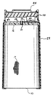
BRIEF DESCRIPTION OF THE DRAWINGS

For a fuller understanding of the nature and

objects of the invention, reference should be made to
the following detailed description taken in conjunction
with the accompanying drawings, in which:

Figure 1 is a partially cross sectioned side view
of a device in accordance with one embodiment of the
invention;

Figure 2 is a perspective view of a housing in
accordance with one embodiment of the invention;
Figure 3 is a perspective view of a device in
accordance with one embodiment of the invention;
Figure 4A shows a substrate with a fuse in
accordance with one embodiment of the invention;
Figure 4B is a cross sectional side view of the
substrate and fuse shown in figure 4A taken along the
line 4B -- 4B;


CA 02379009 2002-03-27

-2-
Figure 5A shows a substrate with a fuse in
accordance with one embodiment of the invention;
Figure 5B is a cross sectional side view of the

substrate and fuse shown in figure 5B taken along the
line 5B -- 5B; and

Figure 6 shows a substrate with several fuses in
accordance with one embodiment of the invention.
DETAILED DESCRIPTION

The present invention is a power providing device.
Figures 1, 2 and 3 show an embodiment of the invention
that includes a battery 10 having a terminal pin 13

extending from a header 16. The battery 10 may include
an electrode 19 having lithium. The battery 10 may be a
primary (non-rechargeable) battery, or may be a
secondary-battery (rechargeable).

A substrate 22 may be attached to the battery 10,
and a fuse 25 may be attached to the substrate 22 and
electrically connected to the terminal pin 13. Figures
4A and 4B show a substrate and a fuse. The fuse 25 may
include copper or tin, or both. The fuse 25 may be

designed to separate at less than about 20 amps of
electric current.

The protective housing 28 may be attached to the
battery 10, for example with shrink wrap 29. The
substrate 22 may contact the housing 28. The protective
housing 28 may have an orifice 31 within which the


CA 02379009 2002-03-27

-3-
terminal pin 13 may reside. A conductive terminal cap
34 may be attached to the housing 28. The substrate 22
may reside between the terminal cap 34 and the battery
10. The substrate 22 may reside between the terminal
cap 34 and the housing 28.

Figures 4A and 4B show a fuse having a
substantially straight conductive path. Figure 5 shows
a fuse 25 that provides a zig-zag conductive path. In
this manner, the size of the substrate 22 need not

change to accommodate fuses 25 of differing lengths.
Figures 4A and 4B show an embodiment of the
invention in which the fuse 25 is embedded in the
substrate 22. In this fashion, the fuse 25 may be
protected from damage that might otherwise be caused,
for example, during assembly of the substrate 22 with

the battery 10. The customary glass enclosure found in
many fuses may not be present.

Figure 6 shows an embodiment of the invention in
which several fuses 25a, 25b, 25c each having a
different current limit, may be placed on a single

substrate 22. For example, a single substrate 22 may
have fuses 25a, 25b, 25c of differing cross sectional
area, length or material so as to provide fuses 25a,
25b, 25c each having a different current limit. In
assembling such a substrate 22 with the battery 10, the
fuse (25a, 25b, or 25c) having the desired current limit
may be electrically connected to the battery 10 and, for
example, an electrical device 40. The other fuses may


CA 02379009 2011-09-01
-4-

not be electrically connected to provide a conductive
path from the battery 10, although they may be connected
to=the terminal pin 13 of the battery 10. In this
fashion, a single type of substrate 22 may be stocked
for use with many different types of batteries 10 or
electrical devices 40, or both.

The substrate 22 may include a ceramic material, a
polyamide material, polytetraflouroethylene, glass
reinforced hydrocarbon/ceramic laminate,-.or some
combination of the foregoing materials. Examples of
glass reinforced hydrocarbon/ceramic laminates include
those made. by Rogers Corporation of Chandler,: Arizona
and marketed-under the trademark R04000 Series.

A.compressible pad.37 may be included to firmly
hold the.substrate 22 within the housing 28. As shown.
in figure 1, the compressible pad 37 may contact an
electrical device 40 in order to hold the substrate 22.
However, it should be noted that the compressible pad 37
may also contact the substrate 22.

Although the invention has been described with
respect to one or more particular embodiments, it will
be understood that other embodiments of the invention

may be made without departing from the scope of the claims
appended hereto.

Representative Drawing
A single figure which represents the drawing illustrating the invention.
Administrative Status

For a clearer understanding of the status of the application/patent presented on this page, the site Disclaimer , as well as the definitions for Patent , Administrative Status , Maintenance Fee  and Payment History  should be consulted.

Administrative Status

Title Date
Forecasted Issue Date 2012-05-22
(22) Filed 2002-03-27
(41) Open to Public Inspection 2002-09-27
Examination Requested 2007-01-24
(45) Issued 2012-05-22
Expired 2022-03-28

Abandonment History

There is no abandonment history.

Payment History

Fee Type Anniversary Year Due Date Amount Paid Paid Date
Application Fee $300.00 2002-03-27
Registration of a document - section 124 $100.00 2002-06-26
Maintenance Fee - Application - New Act 2 2004-03-29 $100.00 2004-02-25
Maintenance Fee - Application - New Act 3 2005-03-28 $100.00 2005-01-05
Maintenance Fee - Application - New Act 4 2006-03-27 $100.00 2006-03-03
Request for Examination $800.00 2007-01-24
Maintenance Fee - Application - New Act 5 2007-03-27 $200.00 2007-03-08
Maintenance Fee - Application - New Act 6 2008-03-27 $200.00 2008-03-05
Maintenance Fee - Application - New Act 7 2009-03-27 $200.00 2009-03-04
Maintenance Fee - Application - New Act 8 2010-03-29 $200.00 2010-03-02
Maintenance Fee - Application - New Act 9 2011-03-28 $200.00 2011-03-03
Registration of a document - section 124 $100.00 2011-10-13
Maintenance Fee - Application - New Act 10 2012-03-27 $250.00 2012-03-02
Final Fee $300.00 2012-03-09
Maintenance Fee - Patent - New Act 11 2013-03-27 $250.00 2013-03-01
Maintenance Fee - Patent - New Act 12 2014-03-27 $250.00 2014-02-14
Maintenance Fee - Patent - New Act 13 2015-03-27 $250.00 2015-03-04
Maintenance Fee - Patent - New Act 14 2016-03-29 $250.00 2016-03-02
Maintenance Fee - Patent - New Act 15 2017-03-27 $450.00 2017-03-02
Maintenance Fee - Patent - New Act 16 2018-03-27 $450.00 2018-03-07
Maintenance Fee - Patent - New Act 17 2019-03-27 $450.00 2019-03-06
Maintenance Fee - Patent - New Act 18 2020-03-27 $450.00 2020-03-04
Maintenance Fee - Patent - New Act 19 2021-03-29 $459.00 2021-03-03
Owners on Record

Note: Records showing the ownership history in alphabetical order.

Current Owners on Record
ELECTROCHEM SOLUTIONS, INC.
Past Owners on Record
BRONNENBERG, DOUGLAS L.
GREATBATCH LTD.
RONALD, TIMOTHY R.
WILSON GREATBATCH LTD.
ZAYATZ, ROBERT D.
Past Owners that do not appear in the "Owners on Record" listing will appear in other documentation within the application.
Documents

To view selected files, please enter reCAPTCHA code :


To view images, click a link in the Document Description column. To download the documents, select one or more checkboxes in the first column and then click the "Download Selected in PDF format (Zip Archive)" or the "Download Selected as Single PDF" button.

List of published and non-published patent-specific documents on the CPD .

If you have any difficulty accessing content, you can call the Client Service Centre at 1-866-997-1936 or send them an e-mail at CIPO Client Service Centre.


Document
Description 
Date
(yyyy-mm-dd) 
Number of pages   Size of Image (KB) 
Cover Page 2002-09-06 1 29
Representative Drawing 2002-06-27 1 8
Abstract 2002-03-27 1 7
Description 2002-03-27 4 164
Claims 2002-03-27 3 75
Drawings 2002-03-27 5 82
Abstract 2011-09-01 1 13
Description 2011-09-01 4 146
Claims 2011-09-01 3 62
Description 2011-02-01 4 156
Claims 2011-02-01 3 67
Representative Drawing 2012-04-26 1 10
Cover Page 2012-04-26 1 37
Fees 2006-03-03 1 31
Correspondence 2006-05-08 1 16
Fees 2007-03-08 1 27
Correspondence 2002-05-02 1 23
Assignment 2002-03-27 2 96
Correspondence 2002-06-11 2 89
Assignment 2002-06-26 7 255
Correspondence 2002-06-26 2 55
Assignment 2002-03-27 3 153
Fees 2006-03-03 2 59
Fees 2004-02-25 1 33
Fees 2005-01-05 1 33
Correspondence 2006-03-10 1 19
Correspondence 2006-03-24 1 29
Correspondence 2006-06-06 2 2
Correspondence 2006-07-06 1 2
Fees 2006-06-15 7 195
Prosecution-Amendment 2007-01-24 1 35
Prosecution-Amendment 2007-03-19 2 34
Prosecution-Amendment 2011-07-22 2 65
Fees 2008-03-05 1 25
Fees 2009-03-04 1 42
Prosecution-Amendment 2010-08-04 2 65
Prosecution-Amendment 2011-09-01 9 234
Prosecution-Amendment 2011-02-01 7 200
Assignment 2011-10-13 14 477
Correspondence 2012-03-09 2 51