Note: Descriptions are shown in the official language in which they were submitted.
CA 02379401 2002-O1-15
WO 01/06291 PCT/DE00/02324
Description
Optical conductor connector, and a method for
connection to the end of an optical conductor
The invention relates to an optical conductor connector
having an optical conductor piece fixed in the factory
in a ferrule, the end of the optical conductor directed
outward being provided with a ground surface, and the
end directed inward projecting from the ferrule and
being connected by thermal welding to the inserted end
of an optical conductor to be connected, the ferrule
further being fixed in a ferrule holder.
Furthermore, the invention relates to a method for
connecting this optical conductor connector to the end
of an optical conductor.
Two groups of connectors, factory-fitted and field-
mounting connectors, are known per se. Very good
mechanical and optical properties can be achieved with
factory-fitted connectors. It is thereby possible to
assemble all types of fibers onto the corresponding
connectors. The end faces of the connectors can be
provided according to the requirements with all known
sections such as, for example, 0°PC, APC or UPC.
However, it is disadvantageous in this case that this
type of connector must be provided with a piece of
glass fiber (pigtail) whose length is mostly between
2.5 and 3 meters. The end of this glass fiber piece is
then spliced onto the cable to be connected. However,
this produces an additional connection, or splice
point, which brings with it an additional loss in the
transmission link. This connecting point must then
additionally be surrounded by an appropriate mechanical
guard.
In the case of "field-mounting connectors", it is
advantageous that the cable to be connected can be
CA 02379401 2002-O1-15
WO 01/06291 - 2 - PCT/DB00/02324
connected directly to the connector. This eliminates
the additional splice, and also the additional
mechanical guard. A plurality of systems of field-
mounting connectors are known. In the case of a bonded
connector, the optical conductor is bonded in an
appropriate receptacle and the end face is subsequently
ground and polished. However, with some types of
section this grinding and polishing operation is very
difficult, or even cannot be executed at all. In the
case of what are termed spliced connectors, a synthesis
of factory-fitted and field-mounting connectors is
undertaken. With these connectors, the difficult part
of bonding in the optical conductors, and the grinding
of the end face are already carried out in the factory,
and the connection, or splicing on of the optical
conductor to be connected is then executed on site
during the actual field assembly. In principle, this
type of connector corresponds to a factory-fitted
connector, but no additional outlay is required here to
protect the splice point, because the splice is located
directly in the connector. Such a type of connector is
known by the name of "FuseLite connector" . In the case
of such a "FuseLite connector", use is made of a
factory-fitted ferrule with a bonded optical conductor
that is ground at the end face and in the case of which
an optical conductor piece projects on the second end
face. The optical conductor to be connected is mounted
directly onto this optical conductor piece by thermal
splicing inside the connector housing. This means that
in this region the connector must have appropriate
cutouts through which the arc must be guided for
welding. This means that in this region the connector
must consist of a material of high quality that is
exceptionally heat resistant. This material is not
permitted to warp at the existing high temperatures,
since otherwise it is impossible to achieve the
required splice quality. A high quality ceramic, for
example zirconium, is used as material for this
purpose.
CA 02379401 2002-O1-15
WO 01/06291 - 3 - PCT/DE00/02324
German laid-open application DE 19517750 discloses an
optical conductor connector in the case of which the
end of an already permanently fixed piece of optical
conductor is connected by thermal welding in a
connecting sleeve to the end of an optical conductor to
be connected. Recessed into the connecting sleeve for
this purpose are lateral openings through which the
welding electrodes are led up to the splice point.
It is the object of the present invention to create a
field mounting optical conductor connector in the case
of which the above-named difficulties relating to
splicing are simplified, and in the case of which it is
also possible to make use in the splice region of
materials not of such high quality. The object set is
achieved with the aid of an optical conductor connector
of the type explained at the beginning, by virtue of
the fact that the ferrule with the fixed optical
conductor can be detached from the ferrule holder
before the thermal welding of the optical conductor
end, in that the ferrule is pressed into a receptacle
of the ferrule holder after the thermal welding, in
that a basic housing with an axially operating
compression spring is arranged over the ferrule holder,
in that a crimping ring for fixing the stress member of
the optical conductor is pressed on the basic housing,
in that an anti-kink guard is applied over the cladding
of the optical conductor to be connected, and over the
end of the basic housing, and in that an outer housing
with latching elements is drawn on as a cover.
Furthermore, the object arises with the invention of
developing a method for connecting the connector
according to the invention to the end of an optical
conductor. This object set is achieved with the aid of
the method according to the features of claim 5.
CA 02379401 2002-O1-15
T~10 01/06291 - 4 - PCT/DE00/02324
Owing to the design of the optical conductor connector
according to the invention, it is to be emphasized as a
particular advantage by comparison with the prior art
that splicing the optical conductor piece held in a
ferrule onto the end of the optical conductor to be
connected can be executed not inside a connector
housing, but separately outside thereof. In addition,
it is now possible also to make use of a normal optical
splicer for the thermal welding of the optical
conductor ends. This means that a specially modified
splicer that must be tuned to the geometry of the
connector housing need not be used, as previously
customary, for the splicing. Moreover, the welding
takes place outside the ferrule, and so the material of
the ferrule is no longer exposed to the high
temperatures during the thermal welding operation.
After the welding operation, the optical conductor
connector is then assembled, the ferrule firstly being
pressed into a receptacle in a ferrule holder and
thereby fixed exactly in position. Subsequently, the
further individual parts of the optical conductor
connector, which have previously already been pushed in
the appropriate sequence onto the optical conductor to
be connected, are positioned over the ferrule and the
ferrule holder. This completely eliminates the
expensive splicing by welding inside the optical
conductor connector, and/or a ferrule specially
modified therefor and a splicer also specifically
created therefor. The splicing is therefore a routine
mounting operation such as is otherwise also carried
out in the case of any thermal optical conductor
splicing between two optical conductor ends. The design
of the optical conductor connector described therefor
also simultaneously characterizes the method according
to the invention, in accordance with which the optical
conductor connector is assembled after the finished
thermal welding of the optical conductor ends. It is
particularly advantageous in the case of the method
that the splicing is performed before the assembly of
CA 02379401 2002-O1-15
WO 01/06291 - 5 - PCT/DE00/02324
the optical conductor connector, using the distances
and dimensions prescribed by the individual parts.
Consequently, all the positions of the individual parts
are already prescribed for the assembly at this first
operation.
The invention will now be explained in more detail with
the aid of four figures, in which:
figure 1 shows the finally mounted optical conductor
connector,
figure 2 shows the optical conductor connector
according to figure 1, in a longitudinal
section,
figure 3 shows the basic housing of the optical
conductor connector with inserted ferrule,
and
figure 4 illustrates the cycle of the method according
to the invention for producing the thermal
welding of the optical conductor ends, and
for mounting the optical conductor connector.
The optical conductor connector in accordance with the
invention is illustrated in the assembled state in
figure 1. It therefore shows the ferrule 2, which is
inserted into a basic housing 11, and in which the
optical conductor piece 2a required for splicing is
centrally arranged. The end faces 3 of the ferrule 2
and of the optical conductor piece 2a have already been
provided at the factory with a suitable section such
as, for example, with one of the types of section 0°PC,
APC, UPC, which are known per se, such that no
complicated and difficult work need any longer be
executed when actually mounting the connector. An outer
housing 1, which is provided with the corresponding
latching elements 20a for fixing the optical conductor
' CA 02379401 2002-O1-15
~O 01/06291 - 6 - PCT/DE00/02324
connector, is mounted over the basic housing 11. The
anti-kink guard 13 proj ects at the opposite end of the
optical conductor connector. Also indicated is a
section II-II, which is explained in figure 2.
Figure 2 shows the entire inner design of the optical
conductor connector according to the invention, the
optical conductor connector already being finished at
the splice point 15. It follows therefrom that the
ferrule 2 with the optical conductor piece 2a already
inserted at the factory, and with the end face 3,
likewise provided with the desired section in the
factory, is pressed after splicing has been performed
in a receptacle 18 of the ferrule holder 9 and thereby
fixed. Located inside a bore 9a in the ferrule holder 9
are the ends, connected to one another at the splice
point 15, of the optical conductor piece 2a and of the
optical conductor 6 to be connected, which is freed
from its coating 7 in the welding point region. The
stress members 8, for example Kevlar fibers, of the
optical conductor 14 are fixed at the end of the basic
housing 11 with the aid of a crimping ring 12. The
basic housing 11 is secured in its position with the
ferrule 9 by resilient latching elements 19. A pressure
spring 10, which ensures the required contact pressure
with the connector inserted, is drawn on a rear step of
the basic housing 11. Also illustrated is the anti-kink
guard 13, which prevents impermissible kinking of the
inserted optical conductor 14. It may also be seen that
the cladding 17 has been provided during mounting with
longitudinal slots 17a.
Illustrated in figure 3 is the basic housing 11 with a
latching element 20b which serves for latching into the
outer housing, which surrounds it later. Also
illustrated is the inserted ferrule 2 with the optical
conductor piece 2a and the ground end face 3.
CA 02379401 2002-O1-15
WO 01/06291 - 7 - PCT/DE00/02324
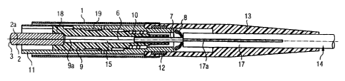
It follows from figure 4 how the individual parts of
the optical conductor connector are combined for
mounting before the splicing operation, and so the
method according to the invention can also be derived
from this illustration. Thus, the cladding 17 of the
optical conductor cable 14 is provided on a length of
approximately 20 mm with longitudinal slots 17a such
that the stress members 8 of the optical conductor 14
can be gripped. Moreover, the optical conductor 14 is
freed from its coating in the region of the welding
point 15 over a length of approximately 8 mm. The anti-
kink guard 13, the crimping ring 12 and the basic
housing 11 are now pushed in sequence over the cladding
17 of the optical conductor 14. The ferrule holder 9
with the pressure spring 10 mounted at the rear is
pushed on under the cladding 17 opened by longitudinal
slots 17a, the optical conductor still projecting with
its coating 7 over a length of approximately 10 mm. The
optical conductor 14 to be connected is thereby
prepared for splicing over a total length of
approximately 38mm with the end of the optical
conductor piece 2a projecting in the ferrule 2. The
end, prepared with the individual parts, of the optical
conductor 14 is now laid into a completely normal
thermal optical conductor splicer SG, known per se and
illustrated here only symbolically, and fixed in its
position with clamps E. From the other side of the
optical conductor splicer SG, the optical conductor
piece 2a already fixed in the ferrule 2 in the factory
is pushed in the opposite direction up to the splice
point 15 and likewise fixed with clamps E, the length
of the projecting optical conductor piece 2a being
approximately 6 mm. The dimensions in this figure are
to be regarded only as examples and are, of course, to
be adapted as appropriate in each case to the optical
conductor connector used. After the thermal splicing
has been carried out in the way known per se, the
ferrule holder 9 is pushed against the ferrule 2, the
latter being pressed into and fixed in a receptacle 18
CA 02379401 2002-O1-15
WO 01/06291 - 8 - PCT/DE00/02324
(see figure 2). The splice point 15, and also the
exposed optical conductor ends are thereby accommodated
in a protected fashion in the bore of the ferrule
holder 9. This design and mounting operation according
to the invention renders it possible to make use of a
commercially available optical conductor splicer.
Subsequently, the remaining individual parts previously
pushed on are then arranged over the ferrule holder 9,
the stress members 8 of the optical conductor 14
additionally being clamped and fixed on the ferrule
holder by the crimping ring 12. It is also expedient
for the ferrule holder 9 also to be pushed in further a
little by approximately 2 to 3 mm below the unslotted
cable cladding 17.
These measures according to the invention have rendered
it possible for the welding point certainly to be
situated inside the optical conductor connector when
the optical conductor to be connected is spliced on,
without the need to provide special bores or cutouts
for the welding operation in the ferrule. This
simplifies the ferrule very greatly, since, firstly,
there is no need to use high-temperature resistant
material and, secondly, a simple sleeve shape is
completely sufficient. It is advantageous, in addition,
that this method also requires no modification or
reconfiguration of optical conductor splicers.