Language selection

Search

Patent 2379466 Summary

Third-party information liability

Some of the information on this Web page has been provided by external sources. The Government of Canada is not responsible for the accuracy, reliability or currency of the information supplied by external sources. Users wishing to rely upon this information should consult directly with the source of the information. Content provided by external sources is not subject to official languages, privacy and accessibility requirements.

Claims and Abstract availability

Any discrepancies in the text and image of the Claims and Abstract are due to differing posting times. Text of the Claims and Abstract are posted:

  • At the time the application is open to public inspection;
  • At the time of issue of the patent (grant).
(12) Patent: (11) CA 2379466
(54) English Title: REAR CAB LATCH MECHANISM
(54) French Title: MECANISME DE VERROUILLAGE DE DOS DE CABINE
Status: Expired
Bibliographic Data
(51) International Patent Classification (IPC):
  • B62D 25/12 (2006.01)
  • B62D 33/06 (2006.01)
  • B62D 33/067 (2006.01)
  • B62D 33/07 (2006.01)
  • E05C 3/12 (2006.01)
(72) Inventors :
  • PEDDYCORD, JEFF (United States of America)
  • PHILIPPS, DAVID (United States of America)
(73) Owners :
  • VOLVO TRUCKS NORTH AMERICA, INC. (United States of America)
(71) Applicants :
  • VOLVO TRUCKS NORTH AMERICA, INC. (United States of America)
(74) Agent: GOWLING WLG (CANADA) LLP
(74) Associate agent:
(45) Issued: 2008-03-18
(22) Filed Date: 2002-03-27
(41) Open to Public Inspection: 2002-10-05
Examination requested: 2007-01-12
Availability of licence: N/A
(25) Language of filing: English

Patent Cooperation Treaty (PCT): No

(30) Application Priority Data:
Application No. Country/Territory Date
09/826,631 United States of America 2001-04-05

Abstracts

English Abstract

An over the highway vehicle having a forwardly pivotal cab mounted on a frame is disclosed. A latch assembly is interposed between the frame and the cab. The latch assembly includes coacting subassemblies including a catch for releasable retention by a latch. One of the subassemblies is connected to the frame and the other of the subassemblies is connected to the cab. The cab connected subassembly includes an impact absorbing yieldable element for normally maintaining a connected cab in a latched position. The element is extensible upon such vehicle experiencing a collision to allow controlled and limited forward tilting of the cab occasioned by the force of such a collision while maintaining the cab in a latched condition. A process of absorbing collision forces is also disclosed.


French Abstract

Un véhicule routier comportant une cabine pivotant vers l'avant sur un châssis est décrit. Un dispositif de verrouillage est interposé entre le châssis et la cabine. Le dispositif de verrouillage comprend des sous-ensembles coopérant, comprenant un loquet de retenue pouvant être libéré par le mécanisme de verrouillage. L'un des sous-ensembles est connecté au châssis et l'autre sous-ensemble est connecté à la cabine. Le sous-ensemble connecté à la cabine comprend un élément d'absorption d'impact déformable pour maintenir normalement une cabine connectée dans une position verrouillée. L'élément est extensible lorsque ledit véhicule entre en collision pour permettre à la cabine de basculer vers l'avant de manière contrôlée et limitée sous l'effet de la force d'une telle collision tout en maintenant la cabine dans un état verrouillé. Un processus d'absorption de forces de collision est également décrit.

Claims

Note: Claims are shown in the official language in which they were submitted.


6


In the Claims:


1. For use in an over the highway vehicle having a forwardly pivotal cab
mounted on a frame and having a latch assembly interposed between the
frame and the cab, the improved latch assembly comprising:
a) a latch subassembly including a latch;
b) a co-acting subassembly including a catch for releasable
retention of the latch;
c) one of the subassemblies being connectable to such frame and
the other of the subassemblies being connectable to such cab; and
d) a first of the subassemblies including an impact absorbing
yieldable element for normally maintaining a connected cab in a latched
position, the element being extensible upon such vehicle experiencing a
collision to allow controlled and limited forward tilting of such cab
occasioned
by the force of such a collision while maintaining such cab in a latched
condition.

2. The assembly of claim 1 wherein the latch subassembly is a hat
section connected to the cab and the co-acting subassembly is a latch
connected to the chassis.

3. The assembly of claim 1 wherein the first of the subassemblies is said
other subassembly.

4. The assembly of claim 1 wherein the latch subassembly is said one
subassembly.

5. In an over the highway vehicle of the tilt cab type, an improved latch
assembly comprising:
a) a pair of subassemblies including coacting latching elements for
releasably securing the subassemblies together,
b) one of the subassemblies being connected to a rearward


7


portion of the cab and the other of the subassemblies being connected to a
vehicle frame;
c) the subassemblies having an interconnected condition for
maintaining the cab in an operating position, the interconnected condition
being releasable to permit tilting of the cab to facilitate servicing of the
vehicle;
d) a first of the subassemblies including a force absorbing member
for minimized cab damage in the event of a vehicle collision, the member
including a U-shaped portion with arms respectively coupled to the frame and
cab when the subassemblies are in the interconnected condition; and,
e) the member having sufficient tensile strength to resist
separation when stressed and having sufficient flexibility to yield and absorb

collision induced forces.

6. The assembly of claim 5 wherein said one subassembly is said first of
the subassemblies.

7. The assembly of claim 6 wherein said first of the subassemblies also
includes a mounting bracket having a component which is sufficiently
frangible to fail under forces imparted by a vehicle collision.

8. The assembly of claim 5 wherein said first of the subassemblies also
includes a mounting bracket having a component which is sufficiently
frangible to fail under forces imparted by a vehicle collision.

9. The assembly of claim 8 wherein on collision impact, said component
will fail thereby absorbing initial energy of impact and the force absorbing
member will thereafter be straightened to absorb further forces while the
assembly maintains a connection of such cab to a vehicle frame.

10. A latch assembly for use in connecting a tilt cab to a vehicle frame
comprising:


8

a) ~a pair of subassemblies including a latch and a coacting catch;
b) ~the subassemblies each including mounting sections, one of the
mounting sections being for connection to such frame, the other of the
sections being for connection to such cab; and,
c) ~one of the subassemblies including a foreshortened force
absorbing element adapted to be effectively lengthened upon application of a
significant force tending to separate the subassemblies.


11. The assembly of claim 10 wherein the force absorbing element is an
elongate metal element having a bend reducing the effective length of the
elongate element, the bend being adapted to be straightened upon
application of such significant force.


12. The assembly of claim 11 wherein the one subassembly further
includes a frangible bracket.


13. The assembly of claim 10 wherein the one subassembly further
includes a frangible bracket.


14. The assembly of claim 10 wherein said other mounting section is a
portion of said one subassembly.


15. For use in a tilt cab vehicle a latch assembly comprising:
a) ~a pair of subassemblies including a coacting catch and latch
mechanism; and,
b) ~one of the subassemblies including:
i) ~a main mounting bracket including a mounting section
and an integrally formed U-shaped tongue extending from the section with a
part of the tongue in generally parallel relationship with the section;
ii) ~a goose necked channel carrying a selected one of the
latch and catch;
iii) ~a frangible mounting bracket secured to the channel at a


9

location spaced from said selected one;
iv) ~an end portion of the tongue remote from the section
being fixed to the channel at a location between said selected one and the
brackets; and,
v) ~the main and frangible brackets being juxtaposed with
the frangible bracket interposed between the main bracket and said part.

16. The assembly of claim 15 wherein the catch is a part of said one
subassembly.


17. The assembly of claim 16 wherein the other of the subassemblies
includes a post and the latch is carried by the post.


18. The assembly of claim 15 wherein the other of the subassemblies
includes a post and the latch is carried by the post.


19. The assembly of claim 18 wherein said one subassembly is adapted to
be mounted on a vehicle cab and said other subassembly is adapted to be
mounted on a vehicle frame.


20. The assembly of claim 15 wherein said one subassembly is adapted to
be mounted on a vehicle cab and said other subassembly is adapted to be
mounted on a vehicle frame.


21. A process of absorbing collision forces to minimize damage to a
vehicle tilt cab upon occurrence of a collision, the process comprising:
a) ~releasably coupling the cab to a vehicle chassis at a location
remote from a pivotal connection of the cab to the chassis;
b) ~allowing a supplemental bracket to be fractured by extension of
a U-shaped tongue of a main bracket due to impact forces; and
c) ~maintaining a connection between the cab and a latch
mechanism as and after the tongue is extended whereby impact forces are


absorbed and the coupling of the cab to the chassis is maintained.

Description

Note: Descriptions are shown in the official language in which they were submitted.


CA 02379466 2002-03-27

15-723
REAR CAB LATCH MECHANISM
Technical Field
This invention relates to a latching mechanism and more particularly to
a latch assembly especially suited for securing a vehicle tiltable cab in an
upright operating position.
Backaround of the Invention
Cab-over-engine vehicles have been manufactured in quantity for at
least half a century. An, advantage of such vehicles, is that the overall
length
of a vehicle is reduced as compared to a so-called pconventional"; cab behind
engine vehicle. For over the highway hauling, cab over engine vehicles are
advantageous where the vehicle is operated in jurisdictions where there are
legal limits on the overall length of a vehicle. Such vehicles are also
advantageous where maneuverability is important such as for intra-city
deliveries.
At least in heavy duty vehicles, cab over engine vehicles are of the tilt
cab type. That is, the cab is hingedly connected to a vehicle frame near the
front of the vehicle, while the back of the cab is releasably latched to the
frame.
Cab latches must be durable to withstand long vehicle life. They also
must positively maintain a connection between the cab and the frame during
vehicle operation. While such latches must maintain positive connections,
prior latches which are satisfactory for the purpose, have had inherent
drawbacks. If a latch mechanism fails to maintain a connection between the
back of a cab and the frame during a collision, severe damage to the cab and
a potential excessive injury to occupants can result. As a consequence, prior
latches have been designed to maintain cab to frame connections,even
during severe collisions. While such positive connections are clearly more
desirable than a latching mechanism which fai1s during a coflision, a rigidly
positioned cab will often experience excessive damage during a collision.
Accordingly, it would be desirable to provide a latching mechanism
which is durable, which will maintain a cab to frame connection upon a


CA 02379466 2002-03-27

2
collision,.but yet is energy absorbing to minimize structural damage to the
vehicle and injury to a vehicle occupant.

Summary of the Invention
A cab latching mechanism made in accordance with the present
invention, positively connects a cab to a frame in a reliable and durable
manner. At the same time, the mechanism- is designed to partially fail in a
controlled manner while maintaining a cab to frame connection in the event of
a collision. The partial failure absorbs impact energy minimizing damage to
i:o the vehicle. Tests have shown that while the unit partially fails and
absorbs
energy, it nonetheless meets and exceeds impact test requirements by
maintaining a connection between the cab and the vehicle.frame upon
impact.
In the disclosed and preferred erribodiment, a latch subassembly is
fixed to a vehicle frame. This subassembly is known as a striker bracket. A
coacting subassembly known as a hat section is connected to a cab. The hat
section includes a catch which is retained by the latch during normal
operation. The latch is of a conventional design which permits ready
decoupling when a vehicle cab is to be tilted forwardly such as a for access
to the vehicle engine for service.
The hat section includes main and frangible mounting brackets. The
main mounting bracket includes a U-shaped tongue which in the preferred
embodiment extends downwardly from a body of the main bracket that is
secured to the cab. The tongue includes a U-shaped part so that the tongue
includes an upstanding portion.
A channel is connected to and extends from the frangible bracket. An
upper end of the tongue upstanding part is fixed, as by welding, tothe
channel. The catch is atso fixed to the channel.
In the event of a collision of substantial force, the frangible bracket
fails allowing the tongue to extend and increase its effective length as
forces
are absorbed. This allows the cab to tilt forwardly.a relatively small amount
as compared to the forward tilting to, for example, gain.engine access. The


CA 02379466 2002-03-27

3
tongue after extension is still connected to both the channel and the body of
the main bracket so that the cab, while forwardly tilted a controlled amount,
nonetheless is securely fastened to the frame by the latching assembly.
Accordingly, the objects of this invention are to provide a novel and
improved energy absorbing latching system for a vehicle of the tilt cab type
and a process of absorbing energy in the event of vehicle collisions.

Brief Descriotion of Drawinfas
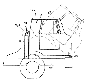
Figure 1 is an elevational view of a forward portion of an over the
highway vehicle of the tilt cab type showing the cab in its normal operating
position in solid lines with a forwardly tilted position being shown in
phantom;
Figure 2 is a front perspective view of the latch subassembly of the
present invention on an eniarged scale with respect to Figure 1;
Figure 3 is a rearward perspective view of the latch subassembly of
Figure 2;
Figure 4 is an enlarged view showing the catch subassembly and a
latch member in cross-section;
Figure 5 is a view corresponding to Figure 4 except that it is showing
the catch subassembly in its condition after it has absorbed an impact;
Figure 6 is a view corresponding to Figure 1 after the vehicle has
absorbed impact forces and the catch subassembly has been distorted to the
configuration of Figure 5; and,
Figure 7 is an enlarged perspective view showing the catch
subassembly after it has absorbed a collision force.

Detailed Descrintion of the Preferred Embodiment
Referring to the drawings, an over the highway vehicle of the tilt cab
type is shown generally at 10 in Figures 1 and 6. The depicted vehicle 10 is
either a truck or tractor depending on what is mounted on a frame 12 in that
portion of the vehicle not shown in the drawings. An operator cab 14 is
mounted on the frame 12. The cab 14 is pivotably connected to the frame
near a front of the vehicle at a location indicated by the reference numeral
15.


CA 02379466 2002-03-27

4
The pivotal mounting of the cab is conventional and well known to those
skilled in the art.
A latch post 16 is mounted on and fixed to the frame 12. A latch
assembly 18 is mounted on the post 16 and connected to the cab 14. More
specifically a latch subassembly 20 is fixed to the post 16 while a catch
subassembly 22 is fixed to the cab as by bolts 24, Figures 2 and 7. The latch
subassembly 20 is of a conventional well known constructionin which a latch
member 26 is moveable in response to operator applied forces selectively to
connect and disconnect the latch member 26 to and from the catch member
28.
1. The Catch Subassembly 22
Referring in particular to Figures 2-7, the catch subassembly 22
includes a main mounting bracket 30. The main mounting bracket includes a
U-shaped tongue 32. The tongue extends downwardly from a mounting
portion of the bracket around a U-shaped bend and upwardly in parallel with
the mounting portion.
A goose neck channel 34 is provided. An upper end portion 36 of the
tongue is disposed within and welded to the goose neck channel 34. The
goose neck channel has an integrally formed frangible bracket part 38. The
bracket part 38 and the main bracket 30 are complementally shaped and
fixed to a back section 40 of the cab 14 by the bolts 24.
A tongue limiter plate 42 is fixed to walls 44 of the goose neck channel
34. The tongue limiter plate functions to limit distortion of the tongue 32
and
the goose neck channel 34 under the effects of collision produced forces.

Operation
In operation, the cab 14 is positioned in its solid line position of Figure
1. The latch member 26 is manipulated to engage the catch member 28 as
shown in Figures 1 and 4-6 to secure the latch member subassemblies 20, 22
together. When the latch member subassemblies are secured together, the
cab 14 is locked in its upright and operational position.
In the event that the yehicle experiences a collision, the catch member


CA 02379466 2002-03-27

subassembly will move from a configuration depicted best in Figures 2-4 to
the condition depicted in Figures 5-7. When a collision is experienced, which
collision applies significant forces to the latch assembly, a main portion of
the
goose neck is broken away from the frangible bracket part 38 as depicted in
5 Figures 5 and 7. Once the goose neck main portion as separated from the
frangible bracket, the U-shaped tongue is stretched to the lineal condition
best shown in Figure 5.
The extent of the extension of the U-shaped tongue is limited by the
limiter plate 42 as also best seen in Figure 5. The limiter plate 42 also
Zo functions as a reinforcement between the goose neck walls 44. Thus, on
impact the vehicle cab 14 can move from its operating position shown in
Figure 1 to a partially forwardly tilted position as shown in Figure 6. While
partially forwardly tilted, the cab is still securely fixed to the frame both
at its
forward pivot at 15 and through the latch post 16.
Although the invention has been described in its preferred form with a
certain degree of particularity, it is understood that the present disclosure
of
the preferred=form has been made only by way of example and that numerous
changes in the details of construction, operation and the combination and
arrangement of parts may be resorted to without departing from the spirit and
scope of the invention as hereinafter claimed.

Representative Drawing
A single figure which represents the drawing illustrating the invention.
Administrative Status

For a clearer understanding of the status of the application/patent presented on this page, the site Disclaimer , as well as the definitions for Patent , Administrative Status , Maintenance Fee  and Payment History  should be consulted.

Administrative Status

Title Date
Forecasted Issue Date 2008-03-18
(22) Filed 2002-03-27
(41) Open to Public Inspection 2002-10-05
Examination Requested 2007-01-12
(45) Issued 2008-03-18
Expired 2022-03-28

Abandonment History

There is no abandonment history.

Payment History

Fee Type Anniversary Year Due Date Amount Paid Paid Date
Registration of a document - section 124 $100.00 2002-03-27
Application Fee $300.00 2002-03-27
Maintenance Fee - Application - New Act 2 2004-03-29 $100.00 2003-12-31
Maintenance Fee - Application - New Act 3 2005-03-28 $100.00 2005-02-28
Maintenance Fee - Application - New Act 4 2006-03-27 $100.00 2006-02-16
Request for Examination $800.00 2007-01-12
Maintenance Fee - Application - New Act 5 2007-03-27 $200.00 2007-02-16
Final Fee $300.00 2008-01-03
Maintenance Fee - Application - New Act 6 2008-03-27 $200.00 2008-02-13
Maintenance Fee - Patent - New Act 7 2009-03-27 $200.00 2009-02-12
Maintenance Fee - Patent - New Act 8 2010-03-29 $200.00 2010-02-18
Maintenance Fee - Patent - New Act 9 2011-03-28 $200.00 2011-02-17
Maintenance Fee - Patent - New Act 10 2012-03-27 $250.00 2012-02-08
Maintenance Fee - Patent - New Act 11 2013-03-27 $250.00 2013-02-13
Maintenance Fee - Patent - New Act 12 2014-03-27 $250.00 2014-02-14
Maintenance Fee - Patent - New Act 13 2015-03-27 $250.00 2015-03-09
Maintenance Fee - Patent - New Act 14 2016-03-29 $250.00 2016-03-07
Maintenance Fee - Patent - New Act 15 2017-03-27 $450.00 2017-03-22
Maintenance Fee - Patent - New Act 16 2018-03-27 $450.00 2018-03-16
Maintenance Fee - Patent - New Act 17 2019-03-27 $450.00 2019-03-20
Maintenance Fee - Patent - New Act 18 2020-03-27 $450.00 2020-04-01
Owners on Record

Note: Records showing the ownership history in alphabetical order.

Current Owners on Record
VOLVO TRUCKS NORTH AMERICA, INC.
Past Owners on Record
PEDDYCORD, JEFF
PHILIPPS, DAVID
Past Owners that do not appear in the "Owners on Record" listing will appear in other documentation within the application.
Documents

To view selected files, please enter reCAPTCHA code :


To view images, click a link in the Document Description column. To download the documents, select one or more checkboxes in the first column and then click the "Download Selected in PDF format (Zip Archive)" or the "Download Selected as Single PDF" button.

List of published and non-published patent-specific documents on the CPD .

If you have any difficulty accessing content, you can call the Client Service Centre at 1-866-997-1936 or send them an e-mail at CIPO Client Service Centre.


Document
Description 
Date
(yyyy-mm-dd) 
Number of pages   Size of Image (KB) 
Representative Drawing 2002-06-28 1 10
Cover Page 2002-09-20 1 41
Abstract 2002-03-27 1 27
Description 2002-03-27 5 286
Claims 2002-03-27 5 200
Drawings 2002-03-27 3 105
Representative Drawing 2008-02-18 1 11
Cover Page 2008-02-18 1 43
Fees 2003-12-31 1 30
Prosecution-Amendment 2007-03-27 1 34
Assignment 2002-03-27 3 211
Fees 2005-02-28 1 30
Prosecution-Amendment 2007-01-12 1 40
Correspondence 2008-01-03 2 50