Note: Descriptions are shown in the official language in which they were submitted.
20-09-2001 GB00029f
CA 02379646 2002-01-16
W0144EP
SELF-COOLING CAN
This invention relates to a self-cooling can. In
particular, it relates to a can suitable for containing
beverage which includes a refrigeration device within
and/or attached to the can so that cooling may be
initiated at any time and anywhere, remote from a
domestic/commercial refrigerator.
The principles of refrigeration are well-
established, using refrigerant in an evaporator to
extract heat from the refrigeration compartment (or
freezer compartment, as applicable) and then releasing
heat from the refrigerant by means of a compressor and
condenser or, alternatively, in an absorber.
There are a number of problems associated with
adapting known refrigerating units~for cooling a beverage
in a can. Since the can is to be self-cooling, the
refrigeration device needs to be contained in or surround
the can. A typical beverage can has, for example, a
capacity of 330 ml and tooling, filling and handling
equipment is adapted for this size of can. It is clear,
therefore, that any internal refrigeration device will
either necessitate an increase in can size, with
associated equipment changes, or a decrease in the volume
of beverage which the can holds.
A further problem is the time taken to cool the
volume of liquid to a desired drinking temperature. The
flow of liquid/vapour through a miniature refrigeration
device and the choice of refrigerant may be limiting
factors in this. Clearly a non-toxic refrigerant is at
least desirable and possibly essential for use with
beverage.
AMENDED SHEET
20-09-2001 CA 02379646 2002-01-16 GB00029,
2
Finally, initiation of the cooling process should
ideally be a simple procedure for the consumer to carry
out.
US-A-4,669,273 describes a self-cooling beverage
container which uses a coiled tube within the beverage
can which releases a pressurised refrigerant to an
evaporator for cooling the beverage. Not only does this
device severely limit the capacity of the can available
for the beverage but there is also a safety issue
involved in the use of a pressurised refrigerant within
the can.
Phase change cooling devices are described in US-
4759191, US-4901535,US-4949549, US-4993239 and US-
5197302, for example. Such devices typically have an
evaporator chamber and an evacuated absorber chamber.
Liquid such as water in the evaporator vaporises due to a
drop in pressure when a valve between the two chambers is
opened and therefore removes heat from the evaporator to
do so. Latent heat of vaporisation is then absorbed by
heat removing material in the absorber chamber.
US-5018368 uses a desiccant/heat sink device for
absorbing water vapour from the evaporator.
None of these phase change devices are suitable for
cooling a product within a can due to the loss of can
capacity available for the product itself. Furthermore,
the length of time taken to cool a can of beverage is
unacceptable for practical purposes.
According to the present invention, there is
provided a self cooling can comprising: a cylindrical can
body for beverage product; an evaporator within the can
AMENDED SHEET
CA 02379646 2006-04-05
28.589-47
3
body for removing heat from beverage product surrounding the
evaporator, the evaporator comprising an annular component
having an inner and outer wall with a gap between the walls,
the curled edge of the outer wall being clipped onto a ridge
on an inside chine wall of the base of the can body to form
a sealed unit which holds a high vacuum and is isolated from
beverage product; an absorber unit fixed to the outside of
the can body and including a first desiccant region and a
second region containing heat sink material, the desiccant
region of the absorber unit comprising an absorber element
having at least one pocket for the desiccant; and means for
providing a vapour path from the evaporator to the absorber
unit such that, in use, when the vapour path is opened,
vapour passes from the evaporator to the desiccant region of
the absorber unit, the vapour being absorbed by the
desiccant and heat from at least one of the vapour and the
reaction of the desiccant being removed by the heat sink
material, thereby cooling product around the evaporator.
In another aspect of the invention, there is
provided a self cooling can comprising: a cylindrical can
body for beverage product; an evaporator within the can body
for removing heat from beverage product surrounding the
evaporator, the evaporator comprising an annular component
having an inner and outer wall with a gap between the walls,
the curled edge of the outer wall being clipped onto a ridge
on an inside chine wall of the base of the can body to form
a sealed unit which holds a high vacuum and is isolated from
beverage product; an absorber unit fixed to the outside of
the can body and including a first desiccant region and a
second region containing heat sink material, the second
region of the absorber unit comprising an absorber element
having at least one pocket for heat sink material; and means
for providing a vapour path from the evaporator to the
CA 02379646 2006-04-05
28,589-47
3a
absorber unit such that, in use, when the vapour path is
opened, vapour passes from the evaporator to the desiccant
region of the absorber unit, the vapour being absorbed by
the desiccant and heat from at least one of the vapour and
the reaction of the desiccant being removed by the heat sink
material, thereby cooling product around the evaporator.
By using an absorber which is external to the can,
only the evaporator will reduce the can capacity available
for the product.
By separating the absorber from the evaporator,
any risk that heat removed by the absorber offsets or even
negates the cooling effect of the evaporator is avoided.
The use of an evaporator and external absorber unit means
that the product is entirely isolated from the cooling
system and from direct contact with cooling material.
20-09-2001 CA 02379646 2002-01-16 U'g00029~
4
The product, which is usually a beverage, is thus
cooled by means of vapour which passes from the
evaporator to the absorber when the evaporator and
absorber are connected such that a vapour path is formed
by the connection. Cooling is thus achieved by natural
convection due to the evaporator being at a lower
temperature than the product. Where the evaporator
includes water in the form of a water-based gel coating,
for example, then a vacuum or a low pressure within the
evaporator and absorber is required to ensure that
evaporation occurs at relatively low temperature and to
optimise the rate at which cooling occurs. Ideally, the
rate of cooling is 30 F in a maximum of 3 minutes for
300m1 of beverage.
Preferably, either the desiccant region or the
second region of the absorber unit comprises an absorber
element having one or more pockets for the desiccant or
heat sink material respectively.
In one embodiment, the absorber element is a metal
container comprising one or more annuli such that these
annuli form one or more desiccant pockets. One possible
method of manufacturing the absorber and/or evaporator
elements is by multiply redrawing metal. Preferably, the
metal container and annuli thereof are surrounded by heat
sink material.
In an alternative embodiment, the absorber element
comprises one or more pouches, each divided into one or
more pockets filled with heat sink material. Where a
single pouch is used, it may comprise a corrugated strip
of heat sealed foil or laminate of film and foil which
AMENDED SHEET
CA 02379646 2006-04-05
28589-47
may be coiled within the absorber unit in order to provide
maximum cooling surface. In this embodiment, voids between
the pockets may be filled with desiccant.
Usually, the absorber is connectable to the base of
5 the can body for example, by heat shrink, glue or mechanical
attachment. This connection preferably comprises a valve
connected to the evaporator and a rupturable seal on the
absorber unit such that the absorber unit plugs into the
valve housing. Alternative connectors/actuation methods are
described in European patent no. EP 1200781.
According to a further aspect of the present
invention, there is provided a method of cooling a beverage
product in a can body, the method comprising: beading the
upper end of a metal container and reverse redrawing said
beaded container to form an evaporator element having an
outer wall formed from the upper end of the metal container
and an inner wall formed from the lower end of the metal
container, said inner and outer walls being spaced by a gap;
inserting the evaporator element into the can body and fixing
the evaporator in the can body by clipping the curled edge of
the evaporator onto a ridge on the inside chine wall of the
base of the can body to form a sealed unit which holds a high
vacuum and is isolated from beverage product; fixing an
absorber unit to the outside of the can body; evaporating
liquid in the evaporator and providing a vapour path from the
evaporator to a desiccant region of the absorber unit;
absorbing moisture from the vapour by reaction between the
desiccant and the vapour; and removing heat from at least one
of the vapour and reaction of the desiccant, thereby cooling
beverage product surrounding the evaporator.
CA 02379646 2006-04-05
28589-47
6
Preferred embodiments of the invention will now be
described, with reference to the drawings, in which:
Figure 1 is a side section of a self-cooling can
assembly according to a first embodiment of the invention;
Figure 2 is a side section of an absorber for the
can of figure 1;
Figure 3 is a side section of the can of figure 1,
fitted with an evaporator element;
Figure 3a is detail of a connection between an
evaporator and a can;
Figure 4 is an activation device for the assembly
of figure 1;
Figure 5 is a partial side section of the assembly
of figure 1 showing the activation device of figure 4 when
assembled;
Figures 6a to 6d are different views of a second
embodiment of absorber;
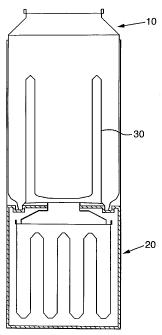
Figure 1 shows a first embodiment of self cooling
can comprising a can body 10, absorber unit 20 and
evaporator 30. The can body has a volume of around 380 ml so
as to contain 300 ml of product.
Figure 2 shows the absorber unit 20 which comprises
a multiple reverse redrawn container 22 which is formed in
typically seven stages from uncoated 0.16 mm tinplate.
Uncoated tinpiate avoids the possibility of outgassing
20-09-2001 CA 02379646 2002-01-16 GB00029i
7
from internal protection which might compromise internal
vacuum. Container 22 holds desiccant 24 and is, in turn,
placed within a plastic moulded container 25. Container
25 is filled with phase change acetate heat sink material
26.
Desiccant container 22 comprises concentric annuli
which form pockets for filling with approximately 70 to
130 ml of desiccant 24 so as to ensure a large area of
contact with surrounding heat sink material 26. Desiccant
container 22 may be vacuum seamed to a very high vacuum
level and closed by heat sealing a frangible foil
diaphragm 28, alternatively the vacuum may be pulled
during heat sealing. Heat sink acetate material 26 is
poured into the insulating container 25 from the base,
prior to closing by ultrasonic welding. The insulating
container is required to allow a consumer to handle the
absorber unit which would otherwise become hot during the
cooling of the beverage. Moulded features of insulating
container 25 include an attachment and engagement device
for activating the absorber unit when the valve assembly
(figure 4) penetrates foil.seal 28.
Evaporator element 30 (figure 3) comprises an
annular reverse redrawn component formed from steel or
aluminium. Usually the upper end of this element is
beaded prior to reverse drawing. The beading increases
the strength of the element and makes it possible to use
thinner materials. Beading also improves handling and
assembly of the component. The beaded evaporator is then
coated with lacquer or a polymer such as PET, and has a
finished height of 100 mm and diameter of 50 mm. A height
AMENDED SHEET
CA 02379646 2006-04-05
28589-47
8
of 100 mm.places the top of the evaporator approximately
mm below the surface of the liquid and is considered
to be the minimum necessary to give the optimum cooling
surface. The diameter is selected so as to pass through
5 the neck of a 202 diameter can (i.e. 2 2/16 inches
in diameter). The gap between the inner
and outer walls 32, 34 is kept to a minimum to avoid loss
of can volume available for product such as beverage. The
inner surface of the evaporator annulus is coated with a
film of water-based gel 35. An actuation valve (figure 4)
10 is fitted to an aperture pierced in the dome 14 of can
10. Alternative designs of actuation device are described
in European Patent no. EP 1200781.
As shown in the detail of figure 3a, the evaporator
element is sealed and clipped into the stand bead 12 of
can 10, under a formed ridge in the inside chine wall.
The edge of the evaporator element=30 is curled 36 and
beverage-approved water-based sealing compound 37 is
provided on the inside of the base of the can body
between the stand bead of the can and the curl to ensure
an hermetic seal. Curl 36 can either be snap fitted and
sealed over a ridge 38 which is formed by internal base
reform, or the evaporator may be secured in position by
post-reforming the ridge feature 38 around the evaporator
curl. This ensures that the evaporator maintains a high
vacuum (necessary to achieve the desired cooling rate for
the chilling process) and that the pressure of the
beverage will not compromise the seal.
Gel is applied to the evaporator internal surface by
flooding with a suspension of the powder in methanol,
pouring off the excess and then evaporating the remaining
20-09-2001 CA 02379646 2002-01-16 GB00029f
9
methanol. The dry film is then hydrated by flooding with
water and, again, pouring off the excess. A gel film of
approximately 0.5 mm is used to carry 10-12 ml of water
for cooling the 300 ml of beverage.
In use, the absorber unit 20 is pushed together with
the can/evaporator. A two piece valve assembly 40 such as
that of figures 4 and 5 may be used to displace any
trapped air and then seal in the aperture of the foil
closed desiccant chamber prior to breaking through the
foil 28 with valve apex 42. Valve 40 comprises a stem 45
of compressible material such as neoprene/nitrile and a
valve apex 42. Upper end of the stem 45 is covered with a
gas barrier layer 46. A ridge in the valve body ensures
that further penetration will result in compressing the
stem 45 of the valve just behind the plug 44, thereby
opening the vapour path. The insulating container 25 of
the absorber unit engages with the can dome resulting in
a positive snap fit of the absorber and evaporator units.
Figures 6a to 6d show a second embodiment of
absorber unit 50 for a self-cooling can. The absorber
unit 50 includes a continuous corrugated strip 52 of
aluminium foil. The corrugated layer 57 of strip 52 is
heat sealed between its corrugations to a second layer 58
to form a series of pockets 54. The ends of the strip are
also sealed, for example by heat sealing. As shown in
figure 6b, the corrugated side 57 is a thin film of
material, typically aluminium foil. Lower side 58, again
as depicted in figure 6b, may be foil.
Aluminium foil is the preferred material as this has
the necessary barrier properties which are required for
AMENDED SHEET
CA 02379646 2006-04-05
28.589-47
the high Vacuum levels involved. The foils used are
coated with heat-sealable lacquers on one side only, as
out-gassing from the lacquer will also compromise the
high vacuum.
5 The pockets 54 are filled with heat sink material
such as acetate and the strip is coiled (figure 6d) so as
to fit in an insulating jacket 56 within the heat
absorber container 20. Once coiled and in position in-
the absorber, desiccant is poured into the absorber to
10 fill voids between the pockets and around the coil 55.
In an alternative arrangment, instead of the single
coiled strip filled with acetate, individual pouches
containing heat sink material may be used. The pouches
are surrounded by desiccant as before.
Opening of a vapour path from the evaporator to.the
absorber unit enables vapour to contact desiccant
initially around the coil 55 (or individual pouches) and
thereafter to penetrate into the desiccant-filled voids
between the pockets of heat sink material. A typical
ratio of desiccant to heat sink material which is
required is 50:50 by volume.
The absorber unit of figures 6a to 6d may ideally be
used as an external absorber unit in conjunction with the
evaporator of figure 3 to replace the absorber unit of
figures 1, 2 and 5.