Note: Descriptions are shown in the official language in which they were submitted.
CA 02379787 2002-O1-29
WO 01/08799 PCT/EP00/07445
MICROFLUIDIC REACTION SUPPORT HAVING THREE FLOW LEVELS
AND A TRANSPARENT COVER LAYER
The present invention relates to a microfluidic
reaction support which, depending on the embodiment,
makes possible a purely fluidic or else light-
controlled synthesis and analysis of oligomers or
polymers. In addition, any other application as
miniaturized chemical or biochemical synthesis and
analysis platform, for example for application in
combinatorial chemistry, is in principle conceivable.
In general, the development of microfluidic systems is
still in its infancy. However, even now they represent
an important field, for example, in the area of
micropumps or microvalves. The focus of present studies
in this field is on the preparation of miniaturized
structures, preferably using semiconductor technology
methods.
Micrometering systems link microminiaturized pumps and
valves to sensors for drive and regulator circuits.
Such systems are currently developed and tested for
specific applications, for example for dosing of
medicaments or metering of very small amounts of
liquids in a free jet according to the inkjet printer
principle. These are used, for example, for preparing
"polymeric probe arrays" by spraying various
biochemical substances on defined positions of a
support body.
The mixing of media in microfluidic systems, for
example in chemical microreactors or in bioreactors but
also in chemical analysis systems, has not been
extensively studied to date. If very rapid mixing is
required, however, the use of specifically constructed
vortex zones or the use of a likewise miniaturized
mixer can achieve very high mixing rates. The
CA 02379787 2002-O1-29
- 2 -
development of micromixers is not market-ready yet and
is for the most part still in the experimental stage.
The interaction of fluid and wall, which is important
for the microfluidic reaction support of the invention,
has not to date been studied in detail.
Complete microfluid analysis systems have been realized
previously only in some cases, for example in systems
for analyzing the heavy metal content of ground water.
Test samples and functional samples of such microfluid
analysis systems are prepared by using preferably
various established silicon technologies such as, for
example, isotropic and anisotropic etching.
A great disadvantage of silicon technology is the
relatively high cost of material. For this reason,
various inexpensive technologies are currently
developed, which allow preparation of microstructures
as "throw-away articles". Three of these methods are
micro injection molding, miniaturized hot molding and
"LIGA" (light-induced galvanomolding) technology. These
methods allow in the experimental stage the preparation
of microstructures with dimensions of less than 1 ~,m.
These developments are presently applied, for example,
in DNA analysis. The current subject of research here
is a very rapid and therefore highly parallel
detection. The combination of hybridization as
detection principle and optical signal detection is in
the most advanced stage. In the USA, enormous resources
are being used to advance the development of these
miniaturized detection chips. The analytical
performance here is in the range from 104 to a maximum
of 105 bases per hour.
The aim is therefore to develop a technology with the
aid of which it is possible to analyze about and
greater than 105 bases per hour and to process the
obtained data such that meaningful interaction between
CA 02379787 2002-O1-29
r
- 3 -
user and the device to be used is possible. The core of
such a device is the subject of the present invention
and is described as microfluidic reaction support
below. This reaction support of the invention is
intended to form, for example, the central component of
systems for automatic fragment synthesis and fragment
analysis of oligomers or polymers. A system of this
kind is described in the patent application 19924327.1.
The reaction support of the invention includes a
structure of microchannels of different size, geometry
and function. Part of the microchannels serves to
supply and discharge fluid. All other channels serve as
reaction areas, and it is also possible, depending on
the application, to integrate optionally fluid
reservoirs, etc. into the microstructure. The flow
through the reaction support is either two-dimensional
or three-dimensional. The two-dimensional design
variant comprises at least in each case one feed and
one discharge channel in a single flow level. These two
channels are connected by a plurality of channels which
run approximately perpendicular thereto, and these
perpendicular connecting channels serve as preferred
reaction areas. The thus resulting reaction channels
can likewise be divided again into smaller channels,
each reaction channel comprising one or more reaction
areas. These reaction areas may be arranged, for
example, along the channel.
The more complex three-dimensional design variant
comprises three flow levels. The feed channels are
arranged in each case parallel to one another in a
first flow level and the discharge channels are
arranged in each case parallel to one another in the
third flow level, and feed and discharge channels are
arranged in a perpendicular projection either parallel
to one another or at an angle to one another, said
angle being chosen preferably as approximately 90°.
Moreover, perpendicular channels which form a third
CA 02379787 2002-O1-29
- 4 -
flow level and connect the feed channels of the first
level with the discharge channels of the third level
are arranged in the angled arrangement at the crossover
points of the channels in their perpendicular
projection or in the parallel arrangement along the
channels. Said connecting channels are substantially
narrower than the feed and discharge channels. This
makes it possible for fluid to flow over the reaction
areas in the feed and discharge channels without
entering the reaction channels. Several reaction
channels together form a reaction area.
Thus, the technical preconditions for a very rapid,
efficient and thus inexpensive provision of a
multiplicity of reaction areas have been created, for
example for the integrated synthesis of a multiplicity
of polymeric probes and the analysis of a multiplicity
of polymer fragments by means of said probes.
In all design variants, the fluids are discharged from
the reaction areas, without said fluids coming into
contact with another reaction area of the entire
reaction support. This is especially relevant in
reactions whose waste products could damage or destroy
other reaction areas.
All three variants of the microfluidic reaction support
of the invention have a cover layer on both the top and
the bottom. In the case of the two-dimensional
structure and also in the case of the parallel feed and
discharge channels of the three-dimensional structure,
at least one of the cover layers has a transparent
structure in order to make possible a light-controlled
photoactivation in the individual reaction areas by
individual illumination, for example by means of a
programmable light source matrix as described in the
patent application 199 07 080.6. All three variants are
constructed preferably with two cover layers, in order
to make possible a permanent optical process control in
CA 02379787 2002-O1-29
- 5 -
the reaction support and measurement of detection
reactions in transmitted light.
Various protective groups which are partly used also in
the synthesis of microarrays are known and available
for light-dependent photoactivation. Examples of
protective groups included here are MeNPOC, NPPOC and
its derivatives and also some older protective groups
which have been described by Pillai (Synthesis, 1980);
Hadrisan and Pillai (Proc. Indian nat. Sci. Acad. 53,
1987) or Birr et al (Liebigs Ann. chem. 763, 1972).
Moreover, methods in which photoactivation leads
indirectly via light-dependent activation of an acid
(photo acid) to a subsequent location-specific removal
of an acid-labile protective group such as, for
example, DMT are also known (see Gao et al in
WO 9941007). A similar mechanism can be utilized if
suitable photoresists are applied to the reaction
support (see McGall in PNAS 93, pp. 13555-13560, 1996).
In addition to these chemical methods it is also
conceivable to control synthesis by photoactivation and
photodeactivation of enzymes.
The more complex three-dimensional structure containing
the feed and discharge channels rotated at an angle
makes it possible to individually rinse each individual
reaction area of the vertically arranged microchannels.
This is carried out by rinsing in each case one feed
channel with fluid and discharging fluid through one
discharge channel. The fluid flows through the feed
channel into the perpendicular microreaction channels
and out of the reaction support again through the
discharge channel. In the same way it is possible to
rinse a plurality of reaction areas at the same time
and even with different fluids. Thus the microfluidic
reaction support of the invention, which has a
"cruciform structure" due to the angled arrangement,
CA 02379787 2002-O1-29
- 6 -
opens up a multiplicity of applications of
combinatorial chemistry or DNA analysis.
Another application is suffusing initially all feed and
discharge channels alternately with starting materials,
with the fluid supply and fluid discharge functions of
the feed and discharge channels alternating from cycle
to cycle. If, for example, each channel is rinsed with
a different building block of a polymeric probe to be
synthesized, then it is possible to generate over a few
cycles a large variety of oligomeric or polymeric
probes in the individual reaction areas of a reaction
support, due to the use of the cruciform structure.
Additionally, the synthesis of individual probes of any
specificity in a single reaction area is possible
without problems by individually driving a reaction
area as described above. Thus the inventive
microfluidic reaction support with cruciform structure
provides the possibility of efficient wet-chemical
"probe array" synthesis of oligomeric or polymeric
probes. This procedure is denoted "fluidic
multiplexing" hereinbelow. This also makes possible in-
situ synthesis by means of process monitoring and also
integrated synthesis and analysis.
The purely fluidic reaction control requires no
transparent cover layers which are, however, likewise
sensible for optical process control and for recording
detection reactions. In this case, detection may be
carried out likewise either in transmitted light or
else in back light from one side. If the three-
dimensional cruciform structure with its feed and
discharge channels arranged by rotation at an angle is
combined with the light-controlled photoactivation of
the reaction areas of microchannels, the efficiency of
synthesizing oligomeric or polymeric probes can be
increased still further. It is possible to integrate
both the light source matrix as light source and the
required detector into the microfluidic reaction
CA 02379787 2002-O1-29
_ 7 _
support. The same can be said for integrating a CCD
matrix as second opposite cover layer. It is also
possible to connect a programmable light source matrix
as cover layer directly. This suggests itself, in
particular if the microfluidic reaction support is
integrated into a device as a fixed component and is
purified, for example chemically, between uses and has
only to be changed for maintenance purposes. If the
microfluidic reaction support is exchanged after each
use, then, however, direct integration is not sensible.
In this case, it is recommended rather to arrange the
components in the system accordingly.
The invention likewise relates to supplying the
microfluidic reaction support with the appropriate
fluids. For this purpose a likewise novel integrated
valve system was designed. This allows rapid provision
of a multiplicity of fluids in the feed and discharge
channels of the microstructure.
This fluid supply system has been designed for applying
the microfluidic reaction support of the invention to
the synthesis of arrays of oligomeric or polymeric
probes in the reaction areas. The supply.system is
similar in the connections and components for the
"upper" and "lower" feed and discharge channels. All
channels are individually supplied from one side via a
multiplex valve described below. All channels are
combined at the in each case corresponding other end of
the channel, and this combining is used for feed and
discharge with uniform rinsing of all reaction areas.
V~lhen synthesizing oligomeric or polymeric probes in the
reaction areas, this refers to all cycles except for
feeding the specific individual building blocks
consisting of, for example, one or more nucleotides in
the case of DNA synthesis. If it is intended to reach
all reaction areas and not to select them specifically,
then it is better to choose a flow-optimized feed such
as, for example, dual ramification, rather than via the
CA 02379787 2002-O1-29
multiplex valve, which has a higher risk of delay.
However, the valve is required for feeding the specific
building blocks. Said valve connects the microchannels
of the reaction support on one side with an at most
identical number of individual tanks and a group
connection on the other side. In one valve position, in
each case one tank is connected with one or more
channels of the reaction support. If the fluid of a
single tank is intended to enter more than one channel
or channel bundle of the reaction support in a single
cycle, first one channel and then further channels are
provided in series. The group connection corresponds to
the combination of the channels on the in each case
opposite side of the reaction support. It serves to
efficiently rinse valve and reaction support.
The connections of the microfluidic reaction support to
its fluid supply and fluid disposal are an important
element. If the reaction support is purified time and
again and reused in the specific application, a
complicated connection technique, for example to the
multiplex valve, may be provided for. In this case, in
particular in the case of a large number of channels, a
design with a multiplicity of very small channels in
"legs", in analogy to semiconductor processor
technology, is possible. The disadvantage of this
design with respect to flow is the risk of deposits in
the bends and kinks of the individual microchannels.
Here, subsequent rinsing may be provided for, as for
avoiding delays. For the application variant in which
the reaction support is exchanged after each
application, rapid connections which seal without
adhesive are required. In this connection, it is
possible, for example, to connect flat to the front of
the reaction support, with a through bend-free channel
course. Thus the risk of delay is minimal. A second
alternative is pressing the bottom of the reaction
support onto the fluid feed. In this connection,
suitable seals resistant to chemicals have to be
CA 02379787 2002-O1-29
_ g _
provided for in each case.
In one aspect of the invention, purification means in
particular a complete regeneration of the reaction
support. Said support can then be used again in the
regenerated state for a new polymer synthesis. In the
case of chemical purification, it must preferably be
taken care that the linkage site required for attaching
a first polymer building block is not destroyed. The
predetermined breaking point necessary for chemical
purification may be cleaved by chemical (e. g. wet-
chemical, photo-chemical, electrochemical) or
biological (e.g. enzymic) transformation. Preference is
given to providing the predetermined breaking point
during the first surface derivatization of the
microfluidic reaction support, preferably in the linker
system which connects the surface to the first polymer
building block. In each case it is guaranteed that the
predetermined breaking point cannot be broken by the
analyte or reagents used during synthesis or during
analysis.
One-stage process:
The predetermined breaking point is broken by a single
transformation. Examples of this are base-labile
linkers, acid-labile linkers, oxidation-labile linkers
or degradation with the aid of suitable enzymes.
Apart from chemical purification, it is thus also
possible to carry out an enzymic purification of the
reaction support. In this case, the polymeric or
oligomeric probes linked to the reaction support are
cleaved or "digested" with a DNA- or RNA-degrading
enzyme or a peptide-cleaving enzyme, resulting in
degradation of a part or all of the probes. Afterward,
the reaction support can be used again for synthesizing
new probes.
Suitable enzymes are nucleases such as exonucleases or
CA 02379787 2002-O1-29
- 10 -
endonucleases which attack one nucleic acid strand from
the ends or within the probe strand and which leave
behind nucleotides or nucleosides as cleavage products.
In the case of RNA, it is possible to use RNAses (RNAse
H, etc.) which, if an RNA-DNA double strand has been
generated, selectively cut the RNA part resulting in
cleavage of the entire probe in the case of RNA probes
and of the RNA section in the case of RNA part sections
as predetermined breaking point. Likewise, a reaction
support can be regenerated with DNA probes by using
DNAses (DNAse I, DNAse II, etc.), and, as a result,
both single-stranded and double-stranded DNA can be
degraded.
Likewise, it is possible to use peptide-cleaving
enzymes for degradation of peptide probes or peptide
sequence sections as predetermined breaking point.
Multistage process:
The predetermined breaking point is broken in a
multistage process, i.e. the predetermined breaking
point is masked in some form. This requires firstly
removing said masking in one or more steps before in
the subsequent step the predetermined breaking point
can then finally be broken.
As an example a masked photolabile linker can be used,
in which an o-nitro function required for photolability
is only generated by a preceding transformation. This
may take place, for example, by oxidation of an amino
function. This, not necessarily specific, oxidation
step may be carried out enzymatically or wet-
chemically. Once the o-nitro function has been
generated, it is then possible for the predetermined
breaking point to be cleaved by irradiation with light.
Another possible solution is to generate in a first
step a double-stranded DNA sequence by adding an
analyte complementary to the linker, which is then in
CA 02379787 2002-O1-29
- 11 -
the next step recognized by a specific enzyme
(restriction enzyme) and is removed by specific
cleavage.
lnThen using an RNA part section as probe "base", it is
possible to chemically regenerate the reaction support
likewise in several stages. In this connection, the
synthesis is initially carried out using 2'-OH-
protected phosphitamide building blocks. After
hybridization and analysis, the protective group is
regenerated by cleaving off the RNA part section,
resulting in a free 2'-OH group. This may be followed
in a subsequent chemical reaction step by cleavage of
the ribose sugar with the aid of periodate or other
oxidants and removal of the probe from the reaction
support by ~ elimination.
The above-described purification (receptor removal)
processes have independent significance within the
scope of the invention, irrespective of a specific
embodiment of the support. The applicant reserves
putting forward, where appropriate, independent patent
claims regarding the described technology of
purification or receptor removal.
It should be pointed out that it is also possible to
remove the receptor or molecule by cleavage in the
sense explained above, in order to collect molecules
removed by cleavage and to use said molecules for
further chemical processes, for example for a synthesis
step. In this sense, the purification processes may be
seen as steps for obtaining molecules synthesized on a
support.
The microfluidic reaction support of the invention is
constructed in several layers, as is common also in
semiconductor microtechnology. In this case it is
possible to distinguish between dividing the
microstructure into functional layers and into layers
CA 02379787 2002-O1-29
- 12 -
due to the construction.
Tr~hile a two-dimensional structure has at least three
functional layers, a three-dimensional structure
consists of at least five functional layers. These
functional layers are described in more detail below.
During production is it often possible to integrate a
plurality of these functional layers by means of
suitable production methods into a layer due to the
construction.
The functional layers of the two-dimensional structure
contain a central structural layer into which the
microflow structure of channels, reaction areas and
reservoirs is introduced. It is connected with an upper
and a lower cover layer and may be made of glass,
plastic or silicon. Depending on the design, the
material used may be transparent or else lightproof. An
example of lightproof material, which is recommended,
is Futoran glass from Schott, silicon or Teflon.
The three-dimensional structures consist of five
functional layers, a first, "upper" cover layer, a
structure of microchannels, located underneath said
cover layer, for feeding and discharging fluid in a
manner analogous to the two-dimensional structure, a
central level of perpendicular, smaller (preferably by
at least a factor of 10) microchannels which serve as
reaction areas. At the "bottom" a level for fluid
supply and a cover layer follow, both of which are
designed similarly to the "top". Overall, the reaction
support is a construction mirrored at a central plane .
The preparation need not necessarily follow the
functional layers. Thus it is possible to integrate the
feed and discharge structure both into the central
layer and into the cover layer. It is possible to use
for the central layer with the perpendicular
microchannels as reaction areas, for example, suitable
silicon wafers from the semiconductor technology, which
CA 02379787 2002-O1-29
- 13 -
has etched "pores", from Siemens or fused glass fibers
(glass fiber wafers) from Schott, having etched-out
cores and a size ratio between wall thickness and
channel diameter of preferably 1 to 5. In order to
improve precise rinsing of only the "driven" reaction
channels, it is possible to supplement the central
functional level with an upper and a lower intermediate
layer. Said layer prevents or makes more difficult
unwanted streaming-in of fluids (hydrophilic or
hydrophobic barriers)
The preparation methods required can be distinguished
according to the material used. In the case of silicon
wafers, glass wafers and glass fiber wafers (with and
without core), the connection techniques used are
bonding methods. The parts such as, for example, the
various wafers are prepared by etching techniques and
also sawing and polishing. lr~hen plastics such as Teflon
which is lightproof and COC or polystyrene which is
transparent are used, methods such as injection
molding, hot molding or LIGA are used. The components
are connected, for example, by means of adhesive
bonding or ultrasound welding or by mechanical pressure
sealing by means of a holder or a frame.
The upper cover layer seals on the outside the
microflow structure lying underneath. This produces the
microchannels. The layer is transparent for introducing
light into said channels. In order to optimize the
optics, it is also possible to use microlenses made of
glass from Mikroglas or plastic (IMM Mainz). Likewise
possible is the use of a honeycomb structure made of
fused glass fibers which was developed, for example, by
Schott or ITT and is used, for example, in night vision
equipment. To this end, long glass fiber bundles are
heated such that they fuze and [illegible]. These may
then be bonded to glass or silicon or bonded or welded
to plastics.
CA 02379787 2002-O1-29
- 14 -
The proper use of the microfluidic reaction support of
the invention is as follows: firstly a group of
reaction areas is addressed via the microchannels of a
two- or three-dimensional microstructure. After the
reaction has taken place there, the reaction products
forming in the individual reaction areas are discharged
through microchannels, without the reaction product
flowing through another reaction area. In this
connection, driving of the reaction areas in the
described three-dimensional cruciform structure may be
utilized for purely fluidic synthesis of oligomers or
polymers from monomers, oligomers or polymers or else
for accelerating the light-controlled synthesis or a
combined wet-chemical and light-controlled synthesis of
oligomers or polymers by the described intelligent
multiplexing of the starting materials.
In the meantime, all reaction areas and microchannels
are optically controlled through transparent cover
layers, this being a platform for an in-situ synthesis,
a permanent process control and regulation of the
processes in the microstructure. This creates the basis
for a comprehensive quality assurance. Light signals of
detection reactions, which are produced in the reaction
areas by chemical (e. g. luminescence), biochemical
(e. g. bioluminescence) ar light-induced (e. g.
fluorescence) reactions, can be recorded in an
integrated apparatus for synthesis and analysis, which
encloses the fluidic microprocessor and is described in
the patent application 19924327.1. Furthermore,
absorption can be measured in the reaction support by
recording light signals which pass through the
microchannels and reaction areas in a transmitted-light
process or are reflected in a backlight process. This
may be utilized, for example, for an extended
qualitative quality assurance.
This microfluidic reaction support of the invention has
many different advantages: first, the reaction products
CA 02379787 2002-O1-29
- 15 -
are discharged from each reaction area without another
reaction area coming into contact with the reaction
products. This makes it possible to carry out reactions
for synthesis and analysis in those reaction areas
which generate reaction products (final products or
intermediates) which would be harmful to other reaction
areas.
Compared with planar surfaces, the three-dimensional
microchannels have a larger surface area which can be
utilized as a solid phase.
The use of microstructures reduces the amount of fluid
required for the reactions and at the same time
increases the reaction rate. This is the case both for
covalent bonds and, for example, for the hybridization
times for applications in DNA, RNA, PNA, LNA analysis
or for protein applications.
Transparent cover layers make possible photoreactions,
for example for the light-controlled synthesis of DNA,
RNA, PNA, LNA or proteins, etc.
Moreover, the transparent cover layers make possible a
permanent process control for regulating the reactions
and also the fluidics in the reaction support. This
leads to a distinct reduction in the mistakes both in
production and in detection, thus increasing the number
of analyzable measurements per use of material and
time.
A suitable layout of the geometry of the individual
reaction areas and the microchannels between the
reaction areas makes it possible to specifically
influence the beam paths, taking into account the
refraction indices present in the reaction support.
The fluidic microprocessors of the invention may be
designed as simple components for single use. In
CA 02379787 2002-O1-29
- 16 -
principle inexpensive plastic structures are to be
preferred here but possible designs are also glass and
silicon [lacuna] or else combinations of materials.
Rapid and inexpensive production makes possible a large
variety of individual applications in which probe
arrays can be synthesized and analyzed specifically,
for example by taking into account sequence and gene
databases on the Internet.
The reactions always take place on the walls of the
microreaction channels. Consequently, the reaction
areas always have a three-dimensional structure and
have a considerably larger surface area than the planar
base area. This three-dimensional geometry thus greatly
enlarges the utilizable reaction surface area. Said
size of the surface area is very important for the use
as solid phase. Said size may be important, for
example, for accumulation of oligonucleotides during
synthesis in the reaction support as well as for
accumulation of sample fragments flowing past during an
analysis in the reaction support.
The three-dimensional cruciform structure makes
applications, for example, in oligonucleotide analysis
or in combinatorial chemistry, etc. possible. Using the
two intersecting structures makes it possible to
generate quickly a multiplicity of different
combinations of oligomers or polymers in the individual
reaction areas of the reaction support. This makes
possible a very efficient wet-chemical synthesis of an
oligomeric or polymeric probe array in a reaction
support. This may be controlled by a computer, making
it possible to generate any nucleotide combinations in
each reaction area. The analysis may likewise be
carried out directly in the reaction support, making
permanent process control possible.
An appropriate multiplexing of the fluids can reduce
the number of preparation cycles of "probe arrays". The
CA 02379787 2002-O1-29
- 17 -
location-specific generation of a multiplicity of
different oligomeric or polymeric probes of, for
example, 20 bases in length on a planar surface by
means of local photoactivation requires on each level
four synthesis cycles, due to the four different bases.
Thus a total number of 4 x 20 - 80 cycles is required.
There is no systematic possibility of reducing the
number of synthesis cycles. On the other hand,
synthesis in the microfluidic reaction support offers
the possibility of distributing the starting materials,
i.e. monomers or oligomers, simultaneously on
microfluidic subareas. As a result, it is possible to
reduce the synthesis cycles, for example when using
tetramers, to a minimum of 5 cycles. The exact number
of cycles required for a specific probe array is
specific for each probe pattern and can be stated only
as statistical average, if the number of reaction areas
in the reaction support, the number of parallel fluidic
subspaces and the length of the oligomers to be
synthesized are given.
The following methods become applicable during the
reaction support of the invention: apart from the
synthesis of oligomers and polymers up to whole genes
and genomes, there is the possibility of "de novo"
sequencing of unknown polymers such as DNA, RNA, PNA,
LNA, proteins and others via sequence comparison with
processed sample material. In addition, it is possible
to "re"-sequence polymers, i.e. to compare known with
unknown sequences, the known sequences being
specifically selected. Likewise, it is possible to
prepare substance libraries for screening methods and
analytical methods, in particular for nucleic acid
analysis via hybridization.
All processes from synthesis to analysis of simple or
complex molecules can be integrated in the microfluidic
reaction support of the invention and can be carried
out very efficiently. This makes possible, for example,
CA 02379787 2002-O1-29
- 18 -
the flexible and cost-saving analysis of a large number
of polymers by providing a multiplicity of individual
and specific polymeric probes in a miniaturized format
and subsequent comparison of the probes with analytes
of the sample material. This makes it possible to
generate in screening methods and analytical methods a
large number of measurement data and thus to deal with
the wealth of information of biological systems
efficiently and in its entirety in a very short time.
Fields of application are also methods and devices for
the continuous, discrete fragment analysis, which are
accelerated by the present invention and therefore made
efficiently usable, and, in principle, all applications
of oligomer/polymer analysis, as in liquid
chromatography/high pressure liquid chromatography, gas
chromatography, thin layer chromatography, gel
electrophoresis, capillary electrophoresis, mass
spectrometry, etc. and also all "probe array"
applications. Furthermore supported is thus substance
development and testing of appropriate substances,
inter alia in pharmaceutical research. Further
important fields of application are molecular
diagnostics, DNA and/or RNA analysis, screening for
molecular interactions, for example in immunology,
molecular biology, histology and combinatorial
chemistry.
There is a multiplicity of design variants in the
design as well as in the production of the reaction
supports, which are depicted in the following drawings:
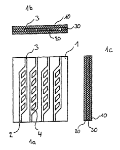
Fig. 1a shows a two-dimensional structure of the
microfluidic reaction support in plan view.
Fig. 1b and 1c show the corresponding sectional
illustrations: the microchannel structure 1 is
located in the central flow level 30 of the
reaction support. Said central flow level is
sealed by the lower cover layer 10 and the
CA 02379787 2002-O1-29
- 19 -
upper cover layer 20. The flow structure
consists of feed channels 2 and discharge
channels 3 and also of the reaction channels 4
located in between and having in each case at
least one reaction area.
Fig. 2 shows a three-dimensional structure of the
microfluidic reaction support in plan view.
Fig. 2b, 2c and 2d show the corresponding
sectional illustrations: the microchannel
structure 100 consists of the lower fluid feed
structure 32 with microchannels 102 and the
upper discharge channel structure 31 with the
microchannels 103. In the central layer 40 in
between are the connecting or reaction channels
in the reaction areas 104, which are arranged
nearly perpendicular to the feed and discharge.
The cover layers 20 and 30 are optionally
transparent or lightproof.
Fig. 3a, 3b and 3c show again the illustrations of Fig.
2a, 2b and 2c. In this case, the sectional
illustrations illustrate the course of the flow
through the feed channels 102, the reaction
channels 101 in the reaction areas 104 and
through the fluid discharge 103.
Fig. 4a shows a three-dimensional cruciform structure
of the microfluidic reaction support in plan
view. Fig. 4b, 4c, 4d and 4e show the
corresponding sectional illustrations: the
microchannel structure 200 is located in the
lower fluid feed and fluid discharge structure
32 with microchannels 202 and the upper fluid
feed and fluid discharge structure 31 with the
microchannels 203, in each case rotated by 90~
toward one another. In the central layer 40 in
between are located the connecting or reaction
channels in the reaction areas 204, which are
CA 02379787 2002-O1-29
- 20 -
arranged perpendicular to the feed and
discharge. The cover layers 20 and 30 are
optionally transparent or lightproof.
Fig. 5a, 5b and 5c show once more the illustrations of
Fig. 4a, 4b and 4c. In this connection, the
sectional illustrations of the microstructure
200 illustrate the course of flow through the
feed and discharge channels 202 and 203 and
also through the reaction channels 201 in the
reaction areas 204.
Fig. 6 shows the illustration of a single two-
dimensional flow structure in analogy to Fig. 1
with altered cross sections of the feed
channels 2 and the discharge channels 3 to
specifically influence the flow. The cross
section of the reaction channels 4 having in
each case at least one reaction area is
unaltered but may also be modified.
Fig. 7a shows in analogy to Fig. 6 a single two-
dimensional flow structure in which the cross
sections of the feed channels 2 and the
discharge channels 3 have been altered at the
level of the channels to specifically influence
the flow. Here, the cross section of the
reaction channels 4 having in each case at
least one reaction area has likewise been
altered and their size is not uniform. The
structure is closed by the cover layers 10 and
20 which are arranged at an angle.
Fig. 8 shows the illustration of a three-dimensional
flow structure in analogy to Fig. 2 and 3 with
altered cross sections of the feed channels 102
and the discharge channels 103 to specifically
influence the flow. The size of the reaction
channels in the reaction areas 104 is unchanged
CA 02379787 2002-O1-29
- 21 -
here.
Fig. 9 shows an illustration analogous to Fig. 8, with
the size of the reaction areas 104 differing
from the size of the feed channels 102 and
discharge channels 103.
Fig. 10a, lOb and lOc show an illustration analogous to
Fig. 3a, 3b and 3c, with the feed channels 102
and the discharge channels 103 altering their
height and thus influencing the flow. Due to
the thickness of the central structural layer
40, the reaction areas 104 and the reaction
channels 101 have a uniform length.
Fig. 11a, 11b, 11c, 11d and 11e show a three-
dimensional cruciform structure of the flow in
an illustration analogous to Fig. 4a, 4b, 4c,
4d and 4e and 5a, 5b and 5c, with altered cross
sections of the feed channels 202 and discharge
channels 203 to specifically influence the
flow. The size of the reaction channels in the
reaction areas 204 is unchanged here.
Fig. 12a shows the illustration of Fig. 5c of the
cruciform structure with two detail variants
12b and 12c. The detail 12b illustrates the
structure composed of the cover layers 10 and
20 and a central layer 40 having the reaction
areas in the reaction channels 201 and the feed
channels 202 and the discharge channels 203. In
detail 12c the reaction channels 201 of the
variant 12b are replaced in each case by a
three-layer microstructure. Said microstructure
comprises two layers 301 and 303 for smoothing
and stabilizing the feed flow and discharge
flow 202 and 203 and also an actual reaction
layer 302 made of further microchannels and,
for example, a glass fleece.
CA 02379787 2002-O1-29
- 22 -
Fig. 13 shows a connection variant of the
microcruciform structure 200 according to Fig.
4a, 4b, 4c, 4d, 4e and 5a, 5b and 5c with two
microflow channel variants 401 and 402. Both
variants connect a channel for the fluid supply
400 in each case with all parallel channels 202
and 203 of the two levels. Thus it is possible
to rinse all reaction areas 204 with fluid on
various feed and discharge variants at the same
time.
Fig. 14 shows an illustration analogous to Fig. 13 with
two valves 500 integrated into the fluid
supply. Said valves supply the microchannel
structure 200 via the channels in the first
level 202 and the second level 203. This makes
it possible to rinse the reaction channels in
the reaction areas 204 with fluid. It is
possible to rinse one, more or all reaction
areas 204 with fluid at the same time. The
valve position and the direction of flow
through the reaction channels make it possible
to rapidly realize any fluid supply cycles. All
that is required here is to change the position
of the valves 500 and to apply superatmospheric
or subatmospheric pressure. The uniform feeds
400, here with the channel variant 402, may
also be integrated into the fluid cycles.
Fig. 15a shows a design variant of the valve 500 of
Fig. 14 with further sectional illustrations
15b and 15c. The valve is designed horizontally
in microtechnique. It consists essentially of a
disk 509 and a plate 600. The plate is linked
to the microstructure 200 via channels 601 to
604 so that optionally the fluids of the feed
channels or of the microtanks behind the
channels 501 to 504 can be pumped into the
CA 02379787 2002-O1-29
- 23 -
channels 202 of the microstructure. The
assignment can be altered in series by turning
the valve disk 509. According to Fig. 14, said
valve 500 can also be connected to both channel
structures 202 and 203 of the cruciform
structure 200. This makes it possible to wet
the reaction channels individually with fluid.
In analogy to the rigid junctions 401 and 402
of Fig. 13, the individual microchannels 601 to
604 are optionally connected via a central feed
510 in the valve 500, for example for uniform
rinsing during purification or other uniform
steps, for example during the location-resolved
synthesis in the reaction support.
Fig. 16a shows another design variant of the multiplex
valve 500 with the sectional illustration 16b.
Here, the individual supply channels 501 to 516
are arranged in a circle around the reaction
support 200. The principle corresponds to Fig.
. 15a, 15b, 15c. However, said design variant
makes it possible to realize more or bigger
connections. The disk 509 is again located on a
two-layer base plate 600 and 610.
Fig. 17 shows a cross section of a fluidic reaction
support which is held by a clamping device
which is provided with two opposite clamping
jaws 701 and 702 with an integrated flow guide
703, and said flow guide in a single flow level
202 requires no bend, etc. in the channels. The
same arrangement is also possible for the
channels 203. Furthermore illustrated is a
narrow sealing area 705.
Fig. 18 shows another connection variant with flow
guide 703 with bends 704 in at least two
levels. Furthermore illustrated is a broad
sealing area 705 in the support 710.
CA 02379787 2002-O1-29
- 24 -
Fig. 19 shows another connection variant with flow
guides 703 with bends 704 in at least two
levels. Microlegs 721, analogous to a
semiconductor technology processor, connect the
base 720 with the reaction support 200 and the
channels 202. The channels 203 can be connected
analogously. A sealing is carried out through
the microlegs 721 by adhesive bonding or
plugging-in.
Fig. 20 shows, on the basis of the example of the
microlegs 721 of Fig. 19, an after-rinse 803
for avoiding deposits in a bend of the flow and
the risk of a delay connected therewith. Said
microlegs 721 are anchored in the lower cover
layer 10 in the reaction support. The second
row of purification legs 801 makes it possible
to specifically rinse the channels 802 in the
corners 803 with fluid and thereby avoid or
remove a deposit.