Note: Descriptions are shown in the official language in which they were submitted.
CA 02379957 2002-O1-18
WO 01/13487 PCT/US00/21649
METHOD AND APPARATUS FOR
DETECTING A FAILED THYRISTOR
BACKGROUND OF THE INVENTION
Field of the Invention
The present invention relates to detecting a failed thyristor, and more
particularly to detecting a failed thyristor in reduced voltage solid-state
motor starters
or controllers.
Description of the Related Art
Electric motors often use "thyristors," which are also known as "silicon
controlled rectifiers" ("SCRs"), as part of the motors' control circuitry. A
thyristor can
be thought of as a switchable diode with three terminals: a gate, an anode,
and a
cathode. If a supply voltage that is less than a breakdown voltage is applied
across the
anode and cathode of the thyristor, and no "trigger" current or voltage
(trigger signal)
is applied to the gate, the thyristor is "off," i.e., no current flows from
the anode to the
cathode. If a trigger signal is applied to the gate, the voltage across the
anode and
cathode of the thyristor drops to a very low value in comparison to the supply
voltage,
and the thyristor turns "on," i.e. current flows through the thyristor from
the anode to
the cathode. Once on, the thyristor can remain on, provided the current
through the
thyristor remains above a holding current, regardless of the trigger signal at
the gate.
For the thyristor to turn off, the anode to cathode current must be reduced to
a level
below the holding current value for the device.
As is well known in the art, solid state starters, or controllers, control
electric
current flow from a power supply to the motor while the motor is starting.
These
starters have thyristor switches that gradually increase the current delivered
to the
motor. Using the thyristor switches, the starter regulates the time period
that the
thyristors conduct electricity and pass current. In other words, the starter
controls
when the current from the power supply is delivered to the motor. By
controlling the
current supplied to the motor during startup, the motor is gently brought up
to full
operating speed.
When an electric motor is started without such a starter, current drawn by the
motor can be excessive, typically six times the steady state current, i.e.,
the current
CA 02379957 2002-O1-18
WO 01/13487 PCT/US00/21649
2
once it reaches full operating speed. This large current inrush can cause a
voltage
drop in the power distribution system, causing lights to dim and flicker and
disturbing
nearby equipment. In addition, the motor torque may rise quickly and
oscillate, which
can adversely affect the mechanical components of the motor or anything
coupled to
it.
Failure of a thyristor in the starter may also result in poor motor
functioning.
Thyristor failures generally result in unbalanced power supply conditions,
which may
lead to large torque oscillations that can damage mechanical couplings and
gears
driven by the motor.
Therefore, there is a need to be able to detect a failed thyristor during
operation of a motor.
SUMMARY OF THE INVENTION
Methods and systems consistent with this invention detect a failed short
thyristor in a solid-state controller for delivering power to a load during
reduced-
voltage operation. Methods consistent with this invention detect a voltage
across the
thyristor, and indicate a failed short thyristor when the absolute value of
the voltage
across the thyristor remains below a threshold value during a predetermined
period of
time. Systems consistent with this invention comprise a voltage detector
circuit
comprising a resistor, a capacitor, and a light emitting diode for detecting a
voltage
across the thyristor; and a microprocessor coupled to the voltage detector
circuit for
indicating a failed short thyristor when the absolute value of the voltage
across the
thyristor remains below a threshold value during a predetermined period of
time.
Methods and systems consistent with this invention detect a failed open
thyristor in a solid-state controller during full-voltage operation. Methods
consistent
with this invention detect a voltage across the thyristor, and indicate a
failed open
thyristor when the absolute value of the voltage across the thyristor exceeds
a
threshold value. Systems consistent with this invention comprise a voltage
detector
circuit comprising a resistor, a capacitor, and a light emitting diode for
detecting a
voltage across the thyristor; and a microprocessor optically coupled to the
voltage
detector circuit for indicating a failed open thyristor when the absolute
value of the
voltage across the thyristor exceeds a threshold value.
CA 02379957 2002-O1-18
WO 01/13487 PCT/US00/21649
3
The summary and the following detailed description should not restrict the
scope of the claimed invention. Both provide examples and explanations to
enable
others to practice the invention. The accompanying drawings, which form part
of the
detailed description, show one embodiment of the invention and, together with
the
description, explain the principles of the invention.
BRIEF DESCRIPTION OF THE DRAWINGS
The accompanying drawings, which are incorporated in and constitute a part
of this specification, illustrate embodiments of the invention and together
with the
description, serve to explain the principles of the invention. In the
drawings,
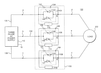
FIG. 1 is a schematic diagram, consistent with this invention, of a circuit
consisting of a three phase alternating current power supply for a load with a
solid-
state starter or controller;
FIG. 2 is a diagram of curves representing voltage across thyristor pair 104,
current through thyristor pair 104, and output voltages of power supply 112,
all shown
in FIG. 1, during normal and failure conditions;
FIG. 3 is a block diagram of a computer and a more detailed circuit diagram of
thyristor pair 104 in parallel with a first fault detector 110 as shown in
FIG. 1; and
FIG. 4 is a flow chart, consistent with this invention, of a process for
detecting
failed thyristors in a thyristor pair.
The following description of embodiments of this invention refer to the
accompanying drawings.
DESCRIPTION OF THE PREFERRED EMBODIMENT
FIG. 1 is a schematic diagram, consistent with this invention, of a three
phase
alternating current power supply 112 for a load 102 with a reduced voltage
solid state
starter or controller 150. Load 102 may comprise a three phase motor, which
may
drive various components of a refrigeration system. The refrigeration system
may
include a compressor, a condenser, a heat-exchanger, and an evaporator. As
mentioned above, starter 150 reduces the current supplied to load 102 in a
well-known
manner during start up or acceleration.
Three phase alternating current power supply 112 supplies load 102 via a first
power supply line 130, a second power supply line 132, and a third power
supply line
CA 02379957 2002-O1-18
WO 01/13487 PCT/US00/21649
4
136. Each line carries alternating current, but each has a different phase
angle. Line
130 has a first thyristor pair 104, comprising a first thyristor 142 and a
second
thyristor 144. Thyristors 142 and 144 are connected "back-to-back," i.e., the
anode of
thyristor 142 is connected to the cathode of thyristor 144, and vice versa.
Similar to
line 130, line 132 has a second back-to-back thyristor pair 106, and line 136
has a
third back-to-back thyristor pair 108. Control circuitry for timing and
triggering
thyristor pairs 104, 106, and 108, is well-known and is not shown.
A resistor 152 and a capacitor 154 are connected in series, in parallel with
thyristor pair 104. Resistor 152 and capacitor 154 provide a first "snubber
network"
to suppress high rates of change of voltage across thyristor pair 104.
Likewise, a
resistor 156 and a capacitor 158 provide a second snubber network for
thyristor pair
106. Also, a resistor 160 and a capacitor 164 provide a third snubber network
for
thyristor pair 108.
In systems consistent with this invention, a first fault detector 110 is in
parallel
with first thyristor pair 104, a second fault detector 114 is in parallel with
second
thyristor pair 106, and a third fault detector 116 is in parallel with third
thyristor pair
108. Each detector 110, 114, and 116 detects faults in thyristor pairs 104,
106, or 108,
respectfully.
FIG. 3 is a more detailed circuit diagram of thyristor pair 104 in parallel
with
first fault detector 110 as shown in FIG. 1. In systems consistent with this
invention,
first fault detector 110 comprises a bidirectional photo-coupler 310 in series
with a
capacitor 320 and a resistor 314. Bidirectional photo-coupler 310 comprises a
light
emitting diode (LED) pair 316, 318 arranged in a back-to-back configuration,
and an
optically-sensitive bipolar junction transistor (BJT) 308. The emitter of
transistor 308
is connected to the input of a microprocessor 326. A pull-down resistor 306 is
connected between ground and the emitter of transistor 308. The collector of
transistor 308 is connected to a separate power supply B+.
FIG. 3 also depicts a data processing system comprising a computer 332 that is
suitable for use with methods and systems consistent with this invention.
Computer
332 includes microprocessor 326, a memory 334, and a secondary storage device
CA 02379957 2002-O1-18
WO 01/13487 PCT/US00/21649
330. Memory 334 and secondary storage 330 may store application programs, such
as
an application 328, and data for execution and use by microprocessor 326.
The operation of fault detection circuit 110 is analyzed first when current Ia
through thyristor pair 104 is non-zero, and second when current Ia is zero.
5 In the first case, when current Ia is non-zero, either thyristor 142 or
thyristor
144 conducts and voltage Vad across thyristor pair 104 is the forward voltage
drop of
a thyristor, which is ideally zero. In this case, voltage Vad is insufficient
to allow
current to pass through detector 110 and LED pair 316, 318 do not emit a light
ray
322. As a result, optically-coupled transistor 308 does not turn on, and
transistor 308
outputs a logic low to microprocessor 326. Current Ia is non-zero when one of
thyristors 142, 144 is triggered and conducting properly or when one of
thyristors 142,
144 is shorted.
In the second case, when current Ia is zero, neither thyristor 142 nor
thyristor
144 conducts and the voltage across thyristor pair 104 is not necessarily
ideally zero,
unlike the first case. If load 102 is a three-phase motor, voltage Vad across
thyristor
pair 104 is equal to the difference between voltage supplied by power supply
112 at
point a and the back electromotive force (EMF) of the motor, provided the
motor is
rotating. Because input voltage supply 112 provides an AC source at point a,
the
absolute value of voltage Vad across thyristor 104 is significantly larger
than zero
twice per cycle.
Non-zero voltage Vad causes current to flow through first fault detector 110,
i.e., through resistor 314, capacitor 320, and LED 316 or LED 318. When
current
flows through detector 110, one of LED pair 316, 318 conducts and emits light
ray
322. Light ray 322 saturates the base of transistor 308, which conducts,
outputting a
logic high to microprocessor 326. Because of the AC power supply 112, there
are two
logic pulses every cycle of voltage at point a.
Capacitor 320 has a high impedance relative to resistor 314, which limits the
current through LED pair 316, 318, resistor 314, and capacitor 320. Thus, the
presence of capacitor 320 allows the power rating of resistor 314 to be small
by
preventing an undesirably large amount of current from flowing through fault
detector
110.
CA 02379957 2002-O1-18
WO 01/13487 PCT/US00/21649
6
Second fault detection circuit 114, and third fault detection circuit 116
operate
similarly to first fault detection circuit 110. As described below,
microprocessor 326
analyzes the logic pulses from fault detection circuits 110, 114, and 116 to
detect if
any of thyristors 142-147 has failed.
Detection of Open Thyristor Failure During Motor Steady State Speed
Three phase power supply 112 outputs sinusoidal voltages on lines 130, 132,
and 136 that have positive half cycles and negative half cycles, each at a
different
phase angle. FIG. 2 is a diagram of curves representing a voltage Vab between
lines
130 and 132, and a voltage Van between line 130 and ground of three phase
power
supply 112 in FIG. 1. Curve 201 represents line-to-line voltage Vab between
line 130
and 132 between points a and b in FIG. 1. Curve 203 represents line-to-neutral
voltage Van between line 130 and ground. The voltage on line 130 at point a
leads
the voltage on line 132 at point b by 120 °, which leads the voltage on
line 136 at point
c by 120 ° (a-b-c rotation).
If load 102 is a motor operating at steady state speed, starter 150 delivers
full
current from power supply 112 to the motor. When voltage Vab is in a positive
half
cycle, thyristor 144 may be triggered as early as 30 degrees later (a-b-c
rotation), and
a load voltage Vde follows the positive half cycle of voltage Vab. When
voltage Vab
is in a negative half cycle, thyristor 142 may be triggered as early as 30
degrees later
(a-b-c rotation), and load voltage Vde follows the negative half cycle of
voltage Vab.
Thyristor pairs 106 and 108 operate similarly.
At steady state speed during normal operation, either thyristor 142 or
thyristor
144 is conducting at any time. Consequently, voltage Vad across thyristor pair
104
remains ideally zero. If one of the thyristors 142, 144 fails open, however,
the
absolute value of voltage Vad across thyristor pair 104 would be significantly
larger
than zero at some point during each cycle of input voltage Van, i.e., voltage
Vad
pulsates. The pulses in voltage Vad creates a logic pulse that is fed to
microprocessor
326. Microprocessor 326, under the direction of application 328, detects one
or more
logic pulses and signals an open thyristor failure in thyristor pair 104.
During steady state motor operation, methods and systems consistent with this
invention detect the voltage across the thyristor, and indicate an open
thyristor failure
CA 02379957 2002-O1-18
WO 01/13487 PCT/US00/21649
7
when the voltage across the thyristor does not remain below a threshold value
during a
predetermined period of time. The predetermined period of time may be a cycle
or
half a cycle of voltage Van, among other values.
During normal motor steady state operation, therefore, no current flows
through fault detector 110 because current Ia is never discontinuous. Thus, no
light is
emitted from LED pair 316, 318, and microprocessor 326 receives no logic
pulses
during normal operation.
In methods and systems consistent with this invention, it is not necessary to
know the exact value of voltage Vad across thyristor pair 104. It is only
important to
determine whether voltage Vad is continuously near zero volts, or whether it
is
pulsating at a value larger than the threshold value.
Microprocessor 326 may use a digital filter implemented in application
program 328 to determine the average value of voltage generated by photo-
coupler
310. If the average rises above a given threshold, an open thyristor
indication for
thyristor pair 104 is signaled.
Fault detectors 114 and 116 operate similarly to fault detector 110 in
detecting
faults in thyristor pairs 106 and 108, respectfully. Likewise, microprocessor
326 is
connected to fault detectors 114 and 116 to detect open thyristor failures in
during
motor steady state.
Detection of Shorted Thyristor Failure During Motor Acceleration
If load 102 were a motor accelerating during startup, however, thyristors 142
and 144 are triggered in a delayed manner to control the current delivered to
the
motor. Referring again to FIG. 2, curves 202 and 204 represent current Ia
through
line 130 while thyristor pair 104 is triggered in a delayed manner at an angle
a to
reduce current delivered to load 102, assuming load 102 is resistive. Curves
206 and
208 represent voltage Vad across thyristor pair 104 while the thyristor pair
is triggered
in a delayed manner at an angle a. Curves 202 and 206 represent normal
operation,
and curves 204 and 208 represent operation during shorted thyristor failure.
When voltage Van is in a positive half cycle and thyristor 144 is not fired
during angle a, then current Ia remains zero as shown by portion 212 of curve
202.
When thyristor 144 is fired after angle a, then thyristor 144 conducts and
current Ia
CA 02379957 2002-O1-18
WO 01/13487 PCT/US00/21649
8
increases as shown by area 220 under curve 202. When Van is in the negative
half
cycle and thyristor 142 is not fired during angle a, then current Ia is zero,
as shown by
portion 214 of curve 202. When thyristor 142 is fired at angle a, then
thyristor 142
conducts and current Ia decreases as shown by area 210 under curve 202. During
delay angle a, voltage Vad across thyristor pair 104 is equal to voltage Van
because
load 102 is resistive. If load 102 were a three phase motor, Vad would equal
voltage
Van minus the back electromotive force (EMF) of the motor during the delay
angle a.
In FIG. 2, curve 204 represents current Ia when thyristor 142 fails short
while
thyristor pair 104 is triggered in a delayed manner at an angle a to reduce
current
delivered to load 102. Curve 208 represents voltage Vad across the thyristor
pair 104
when thyristor 142 fails shorted while thyristor pair 104 is triggered in a
delayed
manner at an angle a to reduce current delivered to load 102. When Van is in
its
positive half cycle, current Ia is non-zero and positive, no matter whether
one of
thyristors 142, 144 is triggered or not, as shown by area 216 under curve 204.
Similarly, when Van is in its negative half cycle, current Ia is non-zero and
negative,
no matter whether either of thyristors 142, 144 is triggered or not, as shown
by area
218 under curve 204. Voltage Vad across thyristor pair 104 is equal to zero
all the
time, due to shorted thyristor 144, as shown by curve 208.
As shown above, during motor acceleration, when thyristor pair 104 operates
properly with a large angle a, current Ia is discontinuous. In other words,
current Ia is
zero for a portion of time immediately before it changes polarity. It is noted
that
curves 201-208 are for when load 102 is resistive. A resistive load is chosen
for
illustration purposes. If load 102 were a motor, the curves would not be the
same, but
would be similar, and the operation of this invention would not change.
During motor acceleration, therefore, LED pair 316, 318 emit light pulse 322
twice during every full cycle of input current from power supply 112. Thus,
during
motor acceleration, microprocessor 326 should receive two logic pulses for
every
cycle of power supply 112 input on line 130 if thyristors 142, 144 operate
properly.
If load 102 were a motor, during motor acceleration the voltage across
thyristor pair 104 pulsates, that is, it remains zero when thyristor pair 104
conducts
and non-zero when thyristor pair 104 does not conduct. When one of the
thyristors
CA 02379957 2002-O1-18
WO 01/13487 PCT/US00/21649
9
142, 144 fails short, however, the pulsing ceases and the circuit output
remains
ideally zero, indicating a shorted thyristor of thyristor 142 or 144.
Thus, methods and systems consistent with this invention detect the voltage
across thyristor pair 104. Methods and systems consistent with this invention
indicate
a shorted thyristor when microprocessor 326 determines that the voltage across
thyristor pair does not pulse for a period of time during startup. Methods and
systems
consistent with this invention indicate a failed short thyristor when the
voltage across
the thyristor remains below a threshold value during the period of time during
motor
startup. The period of time may be a cycle or a half cycle, among other
values.
The duration of the pulses is a function of the delay angle a. Microprocessor
326 uses a digital filter implemented in application program 328 to determine
the
average value of voltage generated by photo-coupler 310. If the average falls
below a
given threshold, a shorted thyristor indication for thyristor pair 104 is
signaled.
Fault detectors 114 and 116 operate similarly to fault detector 110 in
detecting
faults in thyristor pairs 106 and 108, respectfully. Likewise, microprocessor
326 is
connected to fault detectors 114 and 116 to detect short thyristor failures
during motor
acceleration.
Detection of Shorted Thyristor Failure Prior to Motor Startup
If load 102 is a motor, then prior to motor startup the motor is turned off,
i.e.,
no thyristors are turned on. The motor behaves as a low impedance between each
of
the three supply lines 130, 132, and 136 from starter 150. The impedance of
the first
snubber network is much lower than the impedance of the failure detectors 110,
but
the impedance of first snubber network is much higher than the impedance of
the
motor when stopped. Thus, prior to motor startup, voltage Vad across failure
detectors 110 is sinusoidal, and equal to voltage Van divided by the square
root of
three. Thus, one of LED pair 316, 318 conducts, and transistor 308 outputs a
logic
high.
If one of thyristors 142, 144 fails short, however, voltage Vad is ideally
zero
and transistor 308 outputs a logic low. Thyristor failure detection for
thyristor pairs
106 and 108 operate similarly.
CA 02379957 2002-O1-18
WO 01/13487 PCT/US00/21649
Methods and systems consistent with this invention detect voltage Vad across
thyristor pair 104. If voltage Vad is continuously small compared to Van, a
shorted
thyristor is signaled. Similarly, methods and systems consistent with this
invention
also detect voltage Vbe across thyristor pair 106 and voltage Vcf across
thyristor pair
5 108 to detect whether thyristors 145-148 failed short prior to motor
startup.
FIG. 4 is a flow chart, consistent with this invention, of a process 400 for
detecting failed thyristors in thyristor pair 104. In FIG. 3, memory 334
stores
application 328 used to implement process 400.
First, systems and methods consistent with this invention determine whether
10 the motor is in steady state (step 402). If the motor is in steady state,
methods or
systems consistent with this invention detect voltage Vad across thyristor
pair 104
(step 404) and determine whether voltage Vad is pulsating (step 406). If the
voltage is
pulsating, then an open thyristor failure is signaled (step 408). If voltage
Vad is not
pulsating, then no failure is signaled (step 410).
Systems and methods consistent with this invention determine whether the
motor is accelerating (step 412). If the motor is accelerating, methods or
systems
consistent with this invention detect voltage Vad across thyristor pair 104
(step 414)
and determine whether voltage Vad is pulsating (step 416). If the voltage is
pulsating,
then no failure is signaled (step 418). If voltage Vad is not pulsating, then
a shorted
thyristor failure is signaled (step 420).
Systems and methods consistent with this invention determine whether the
motor is turned off (step 422). If the motor is turned off, methods and
systems
consistent with this invention detect voltage Vad across thyristor pair 104
(step 424)
and determine whether it is non-zero, or small compared to Van (step 426). If
the
voltage is non zero, then no failure is detected (step 428). If voltage Vad is
zero, then
a shorted thyristor failure is signaled (step 430).
Systems and methods consistent with this invention apply the steps of process
400 to a voltage Vbe across thyristor pair 106 in supply line 132 and to a
voltage Vcf
across thyristor pair 108.
Those skilled in the art recognize that various modifications and variations
can
be made in the preceding examples without departing from the scope or spirit
of the
WO 01/13487 CA 02379957 2002-O1-18 pCT/US00/21649
11
invention. For example, even though the most commonly used controlled
rectifier is
the thyristor, any controlled rectifiers would suffice. Further, it is
possible that the
load be other than a motor; methods and systems consistent with this invention
work
with any type of load.
The description of the invention does not limit the invention. Instead, it
provides examples and explanations to allow persons of ordinary skill to
appreciate
different ways to practice the invention. The following claims define the true
scope
and spirit of the invention.