Note: Descriptions are shown in the official language in which they were submitted.
CA 02380030 2009-11-23
30400-1
INSERT FOR PRESSURIZED LIQUID CONTAINERS, IN PARTICULAR, BEVERAGE
CONTAINERS
BACKGROUND OF THE INVENTION
1. Field of the Invention
The invention relates to an insert for pressurized
containers for liquids, in particular, beverage containers.
The insert comprises a component chamber for receiving a
liquid, paste-like, powder-like or solid component, for
example, a flavoring agent, coloring agent, or other agents.
The insert moreover comprises a pressure chamber as a means
for introducing the component into the liquid when opening
the container for liquids, wherein the pressure chamber has a
small outer bore.
2. Description of the Related Art
The introduction of a component or active substance into
a liquid with the goal of changing the properties of this
liquid in a certain way is known for different fields of
application. In this connection, generally two different
applications are to be differentiated, in particular:
the introduction of the active substance into the liquid
already during manufacture of the final product, for
example, the introduction of coloring or flavoring
agents in the manufacture of beverages such as sodas,
1
CA 02380030 2009-11-23
30400-1
liquor, etc.;
the introduction of the active substance only upon using
or consuming the liquid, for example, the introduction
of milk and sugar into coffee which has been previously
prepared.
For introducing the active substance already during the
manufacture of the liquid, known devices, such as, for
example, metering pumps or weighing devices, are employed
which have to meter correspondingly large quantities
depending on the manufacturing process. The introduction of
the active substance into the liquid with delay after the
production process, wherein the point in time of the
introduction of the active substance can be selected freely,
presents the difficulty of metering, depending on the amount
of liquid, correspondingly small amounts of active substance
and of storing the liquid and the active substance separate
from one another and of bringing them into contact only as
needed.
From European patent document 0 965 536 an insert for
receiving a solid, paste-like, or liquid agent, for example,
a coloring agent or a flavoring agent, for use in beverage
containers is known for the purpose of a metered introduction
of this agent into a beverage. The introduction of the
2
CA 02380030 2009-11-23
30400-1
active substance is.carried out automatically when opening
the beverage container which is pressurized by gas pressure.
The known active substance container is cylindrical and of a
stepped configuration with two chambers and with a dispensing
opening. It is connected fixedly to the inner bottom of the
beverage container. The configuration and the introduction
of the insert or active substance container are relatively
complex and cost-intensive, and, moreover, this insert is
neither suitable for all types of containers for liquids nor
for special applications.
3
CA 02380030 2009-11-23
30400-1
SUMMARY OF THE INVENTION
It is an object of some embodiments of the present
invention to provide an insert for pressurized containers
for liquids, in particular, beverage containers, with which
in a simple way any suitable component or active substance
can be introduced into a liquid wherein the introduction is
to take place automatically at any desired point in time and
then quickly, i.e., without long-term action, and
automatically, and wherein storage of the active substance
separate from the liquid is not required.
In accordance with an aspect of the present
invention, this is achieved in that the insert is freely
movable in the container for liquids but has such a stable
floating position on the surface of the liquid within the
container for the liquids but has such a stable floating
position on the surface of the liquid within the container
for the liquids that the outer bore always points upwardly
and, in this way, optimizes a pressure compensation with the
environment, wherein, after opening the container for
liquids, the then resulting relative overpressure in the
pressure chamber in relation to the decreased pressure in
the container for liquids effects an opening of the
component chamber.
4
CA 02380030 2009-11-23
30400-1
In this way, it is ensured that the insert, after
introduction into the container for the liquids and closing
the container, the pressure build-up in the pressure chamber
of the insert is realized without problems and, when later on
opening the container for liquids, the insert also-opens
without problems and releases-the active substance from the
component chamber. A separate storage of the active
substance is not required because the active substance,
spatially still separate from the liquid,. is however
contained in the same container. Metering is also no problem
because the active substance container contains exactly the
amount of active substance which is to be introduced.
Applications for the subject matter of the invention are
the following:
- syrup to be introduced into beer, for example, top-
fermented beer such as "Berliner Weisse"
- vitamin components for juices
- components for long drinks
- cocoa powder for milk
- flavoring agents for milk shakes
- plant fertilizer in liquid
- digestive aid in liquid
salts of any type in liquid.
CA 02380030 2009-11-23
30400-1
Gases which can. be used in the form of their gas volume
to maintain the required overpressure in the liquid or
beverage containers,. such as soda or beer containers, as well
as during their consumption are preferably carbon dioxide,
nitrogen, but also air and all noble gases in any suitable
mixing ratio-
For the purpose of simplifying manufacture, it is
advantageously provided according to the invention that the
insert is comprised of an elongate insert, member which is
provided with a lid on one side.
Moreover, it is provided that the insert member has an
identical cross-section over its length with a median point
of the surface area or a median point axis or median point
line displaced to one side, wherein the outer bore is
arranged at the location which is farthest removed from the
median point of the insert member in the outer wall.
Moreover, it can be expedient when several outer bores are
provided in the outer wall of the insert member.
Especially expedient is an insert that is droplet-shaped
in cross-section. Alternatively, the insert in cross-section
may be approximately egg-shaped.
6
CA 02380030 2009-11-23
30400-1
According to a further embodiment of the
invention, the component chamber in the insert is
cylindrical and completely enclosed by the pressure chamber.
Advantageously, the lid for this purpose has an annular
groove which is engaged by the end of the wall of the
component chamber in the closed state. With this measures,
a problem-free assembly of the individual parts as well as a
simple and problem-free opening of the component chamber are
ensured.
Since the quantity of the active substance to be
introduced into the liquid can vary according to the
specific need, the size of the component chamber containing
the active substance is adjustable.
A further aspect of the present invention provides
an insert for liquid containers disposed under pressure,
which insert is freely movable in the liquid container, the
insert comprising: in insert body having an outer wall; the
insert body enclosing a component chamber for receiving a
liquid, pasty, pulverulent or solid component, and a
pressure chamber as a means for induction of the component
into the liquid on opening of the liquid container; the
pressure chamber having, for optimized pressure equalization
with the pressure of the liquid container, a small outer
bore which in a stable floating position always faces
upwardly and is thus constantly disposed above the level of
liquid in the liquid container, wherein: (a) for producing
an asymmetrical center of gravity and the thereby created
stable floating position of the insert, the insert body
having a drop-shaped or egg-shaped cross-section over an
entire longitudinal axis and a rectangular cross-section
7
CA 02380030 2009-11-23
30400-1
perpendicular to the longitudinal axis, and (b) the outer
bore is arranged at a position in the outer wall of the
insert body at which the spacing of the outer bore from the
center of gravity of the associated drop-shaped or egg-
shaped cross sectional area is a maximum.
Another aspect of the present invention provides
an insert for insertion into a container for liquids under
pressure, which insert is freely movable in the container,
the insert comprising an insert member having an outer wall,
the insert member defining a component chamber for receiving
an active substance, a pressure chamber for effecting an
introduction of the active substance into the liquid when
the container is opened, wherein a pressure of the pressure
chamber is in an equilibrium with the pressure of the
container through a small outer bore in the pressure
chamber, the insert which is freely moveable within the
container on a surface of the liquid assumes a stable
floating position, so that the outer bore is always located
above the liquid level and causes an optimized pressure
equalization of the pressure chamber and the pressure of the
container, wherein the insert member has an asymmetrical
center of gravity and a drop-shaped or egg-shaped cross-
section along an entire longitudinal axis of the insert
member from a lid to an opposing outer wall so as to produce
an asymmetrical center of gravity which creates the stable
floating position, perpendicular to the longitudinal axis
the insert member has a rectangular cross-section, the lid
simultaneously closes the pressure chamber and the component
chamber, and in the stable floating position of the insert
makes possible a horizontal discharge of the components into
8
CA 02380030 2009-11-23
30400-1
the liquid, wherein the component chamber is cylindrical and
arranged parallel to the longitudinal axis of the insert
member so as to sustain the asymmetrical center of gravity
of the insert member, wherein the outer bore is located in
the outer wall at a position farthest removed from the
center of gravity of an area of the drop-shaped or egg-
shaped cross-section.
8a
-CA 02380030 2002-04-02
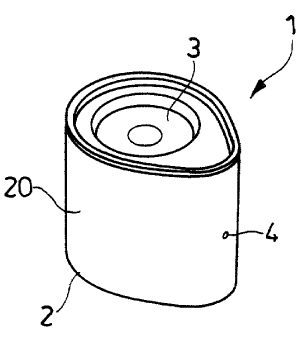
BRIEF DESCRIPTION OF THE DRAWING
In the drawing:.
Fig. 1 is a perspective view of the insert according to
the invention;
Fig. la is a perspective view onto the lid of the insert
according to Fig. 1;
Fig. lb is a perspective view of the insert. according to
Fig. 1 in the open state without lid
Fig. 2 is a plan view onto the insert according to Fig.
1;
Fig. 3 shows a section along the line A'A of Fig. 2;
Fig. 4 shows a greatly enlarged illustration of Fig. .3.
9
CA 02380030 2002-04-02
DESCRIPTION OF THE PREFERRED EMBODIMENTS
In Figs. 1 through 4 one example of an applicationof
the insert 1 according to the invention for pressurized
containers for liquids, preferably beverage containers (not
illustrated), is.shown. The insert is comprised substantially
of an insert member 2 with a-lid 3 wherein the insert member
2 is provided in its outer wall 20 with an outer bore 4.
According to Figs. lb, 3, and 4, the insert member 2 has
a component chamber 5 for receiving an active substance in
the form of a component that is liquid, paste-like, powder-
like or solid, for example, a flavoring agent, coloring
agent, or other active substance; moreover, a pressure
chamber 6 is provided as a means for introducing the
component into the liquid when opening the liquid container
and the lid 3 is separated from the insert member 2.
The component chamber 5 in the insert 1 is cylindrical
and surrounded by the pressure chamber 6, separated by the
partition 50. Especially expediently, the lid 3 has an
annular groove 30 which is engaged by one end of the wall 50
of the component chamber 5 in the closed state. The annular
groove 30 is arranged between the sidewall 32 of a circular
recess 31 and an outer annular collar 33 so that a canting-
CA 02380030 2002-04-02
free blast-off of the lid 3 is ensured. For a simple and
safe assembly, the lid 3 can be'snapped into place with its
periphery 34 into the outer wall 20 of the insert member 2.
The elongate insert member 2 illustrated in the Figures
is shown to have identical cross-section over its -length and
has a median point of the surface area (cross-section) or
median point axis or line moved to one side (see particularly
Fig. 2) wherein the outer bore 4 is arranged at a location of
its outer wall 20 which is farthest removed from the median
point of the insert member 2.
The insert 1 with the component or active substance is
introduced into the beverage container, for example, a soda
or beer can or bottle. Since the insert 1 floats and is
configured such that the small outer bore 4 always points
upwardly, and is thus positioned in the area where the CO2
collects, pressure compensation is enabled via the small bore
4 after closing the container. When the beverage container
is opened, resulting in a sudden inner pressure loss, a
pressure compensation of the gases in the pressure chamber 6
still under overpressure cannot be realized only via the
small bore 4 in a short period of time. The result is that
by means of the still present gas pressure relative to the
now pressure-relieved surroundings, the lid 3 is blasted off
11
CA 02380030 2002-04-02
and the component chamber 5. opens. In this way, the active
substance or component, in the form of a liquid, a powder, a
paste or a solid, to be mixed with the liquid is introduced
into the liquid surrounding the insert 1. By shaking the
container, an even more intensive mixing of the liquid with
the active substance is possible so th.t in a very- short
period of time the desired final product is obtained.
By using the insert 1 according to the invention, a
possibility is provided to store a liquid, together with an
active substance required for the end use or with one or
several desired components with the advantage that the
metering step is carried out automatically when opening the
beverage container. Moreover, errors due to wrongly metered
quantities or as a result of a premature metering before the
end use can no longer occur.
The features and configurations according to the
invention are not limited to the embodiment illustrated in
the drawings. Possible variations of the insert 1 according
to the invention for containers for liquids can reside in
that, for example, the insert 1 and/or the chambers 5, 6
arranged therein have different suitable cross-sectional
shapes and that, for example, several separate component (5)
and/or pressure chambers 6 are provided adjacent to one
12
CA 02380030 2002-04-02
another with different opening features. The respective
constructive configuration is left up to a person skilled in
the art.
While specific embodiments of the invention have been
shown and described in detail to illustrate the inventive
principles, it will be understood that the invention may be
embodied otherwise without departing from such principles.
13