Language selection

Search

Patent 2380146 Summary

Third-party information liability

Some of the information on this Web page has been provided by external sources. The Government of Canada is not responsible for the accuracy, reliability or currency of the information supplied by external sources. Users wishing to rely upon this information should consult directly with the source of the information. Content provided by external sources is not subject to official languages, privacy and accessibility requirements.

Claims and Abstract availability

Any discrepancies in the text and image of the Claims and Abstract are due to differing posting times. Text of the Claims and Abstract are posted:

  • At the time the application is open to public inspection;
  • At the time of issue of the patent (grant).
(12) Patent: (11) CA 2380146
(54) English Title: HIGH VOLTAGE FUSE
(54) French Title: FUSIBLE HAUTE TENSION
Status: Term Expired - Post Grant Beyond Limit
Bibliographic Data
(51) International Patent Classification (IPC):
  • H01H 85/54 (2006.01)
  • H01H 85/042 (2006.01)
  • H01H 85/30 (2006.01)
(72) Inventors :
  • BORCHARDT, GLENN R. (United States of America)
  • MONTANTE, JORGE R. (United States of America)
  • WARSZAWA, MARTIN A. (United States of America)
(73) Owners :
  • S&C ELECTRIC COMPANY
(71) Applicants :
  • S&C ELECTRIC COMPANY (United States of America)
(74) Agent: OSLER, HOSKIN & HARCOURT LLP
(74) Associate agent:
(45) Issued: 2011-01-04
(22) Filed Date: 2002-04-03
(41) Open to Public Inspection: 2003-09-02
Examination requested: 2007-03-14
Availability of licence: N/A
Dedicated to the Public: N/A
(25) Language of filing: English

Patent Cooperation Treaty (PCT): No

(30) Application Priority Data:
Application No. Country/Territory Date
60/361,601 (United States of America) 2002-03-02

Abstracts

English Abstract

A fuse is provided that is suitable for operation in unusual environments and includes an operation indicator that is simple and reliable. A movable arcing tube is released during operation. As the arcing tube moves outside the fuse assembly, a latching spring moves into a receiving groove in the arcing tube to retain the arcing tube in the external operated position.


French Abstract

Fusible conçu pour fonctionner dans des environnements inhabituels et comprenant un indicateur de fonctionnement simple et fiable. Un tube de production d'arc mobile est libéré pendant le fonctionnement. Lorsque le tube de production d'arc sort du fusible, un ressort de verrouillage se déplace dans une rainure de réception située à l'intérieur du tube de production d'arc de manière à maintenir ce dernier dans la position externe.

Claims

Note: Claims are shown in the official language in which they were submitted.

The embodiments of the invention in which an exclusive property or privilege
is claimed
are defined as follows:
1. A fuse comprising a housing and a fuse link assembly, the fuse link
assembly including a movable tube that is relatively movable with respect to
the
housing portion during a fuse operation, the fuse further comprising indicator
means for
retaining the movable tube in a predetermined indicating position after fuse
operation,
said indicator means comprising first means carried by the housing portion and
second
means carried by the movable tube cooperating to retain the tube in the
predetermined
indicating position, said first means comprising a circumferentially biased
member
positioned about said movable tube, said second means comprising a receiving
portion.
2. The fuse of claim 1 wherein said housing includes a housing tube and
said movable tube being disposed within said housing tube.
3. The fuse of claim 2 wherein said fuse link assembly further comprises a
fusible element that operates in accordance with predetermined characteristics
and
being arranged to retain said movable tube against movement and release siad
movable tube upon operation.
4. The fuse of claim 3 wherein said fuse link assembly further comprises a
resilient element for storing energy to move said movable tube after operation
of said
fusible element.
5. The fuse of claim 4 wherein said fuse link assembly further comprises a
cover in which said resilient element is disposed, said cover being relatively
movable
with respect to the housing.
6. The fuse of claim 5 wherein a sealing element is provided between said
cover and said housing.
-5-

7. The fuse of claim 2 further comprising resilient biasing means for biasing
said movable tube to move with respect to said housing, said fuse link
assembly further
comprising means for providing a seal between said housing tube and said fuse
link
assembly and for retaining said fuse link assembly against movement with
respect to
said housing.
-6-

Description

Note: Descriptions are shown in the official language in which they were submitted.


CA 02380146 2002-04-03
SC-5339-C
HIGH VOLTAGE FUSE
BACKGROUND OF THE INVENTION
Field of the Invention
The present invention relates generally to high voltage fuses and more
particularly to a fuse suitable for operation in unusual environments and
including an
operation indicator.
Description of the Related Art
Various types of high voltage fuses are known having diverse construction. The
fuae shown in U.S. Patent No. 5,502,427 includes a fuse cartridge coupled to a
spring
assembly positioned within a fuse tube. The fuse shown in U.S. Patent No.
4,344,059
includes an arcing rod moving within a conductive fuse tube with the arcing
rod being
engaged by a catcher when the arcing rod moves during fuse operation so that
the
arcing rod will not bounce back or reverse direction during and after fuse
operation.
Tree catcher includes angled fingers that interact to capture a flange carried
by the
arcing rod. U.S. Patent No. 4,058,784 illustrates an indicator-equipped fuse
where the
indicator that moves outside the casing of the fuse. The fuse in U.S. Patent
No.
4,296,397 is suited for a corrosive atmosphere so as to maintain a non-
conductive path
afi:er operation.
While the fusible elements of the prior art may be generally suitable for
their
intended uses, they do not provide a compact fuse for use in unusual
environments and
including an operation indicator.
SUMMARY OF THE INVENTION
Accordingly, it is a principal object of the present invention to provide a
fuse
suitable for operation in unusual environments and including an operation
indicator.
These and other objects of the present invention are efficiently achieved by a
fuse that is suitable for operation in unusual environments and includes an
operation
indicator that is simple and reliable. A movable arcing tube is released
during
operation. As the arcing tube moves outside the fuse assembly, a latching
spring
-1-

CA 02380146 2002-04-03
SC-5339-C
moves into a receiving groove in the arcing tube to retain the arcing tube in
the external
o~>erated position.
BRIEF DESCRIPTION OF THE DRAWING
S The invention, both as to its organization and method of operation, together
with
further objects and advantages thereof, will best be understood by reference
to the
specification taken in conjunction with the accompanying drawing in which:
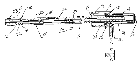
FIG. 1 is an elevational view, partly in section, of a fuse in accordance with
the
present invention;
FIG. 2 is a sectional view of a fuse link assembly of the fuse of FIG. 1;
FIG. 3 is an elevational view ~of an arcing tube of the fuse link assembly of
FIG.
2;
FIG. 4 is an elevational view of a lower terminal of the fuse link assembly of
FIG.
2;
FIG. 5 is an enlarged partial view of the lower terminal of FIG. 4; and
FIG. 6 is an elevational view o~f a latching spring member of the fuse of FIG.
1.
DETANLED DESCRIPTION
Referring now to FIGS. 1-6, a fuse 10 in accordance with the present invention
includes a fuse link assembly 12 (alao see FIG. 2) carried within an outer
tube 14 and
supported with respect to an electrocle mounting assembly 16. The outer tube
provides
a dielectric and physical barrier to the operating environment external to the
fuse link
assembly 12. The electrode mounting assembly 16 provides electrical connection
to an
arcing tube 18 of the fuse link assembly 12 that is slidably received within
the electrode
mounting assembly 16. The electrode mounting assembly 16 also forms an upper
terminal for connection to an electrical system. A lower terminal 20 of the
fuse link
assembly 12 provides electrical connection to protected equipment (not shown)
via a
contact 23, similar to that as shown in U.S. Patent No. 5,502,427. A strain
wire 22
provides a mechanical and electrical connection between the arcing tube or
upper
terminal 18 and the lower terminal 20, the strain wire 22 also functioning as
a fusible
elE~ment to provide the fusing characteristics of the fuse 10. The strain wire
22 is
retained at a lower end to the lower terminal 20 at 25 and to the arcing tube
18 at an
upper end at 27, e.g. via a swaging operation or the like. The arcing tube 18
is secured
wivlh respect to the electrode mounting assembly 16 via an upper housing
element 24
-2-

CA 02380146 2002-04-03
SC-5339-C
and a retaining element 26 that is affixed to the upper end of the arcing
tube, e.g. in a
specific embodiment, the retaining element 26 is a pop rivet. In a specific
embodiment,
a sealing compound is applied between the upper housing element 24 and the
retaining
element 26. The upper housing element 24 is movable with respect to the
electrode
mounting assembly 16 and may allso be characterized as a portion of the fuse
link
assembly. A spring 28 is disposed about the arcing tube 18 and within the
upper
housing element 24, operating against the electrode mounting assembly 16.
Normally,
the spring 28 is in compression. When the current between the electrode
mounting
assembly 16 and the lower terminal 20 and through the fuse link assembly 12
exceeds
a predetermined current, the stain wire 22 becomes disintegral and the spring
28 is
released thereby separating the arcing tube 18 and the lower terminal 20 of
the fuse
link assembly 12 and interrupting they current therethrough.
In accordance with important aspects of the present invention, the fuse 10 is
includes an operation indication facility also characterized as a blown-fuse
indicator.
Specifically, upon operation of the fuse 10, the arcing tube 18 moves to the
right in FIG.
1 with respect to the electrode mounting assembly 16 and is held in a
predetermined
operating position. To achieve this end, the arcing tube 18 includes a
circumferential
recessed portion or groove at 30 and a latching spring 35 (best seen in FIG.
6) that is
positioned within a bore 17 of a cylindrical housing portion 19 of the
electrode mounting
a~;sembly 16. A retaining washer 34~ is also provided along with an
elastomeric sealing
gasket 32 intermediate the latching spring 35 and the outer end of the bore
17. Thus,
when the arcing tube 18 moves to the right in FIG. 1, the latching spring 32
moves into
the groove 30 whereat and whereupon the arcing tube 18 is retained providing a
blown
fuae indication position. The upper housing element 24 moves with the arcing
tube 18
during operation. To this end, a sealing element 36 is provided intermediate
the upper
housing element 24 and the electrode mounting assembly 16. During normal
conditions, the seal is maintained via the tension in the spring 28. The outer
tube 14 is
retained and sealed at the lower end with respect to the lower terminal 20 via
the
provision of an O-ring sealing element 40 carried within a groove 44 of the
lower
terminal 20 along with a support washer 42that is retained by a snap ring 45
carried
within a groove 46 of the lower terminal 20 (best seen in FIG. 5.
While there has been illustrated and described a preferred embodiment of the
prcaent invention, it will be apparent that various changes and modifications
will occur
to those skilled in the art. Accordingly, it is intended in the appended
claims to cover all
-3-

CA 02380146 2002-04-03
SC-5339-C
such changes and modifications that fall within the true spirit and scope of
the present
invention.
-4-

Representative Drawing
A single figure which represents the drawing illustrating the invention.
Administrative Status

2024-08-01:As part of the Next Generation Patents (NGP) transition, the Canadian Patents Database (CPD) now contains a more detailed Event History, which replicates the Event Log of our new back-office solution.

Please note that "Inactive:" events refers to events no longer in use in our new back-office solution.

For a clearer understanding of the status of the application/patent presented on this page, the site Disclaimer , as well as the definitions for Patent , Event History , Maintenance Fee  and Payment History  should be consulted.

Event History

Description Date
Inactive: Expired (new Act pat) 2022-04-04
Common Representative Appointed 2019-10-30
Grant by Issuance 2011-01-04
Inactive: Cover page published 2011-01-03
Inactive: Final fee received 2010-10-19
Pre-grant 2010-10-19
Notice of Allowance is Issued 2010-10-06
Letter Sent 2010-10-06
Notice of Allowance is Issued 2010-10-06
Inactive: Approved for allowance (AFA) 2010-10-04
Amendment Received - Voluntary Amendment 2010-02-26
Inactive: S.30(2) Rules - Examiner requisition 2009-09-01
Letter Sent 2007-04-17
Request for Examination Received 2007-03-14
Request for Examination Requirements Determined Compliant 2007-03-14
All Requirements for Examination Determined Compliant 2007-03-14
Application Published (Open to Public Inspection) 2003-09-02
Inactive: Cover page published 2003-09-01
Letter Sent 2003-07-23
Inactive: Single transfer 2003-06-17
Inactive: IPC assigned 2002-06-18
Inactive: First IPC assigned 2002-06-18
Inactive: IPC assigned 2002-06-18
Inactive: Courtesy letter - Evidence 2002-05-14
Inactive: Filing certificate - No RFE (English) 2002-05-08
Application Received - Regular National 2002-05-08

Abandonment History

There is no abandonment history.

Maintenance Fee

The last payment was received on 2010-03-31

Note : If the full payment has not been received on or before the date indicated, a further fee may be required which may be one of the following

  • the reinstatement fee;
  • the late payment fee; or
  • additional fee to reverse deemed expiry.

Patent fees are adjusted on the 1st of January every year. The amounts above are the current amounts if received by December 31 of the current year.
Please refer to the CIPO Patent Fees web page to see all current fee amounts.

Owners on Record

Note: Records showing the ownership history in alphabetical order.

Current Owners on Record
S&C ELECTRIC COMPANY
Past Owners on Record
GLENN R. BORCHARDT
JORGE R. MONTANTE
MARTIN A. WARSZAWA
Past Owners that do not appear in the "Owners on Record" listing will appear in other documentation within the application.
Documents

To view selected files, please enter reCAPTCHA code :


To view images, click a link in the Document Description column (Temporarily unavailable). To download the documents, select one or more checkboxes in the first column and then click the "Download Selected in PDF format (Zip Archive)" or the "Download Selected as Single PDF" button.

List of published and non-published patent-specific documents on the CPD .

If you have any difficulty accessing content, you can call the Client Service Centre at 1-866-997-1936 or send them an e-mail at CIPO Client Service Centre.

({010=All Documents, 020=As Filed, 030=As Open to Public Inspection, 040=At Issuance, 050=Examination, 060=Incoming Correspondence, 070=Miscellaneous, 080=Outgoing Correspondence, 090=Payment})


Document
Description 
Date
(yyyy-mm-dd) 
Number of pages   Size of Image (KB) 
Representative drawing 2002-07-03 1 12
Abstract 2002-04-02 1 12
Description 2002-04-02 4 179
Claims 2002-04-02 2 54
Drawings 2002-04-02 2 43
Description 2010-02-25 4 177
Claims 2010-02-25 1 49
Representative drawing 2010-12-08 1 12
Filing Certificate (English) 2002-05-07 1 165
Request for evidence or missing transfer 2003-04-06 1 104
Courtesy - Certificate of registration (related document(s)) 2003-07-22 1 106
Reminder of maintenance fee due 2003-12-03 1 109
Reminder - Request for Examination 2006-12-04 1 118
Acknowledgement of Request for Examination 2007-04-16 1 176
Commissioner's Notice - Application Found Allowable 2010-10-05 1 163
Correspondence 2002-05-07 1 29
Fees 2004-04-04 1 34
Fees 2005-04-03 1 34
Fees 2006-04-02 1 41
Fees 2007-04-02 1 41
Fees 2008-04-02 1 42
Fees 2009-04-02 1 47
Fees 2010-03-30 1 41
Correspondence 2010-10-18 1 41