Sélection de la langue

Search

Sommaire du brevet 2380146 

Énoncé de désistement de responsabilité concernant l'information provenant de tiers

Une partie des informations de ce site Web a été fournie par des sources externes. Le gouvernement du Canada n'assume aucune responsabilité concernant la précision, l'actualité ou la fiabilité des informations fournies par les sources externes. Les utilisateurs qui désirent employer cette information devraient consulter directement la source des informations. Le contenu fourni par les sources externes n'est pas assujetti aux exigences sur les langues officielles, la protection des renseignements personnels et l'accessibilité.

Disponibilité de l'Abrégé et des Revendications

L'apparition de différences dans le texte et l'image des Revendications et de l'Abrégé dépend du moment auquel le document est publié. Les textes des Revendications et de l'Abrégé sont affichés :

  • lorsque la demande peut être examinée par le public;
  • lorsque le brevet est émis (délivrance).
(12) Brevet: (11) CA 2380146
(54) Titre français: FUSIBLE HAUTE TENSION
(54) Titre anglais: HIGH VOLTAGE FUSE
Statut: Durée expirée - au-delà du délai suivant l'octroi
Données bibliographiques
(51) Classification internationale des brevets (CIB):
  • H01H 85/54 (2006.01)
  • H01H 85/042 (2006.01)
  • H01H 85/30 (2006.01)
(72) Inventeurs :
  • BORCHARDT, GLENN R. (Etats-Unis d'Amérique)
  • MONTANTE, JORGE R. (Etats-Unis d'Amérique)
  • WARSZAWA, MARTIN A. (Etats-Unis d'Amérique)
(73) Titulaires :
  • S&C ELECTRIC COMPANY
(71) Demandeurs :
  • S&C ELECTRIC COMPANY (Etats-Unis d'Amérique)
(74) Agent: OSLER, HOSKIN & HARCOURT LLP
(74) Co-agent:
(45) Délivré: 2011-01-04
(22) Date de dépôt: 2002-04-03
(41) Mise à la disponibilité du public: 2003-09-02
Requête d'examen: 2007-03-14
Licence disponible: S.O.
Cédé au domaine public: S.O.
(25) Langue des documents déposés: Anglais

Traité de coopération en matière de brevets (PCT): Non

(30) Données de priorité de la demande:
Numéro de la demande Pays / territoire Date
60/361,601 (Etats-Unis d'Amérique) 2002-03-02

Abrégés

Abrégé français

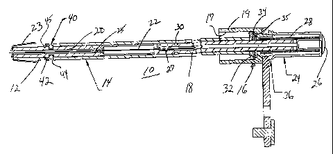
Fusible conçu pour fonctionner dans des environnements inhabituels et comprenant un indicateur de fonctionnement simple et fiable. Un tube de production d'arc mobile est libéré pendant le fonctionnement. Lorsque le tube de production d'arc sort du fusible, un ressort de verrouillage se déplace dans une rainure de réception située à l'intérieur du tube de production d'arc de manière à maintenir ce dernier dans la position externe.


Abrégé anglais

A fuse is provided that is suitable for operation in unusual environments and includes an operation indicator that is simple and reliable. A movable arcing tube is released during operation. As the arcing tube moves outside the fuse assembly, a latching spring moves into a receiving groove in the arcing tube to retain the arcing tube in the external operated position.

Revendications

Note : Les revendications sont présentées dans la langue officielle dans laquelle elles ont été soumises.


The embodiments of the invention in which an exclusive property or privilege
is claimed
are defined as follows:
1. A fuse comprising a housing and a fuse link assembly, the fuse link
assembly including a movable tube that is relatively movable with respect to
the
housing portion during a fuse operation, the fuse further comprising indicator
means for
retaining the movable tube in a predetermined indicating position after fuse
operation,
said indicator means comprising first means carried by the housing portion and
second
means carried by the movable tube cooperating to retain the tube in the
predetermined
indicating position, said first means comprising a circumferentially biased
member
positioned about said movable tube, said second means comprising a receiving
portion.
2. The fuse of claim 1 wherein said housing includes a housing tube and
said movable tube being disposed within said housing tube.
3. The fuse of claim 2 wherein said fuse link assembly further comprises a
fusible element that operates in accordance with predetermined characteristics
and
being arranged to retain said movable tube against movement and release siad
movable tube upon operation.
4. The fuse of claim 3 wherein said fuse link assembly further comprises a
resilient element for storing energy to move said movable tube after operation
of said
fusible element.
5. The fuse of claim 4 wherein said fuse link assembly further comprises a
cover in which said resilient element is disposed, said cover being relatively
movable
with respect to the housing.
6. The fuse of claim 5 wherein a sealing element is provided between said
cover and said housing.
-5-

7. The fuse of claim 2 further comprising resilient biasing means for biasing
said movable tube to move with respect to said housing, said fuse link
assembly further
comprising means for providing a seal between said housing tube and said fuse
link
assembly and for retaining said fuse link assembly against movement with
respect to
said housing.
-6-

Description

Note : Les descriptions sont présentées dans la langue officielle dans laquelle elles ont été soumises.


CA 02380146 2002-04-03
SC-5339-C
HIGH VOLTAGE FUSE
BACKGROUND OF THE INVENTION
Field of the Invention
The present invention relates generally to high voltage fuses and more
particularly to a fuse suitable for operation in unusual environments and
including an
operation indicator.
Description of the Related Art
Various types of high voltage fuses are known having diverse construction. The
fuae shown in U.S. Patent No. 5,502,427 includes a fuse cartridge coupled to a
spring
assembly positioned within a fuse tube. The fuse shown in U.S. Patent No.
4,344,059
includes an arcing rod moving within a conductive fuse tube with the arcing
rod being
engaged by a catcher when the arcing rod moves during fuse operation so that
the
arcing rod will not bounce back or reverse direction during and after fuse
operation.
Tree catcher includes angled fingers that interact to capture a flange carried
by the
arcing rod. U.S. Patent No. 4,058,784 illustrates an indicator-equipped fuse
where the
indicator that moves outside the casing of the fuse. The fuse in U.S. Patent
No.
4,296,397 is suited for a corrosive atmosphere so as to maintain a non-
conductive path
afi:er operation.
While the fusible elements of the prior art may be generally suitable for
their
intended uses, they do not provide a compact fuse for use in unusual
environments and
including an operation indicator.
SUMMARY OF THE INVENTION
Accordingly, it is a principal object of the present invention to provide a
fuse
suitable for operation in unusual environments and including an operation
indicator.
These and other objects of the present invention are efficiently achieved by a
fuse that is suitable for operation in unusual environments and includes an
operation
indicator that is simple and reliable. A movable arcing tube is released
during
operation. As the arcing tube moves outside the fuse assembly, a latching
spring
-1-

CA 02380146 2002-04-03
SC-5339-C
moves into a receiving groove in the arcing tube to retain the arcing tube in
the external
o~>erated position.
BRIEF DESCRIPTION OF THE DRAWING
S The invention, both as to its organization and method of operation, together
with
further objects and advantages thereof, will best be understood by reference
to the
specification taken in conjunction with the accompanying drawing in which:
FIG. 1 is an elevational view, partly in section, of a fuse in accordance with
the
present invention;
FIG. 2 is a sectional view of a fuse link assembly of the fuse of FIG. 1;
FIG. 3 is an elevational view ~of an arcing tube of the fuse link assembly of
FIG.
2;
FIG. 4 is an elevational view of a lower terminal of the fuse link assembly of
FIG.
2;
FIG. 5 is an enlarged partial view of the lower terminal of FIG. 4; and
FIG. 6 is an elevational view o~f a latching spring member of the fuse of FIG.
1.
DETANLED DESCRIPTION
Referring now to FIGS. 1-6, a fuse 10 in accordance with the present invention
includes a fuse link assembly 12 (alao see FIG. 2) carried within an outer
tube 14 and
supported with respect to an electrocle mounting assembly 16. The outer tube
provides
a dielectric and physical barrier to the operating environment external to the
fuse link
assembly 12. The electrode mounting assembly 16 provides electrical connection
to an
arcing tube 18 of the fuse link assembly 12 that is slidably received within
the electrode
mounting assembly 16. The electrode mounting assembly 16 also forms an upper
terminal for connection to an electrical system. A lower terminal 20 of the
fuse link
assembly 12 provides electrical connection to protected equipment (not shown)
via a
contact 23, similar to that as shown in U.S. Patent No. 5,502,427. A strain
wire 22
provides a mechanical and electrical connection between the arcing tube or
upper
terminal 18 and the lower terminal 20, the strain wire 22 also functioning as
a fusible
elE~ment to provide the fusing characteristics of the fuse 10. The strain wire
22 is
retained at a lower end to the lower terminal 20 at 25 and to the arcing tube
18 at an
upper end at 27, e.g. via a swaging operation or the like. The arcing tube 18
is secured
wivlh respect to the electrode mounting assembly 16 via an upper housing
element 24
-2-

CA 02380146 2002-04-03
SC-5339-C
and a retaining element 26 that is affixed to the upper end of the arcing
tube, e.g. in a
specific embodiment, the retaining element 26 is a pop rivet. In a specific
embodiment,
a sealing compound is applied between the upper housing element 24 and the
retaining
element 26. The upper housing element 24 is movable with respect to the
electrode
mounting assembly 16 and may allso be characterized as a portion of the fuse
link
assembly. A spring 28 is disposed about the arcing tube 18 and within the
upper
housing element 24, operating against the electrode mounting assembly 16.
Normally,
the spring 28 is in compression. When the current between the electrode
mounting
assembly 16 and the lower terminal 20 and through the fuse link assembly 12
exceeds
a predetermined current, the stain wire 22 becomes disintegral and the spring
28 is
released thereby separating the arcing tube 18 and the lower terminal 20 of
the fuse
link assembly 12 and interrupting they current therethrough.
In accordance with important aspects of the present invention, the fuse 10 is
includes an operation indication facility also characterized as a blown-fuse
indicator.
Specifically, upon operation of the fuse 10, the arcing tube 18 moves to the
right in FIG.
1 with respect to the electrode mounting assembly 16 and is held in a
predetermined
operating position. To achieve this end, the arcing tube 18 includes a
circumferential
recessed portion or groove at 30 and a latching spring 35 (best seen in FIG.
6) that is
positioned within a bore 17 of a cylindrical housing portion 19 of the
electrode mounting
a~;sembly 16. A retaining washer 34~ is also provided along with an
elastomeric sealing
gasket 32 intermediate the latching spring 35 and the outer end of the bore
17. Thus,
when the arcing tube 18 moves to the right in FIG. 1, the latching spring 32
moves into
the groove 30 whereat and whereupon the arcing tube 18 is retained providing a
blown
fuae indication position. The upper housing element 24 moves with the arcing
tube 18
during operation. To this end, a sealing element 36 is provided intermediate
the upper
housing element 24 and the electrode mounting assembly 16. During normal
conditions, the seal is maintained via the tension in the spring 28. The outer
tube 14 is
retained and sealed at the lower end with respect to the lower terminal 20 via
the
provision of an O-ring sealing element 40 carried within a groove 44 of the
lower
terminal 20 along with a support washer 42that is retained by a snap ring 45
carried
within a groove 46 of the lower terminal 20 (best seen in FIG. 5.
While there has been illustrated and described a preferred embodiment of the
prcaent invention, it will be apparent that various changes and modifications
will occur
to those skilled in the art. Accordingly, it is intended in the appended
claims to cover all
-3-

CA 02380146 2002-04-03
SC-5339-C
such changes and modifications that fall within the true spirit and scope of
the present
invention.
-4-

Dessin représentatif
Une figure unique qui représente un dessin illustrant l'invention.
États administratifs

2024-08-01 : Dans le cadre de la transition vers les Brevets de nouvelle génération (BNG), la base de données sur les brevets canadiens (BDBC) contient désormais un Historique d'événement plus détaillé, qui reproduit le Journal des événements de notre nouvelle solution interne.

Veuillez noter que les événements débutant par « Inactive : » se réfèrent à des événements qui ne sont plus utilisés dans notre nouvelle solution interne.

Pour une meilleure compréhension de l'état de la demande ou brevet qui figure sur cette page, la rubrique Mise en garde , et les descriptions de Brevet , Historique d'événement , Taxes périodiques et Historique des paiements devraient être consultées.

Historique d'événement

Description Date
Inactive : Périmé (brevet - nouvelle loi) 2022-04-04
Représentant commun nommé 2019-10-30
Accordé par délivrance 2011-01-04
Inactive : Page couverture publiée 2011-01-03
Inactive : Taxe finale reçue 2010-10-19
Préoctroi 2010-10-19
Un avis d'acceptation est envoyé 2010-10-06
Lettre envoyée 2010-10-06
Un avis d'acceptation est envoyé 2010-10-06
Inactive : Approuvée aux fins d'acceptation (AFA) 2010-10-04
Modification reçue - modification volontaire 2010-02-26
Inactive : Dem. de l'examinateur par.30(2) Règles 2009-09-01
Lettre envoyée 2007-04-17
Requête d'examen reçue 2007-03-14
Exigences pour une requête d'examen - jugée conforme 2007-03-14
Toutes les exigences pour l'examen - jugée conforme 2007-03-14
Demande publiée (accessible au public) 2003-09-02
Inactive : Page couverture publiée 2003-09-01
Lettre envoyée 2003-07-23
Inactive : Transfert individuel 2003-06-17
Inactive : CIB attribuée 2002-06-18
Inactive : CIB en 1re position 2002-06-18
Inactive : CIB attribuée 2002-06-18
Inactive : Lettre de courtoisie - Preuve 2002-05-14
Inactive : Certificat de dépôt - Sans RE (Anglais) 2002-05-08
Demande reçue - nationale ordinaire 2002-05-08

Historique d'abandonnement

Il n'y a pas d'historique d'abandonnement

Taxes périodiques

Le dernier paiement a été reçu le 2010-03-31

Avis : Si le paiement en totalité n'a pas été reçu au plus tard à la date indiquée, une taxe supplémentaire peut être imposée, soit une des taxes suivantes :

  • taxe de rétablissement ;
  • taxe pour paiement en souffrance ; ou
  • taxe additionnelle pour le renversement d'une péremption réputée.

Les taxes sur les brevets sont ajustées au 1er janvier de chaque année. Les montants ci-dessus sont les montants actuels s'ils sont reçus au plus tard le 31 décembre de l'année en cours.
Veuillez vous référer à la page web des taxes sur les brevets de l'OPIC pour voir tous les montants actuels des taxes.

Titulaires au dossier

Les titulaires actuels et antérieures au dossier sont affichés en ordre alphabétique.

Titulaires actuels au dossier
S&C ELECTRIC COMPANY
Titulaires antérieures au dossier
GLENN R. BORCHARDT
JORGE R. MONTANTE
MARTIN A. WARSZAWA
Les propriétaires antérieurs qui ne figurent pas dans la liste des « Propriétaires au dossier » apparaîtront dans d'autres documents au dossier.
Documents

Pour visionner les fichiers sélectionnés, entrer le code reCAPTCHA :


Pour visualiser une image, cliquer sur un lien dans la colonne description du document (Temporairement non-disponible). Pour télécharger l'image (les images), cliquer l'une ou plusieurs cases à cocher dans la première colonne et ensuite cliquer sur le bouton "Télécharger sélection en format PDF (archive Zip)" ou le bouton "Télécharger sélection (en un fichier PDF fusionné)".

Liste des documents de brevet publiés et non publiés sur la BDBC .

Si vous avez des difficultés à accéder au contenu, veuillez communiquer avec le Centre de services à la clientèle au 1-866-997-1936, ou envoyer un courriel au Centre de service à la clientèle de l'OPIC.

({010=Tous les documents, 020=Au moment du dépôt, 030=Au moment de la mise à la disponibilité du public, 040=À la délivrance, 050=Examen, 060=Correspondance reçue, 070=Divers, 080=Correspondance envoyée, 090=Paiement})


Description du
Document 
Date
(aaaa-mm-jj) 
Nombre de pages   Taille de l'image (Ko) 
Dessin représentatif 2002-07-03 1 12
Abrégé 2002-04-02 1 12
Description 2002-04-02 4 179
Revendications 2002-04-02 2 54
Dessins 2002-04-02 2 43
Description 2010-02-25 4 177
Revendications 2010-02-25 1 49
Dessin représentatif 2010-12-08 1 12
Certificat de dépôt (anglais) 2002-05-07 1 165
Demande de preuve ou de transfert manquant 2003-04-06 1 104
Courtoisie - Certificat d'enregistrement (document(s) connexe(s)) 2003-07-22 1 106
Rappel de taxe de maintien due 2003-12-03 1 109
Rappel - requête d'examen 2006-12-04 1 118
Accusé de réception de la requête d'examen 2007-04-16 1 176
Avis du commissaire - Demande jugée acceptable 2010-10-05 1 163
Correspondance 2002-05-07 1 29
Taxes 2004-04-04 1 34
Taxes 2005-04-03 1 34
Taxes 2006-04-02 1 41
Taxes 2007-04-02 1 41
Taxes 2008-04-02 1 42
Taxes 2009-04-02 1 47
Taxes 2010-03-30 1 41
Correspondance 2010-10-18 1 41