Note: Descriptions are shown in the official language in which they were submitted.
CA 02380251 2002-01-25
WO 01/07716 PCTIUSOO/20283
SELF-UNLATCHING DOCK LEVELER LIP
WITH DAMPENED DESCENT
Back;round Of The Invention
Field Of The Invention
The subject invention generally relates to dock levelers, and more
specifically, to dock levelers having a lip extension.
Description Of Related Art
Dock levelers are often used to compensate for a height difference that
may exist between a loading dock platform and the bed of a truck parked at the
dock. A dock leveler typically includes a ramp that is hinged at its back edge
to raise or lower its front edge to generally match the height of the truck
bed.
Often an extension plate or lip is pivotally coupled to the ramp to bridge the
gap between the ramp's front edge and a back edge of the truck bed. The ramp
and lip provide a path for forklift trucks to travel from the loading dock
platform and onto the tnick bed. thus facilitating loading or unloading the
truck.
For some dock levelers, the operating sequence involves pivoting the
ramp upward to a height that allows the lip to pivot outward so it can extend
over the back edge of the truck bed without striking it. The extended position
of the lip can be latched to the ramp to allow the ramp enough time to descend
and thus place the extended lip upon the truck bed. A contact force between
the truck bed and the underside of the lip can be used to unlatch it, so when
the
truck departs, the unlatched lip is free to swing down.
An example of a latching-style dock leveler can be found in U.S.
Patent No. 3,997,932. It appears that a ramp pivots upward to its peak height,
while the lip remains hanging downward in its pendant position. Then as the
ramp pivots back down, a bar 23 forces linkages 14 and 17 to start lifting the
lip. As the ramp continues downward, the lip continues to pivot outward and
SUBSTITUTE SHEET (RULE 26)
CA 02380251 2002-01-25
WO 01/07716 PCTIUSOO/20283
2
eventually latches as linkages 14 and 17 toggle over-center. The action of the
lip engaging the bed of a truck unlatches the lip. When the truck departs, it
appears that the lip falls freely. The resulting slamming action could be
startling, unsafe, and possibly shorten the life of the dock leveler. Another
problem exists when the ramp descends, but the lip misses the bed of the truck
(e.g., no truck is present). It appears that the ramp would fully descend
while
leaving the lip extended. The next truck to arrive at the dock might back into
the extended lip to damage both the truck and the dock leveler.
The '932 latching device is also incorporated in the dock levelers of
U.S. Patent Nos. 4,398,315 and 5,416,941. However, the '315 dock leveler
adds a break-away coupling (Figures 3, 4 and 5) that buckles in the event that
a truck backs into a lip that was left latched in an extended position. This
might minimize damage to the truck and dock leveler in the event of a
collision; however, it might be better to avoid the collision entirely. It
appears
that neither the '315 nor the '941 dock levelers address the problems
associated
with a lip being able to free-fall.
A latching dock leveler described in U.S. Patent No. 4,091,488
addresses the free-fall problem, but in doing so introduces yet another
problem. An additional link (item 54) is added to latch the lip. To unlatch
the
lip, link 54 needs to swing down away from item 58. It appears that the only
force urging link 54 to swing down is its own weight. And that may be
insufficient if link 54 were to seize on some dirt, corrosion, or othenvise
bind
where link 54 pivots on bracket 55 or possibly where link 54 engages item 58.
Such binding could create all the problems normally associated with a lip left
in its latched extended position after the truck departs.
Similarly, U.S. Patent No. 3,995,342 also includes a separate
additional link (item 32) to hold the lip in a latched state. Link 32 would
appear to be susceptible to the forementioned problems of link 54 of the '488
device. Moreover, the'342 dock leveler also appears to allow its lip to fall
freely without controlled descent.
SUBSTITUTE SHEET (RULE 26)
CA 02380251 2005-09-09
3
Although some of the above-mentioned dock levelers have latching lips that
are unlatched by the lip engaging the vehicle, the lip-vehicle engagement only
triggers
the unlatching motion as opposed to forcing it. Thus, additional mechanisms
are
needed, such as springs or weight, to provide the unlatching force.
Summar,y of the Invention
In order to provide a dock leveler with a positive unlatching mechanism for an
extended latched lip, the mechanism unlatches by direct force created by the
lip
engaging the vehicle or created by the dock leveler descending upon an
internal
abutment in the event that a vehicle is not present.
In some embodiments, the descent of an unlatched lip is dampened to provide
a smooth, safe operation.
In some embodiments, the unlatching mechanism includes one element that no
only exerts a force that holds the lip in a latched condition, but also
alternately exerts
another lower force that allows the lip to descend at a controlled speed.
A positive unlatching mechanism, as provided by a preferred embodiment,
might be more reliable than having to rely on spring force to pull relatively
small
linkages into position or relying on their weight alone to unlatch the lip.
Therefore, in accordance with the present invention, there is provided a dock
leveler adapted to engage a vehicle, comprising a frame, a ramp pivotally
coupled to
the frame, a lip pivotally coupled to the ramp and, a mechanical latch having
latched
mode where the lip is prevented from downward rotation relative to the ramp by
the
mechanical latch, the mechanical latch having an unlatched mode where the lip
is
pivotal relative to the ramp, the latch transferring from the latched mode to
the
unlatched mode in response to at least the ramp descending to a predetermined
lower
limit in the event that the lip happens to avoid making contact with the
vehicle.
Also in accordance with the present invention, there is provided a dock
leveler
adapted to engage a vehicle, comprising a frame, a ramp pivotally coupled to
the
frame, a lip pivotally coupled to the ramp and having a distal end adapted to
engage
the vehicle and a latching mechanism permanently coupled to the lip and ramp
and
having a latched mode and an unlatched mode, wherein the latching mechanism
CA 02380251 2005-09-09
3a
prevents the lip from downward rotation relative to the ramp in the latched
mode and
allows the lip to pivot relative to the ramp in the unlatched mode, the latch
mechanism
being moved to its unlatched mode by a force originating at the distal end of
the lip
upon engaging the vehicle such that the lip pivots downward relative to the
ramp
when the vehicle and the lip separate.
Further in accordance with the present invention, there is provided a method
of operating a dock leveler that includes a ramp from which a lip is pivotally
coupled
and adapted to engage a vehicle, comprising positioning a member to a latched
position where the member exerts a holding force that prevents the lip from
rotating
downward relative to the ramp, pivoting the ramp downward so that the lip
engages
the vehicle to create an engagement force and transmitting the engagement
force to
the member, thereby moving the member away from the latched position to allow
the
lip to rotate downward relative to the ramp when the lip and the vehicle
separate
while maintaining a mechanical connection between the member and the lip.
Still further in accordance with the present invention, there is provided a
dock
leveler adapted to engage a vehicle, comprising a frame, a ramp pivotally
coupled to
the frame, a lip pivotally coupled to the ramp and a mechanical latch having a
latched
mode where the lip is prevented from downward rotation relative to the ramp by
the
mechanical latch, the mechanical latch having an unlatched mode where the lip
is
pivotal relative to the ramp the latch transferring from the latched mode to
the
unlatched mode in response to at least the lip descending to a predetermined
lower
limit in the event that the lip happens to avoid making contact with the
vehicle.
Still further in accordance with the present invention, there is provided a
dock
leveler adapted to engage a vehicle, comprising a frame, a ramp pivotally
coupled to
the frame, a lip pivotally coupled to the ramp and means for mechanically
latching the
lip, the latching means having a latched mode where the lip is prevented from
downward rotation relative to the ramp by the latching means, the latching
means
having an unlatched mode where the lip is pivotal relative to the ramp, the
latching
means transferring from the latched mode to the unlatched mode in response to
at
least the ramp descending to a predetermined lower limit in the event that the
lip
happens to avoid making contact with the vehicle.
CA 02380251 2005-09-09
3b
Still further in accordance with the present invention, there is provided a
dock
leveler adapted to engage a vehicle, comprising a frame, a ramp pivotally
coupled to
the frame, a lip pivotally coupled to the ramp and means for mechanically
latching the
lip, the latching means having a latched mode where the lip is prevented from
downward rotation relative to the ramp by the latching means, the latching
means
having an unlatched mode where the lip is pivotal relative to the ramp, the
latching
means transferring from the latched mode to the unlatched mode in response to
at
least the lip descending to a predetermined lower limit in the event that the
lip
happens to avoid making contact with the vehicle.
Still further in accordance with the present invention, there is provided a
dock
leveler adapted to engage a vehicle, comprising a frame, a ramp pivotally
coupled to
the frame, a lip pivotally coupled to the ramp, the lip having a latched mode
where the
lip is prevented from downward rotation relative to the ramp, the lip having
an
unlatched mode where the lip is pivotal relative to the ramp, the lip
transferring from
the latched mode to the unlatched mode in response to at least the ramp
descending to
a predetermined lower limit in the event that the lip happens to avoid making
contact
with the vehicle, a lip lug rigidly extending from the lip and a lip link
coupled to the
lip lug, the lip link selectively exerting a first force to control a descent
speed of the
lip and a second force to maintain the lip in the latched mode.
Still further in accordance with the present invention, there is provided a
dock
leveler adapted to engage a vehicle, comprising a frame, a ramp pivotally
coupled to
the frame, a lip pivotally coupled to the ramp, the lip having a latched mode
where the
lip is prevented from downward rotation relative to the ramp, the lip having
an
unlatched mode where the lip is pivotal relative to the ramp, the lip
transferring from
the latched mode to the unlatched mode in response to at least the lip
descending to a
predetermined lower limit in the event that the lip happens to avoid making
contact
with the vehicle, a lip lug rigidly extending from the lip and a lip link
coupled to the
lip lug, the lip link selectively exerting a first force to control a descent
speed of the
lip and a second force to maintain the lip in the latched mode.
Still further in accordance with the present invention, there is provided a
dock
leveler adapted to engage a vehicle, comprising a frame, a ramp pivotally
coupled to
CA 02380251 2005-09-09
3c
the frame, a lip pivotally coupled to the ramp, the lip having a latched mode
where the
lip is prevented from downward rotation relative to the ramp, the lip having
an
unlatched mode where the lip is pivotal relative to the ramp, the lip
transferring from
the latched mode to the unlatched mode in response to at least the ramp
descending to
a predetermined lower limit in the event that the lip happens to avoid making
contact
with the vehicle, a lip link coupled to the lip and a main link coupled to the
lip link,
the main link and the lip link comprising a toggle-over-center mechanism
having a
latched configuration and an unlatched configuration that determines the
latched
mode and the unlatched mode respectively.
Still further in accordance with the present invention, there is provided a
dock
leveler adapted to engage a vehicle, comprising a frame, a ramp pivotally
coupled to
the frame, a lip pivotally coupled to the ramp, the lip having a latched mode
where the
lip is prevented from downward rotation relative to the ramp, the lip having
an
unlatched mode where the lip is pivotal relative to the ramp, the lip
transferring from
the latched mode to the unlatched mode in response to at least the lip
descending to a
predetermined lower limit in the event that the lip happens to avoid making
contact
with the vehicle, a lip link coupled to the lip and a main link coupled to the
lip link,
the main link and the lip link comprising a toggle-over-center mechanism
having a
latched configuration and an unlatched configuration that determines the
latched
mode and the unlatched mode respectively.
Still further in accordance with the present invention, there is provided a
dock
leveler adapted to engage a vehicle, comprising a frame, a ramp pivotally
coupled to
the frame, a lip pivotally coupled to the ramp and having a distal end adapted
to
engage the vehicle and a latching mechanism permanently coupled to the lip via
a
linkage and having a latched mode and an unlatched mode, wherein the latching
mechanism prevents the lip from downward rotation relative to the ramp in the
latched mode and allows the lip to pivot relative to the ramp in the unlatched
mode,
the latch mechanism being moved to its unlatched mode by upward movement of
the
distal end of the lip resulting from the lip engaging the vehicle.
CA 02380251 2005-09-09
3d
Brief Description of the Drawings
Figure 1 is a cut-away side view of one exemplary embodiment of a dock
leveler in its standby position.
Figure 2 shows the ramp of a dock leveler beginning to rise.
Figure 3 shows a dock leveler's subbing cable just as it becomes taut.
Figure 4 shows the dock leveler's lip in a latched mode.
Figure 5 shows the ramp about to rest the latched lip upon a truck bed.
Figure 6 shows a toggle-over-center mechanism unlatching the lip.
CA 02380251 2002-01-25
WO 01/07716 PCTIUSOO/20283
4
Figure 7 shows the ramp and an unlatched lip descending as the tnick
departs.
Figure 8 shows a latched lip that missed the truck.
Figure 9 shows the dock leveler itself forcing the toggle mechanism to
unlatch the lip.
Figure 10 shows an unlatched lip with the ramp pivoted below the
loading dock platform.
Description of the Preferred Embodiment
One example of dock leveler that forcibly unlatches its extended lip by
the force generated at a distal end of the lip upon engaging the vehicle is
shown in Figure 1. In this figure, a dock leveler 20 is shown in standby with
its pivoting lip 22 stored and its pivoting ramp 24 generally flush with an
upper level of a loading dock 26.
When a vehicle 32, such as a truck, arrives at dock 26, ramp 24 pivots
upward about a hinge 28 connected to a frame 30. This starts raising a front
edge 34 of ramp 24, as shown in Figure 2. In this case, a lifting device 36 is
employed to assist the upward pivotal motion of ramp 24. Examples of lifting
device 36 include, but are not limited to, a hydraulic cylinder, a pneumatic
cylinder, an air bag or a spring (gas or mechanical).
Ramp 24 continues to rise, which tightens an elongated snubbing
member 38, as shown in Figure 3. In this example, snubbing member 38
connects a main link 40 to frame 30 and can be any one of a variety of
elongated members. Some examples of snubbing member 38 would include,
but not be limited to, a cable, a chain, a strap, or even a sliding rod or
link with
a slot.
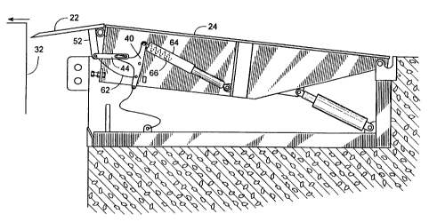
Once snubbing member 38 is taut, ramp 24 continuing to pivot upward
causes snubbing member 38 to pull main link 40 counter clockwise, as shown
in Figure 4. Main link 40 rotates about an axis 42 whose position is fixed
relative to ramp 24 by way of a conventional bracket. Such a bracket is well
known by those skilled in the art and is only schematically incorporated in
the
SUBSTITUTE SHEET (RULE 26)
CA 02380251 2002-01-25
WO 01/07716 PCT/US00/20283
illustration of axis 42 to more clearly show the operation of dock leveler 20.
Rotational motion of main link 40 drives a lip link 44 by way of a pin 46
engaging the end of a slot 48 of lip link 44. A second pin 50 couples lip link
44 to a lip lug 52 that rigidly extends from lip 22. Thus, lip 22 pivots (in
5 relation to ramp 24) about a hinge 54 in response to main link 40 rotating.
In one exemplary embodiment, main link 40, in conjunction with lip
link 44 provides a toggle-over-center mechanism 56 that latches lip 22 in an
extended position prior to ramp 24 descending. In Figure 3, mechanism 56 is
first shown in an unlatched configuration with pin 46 generally above a line
58
that is defined by axis 42 and pin 50. Then. as main link 40 rotates to the
position shown in Figure 4, pin 46 moves Generally below line 58 to place
mechanism 56 in an over-toggle, latched configuration. To avoid making it
too difficult to unlatch, a stop 60 is fixed relative to ramp 24 to prevent
mechanism 56 from over-traveling in its latched configuration.
Once latched, the over-toggle position of main link 40 and lip link 44
holds lip 22 in a latched mode where lip 22 is held substantially fixed
relative
to ramp 24, regardless of any tension in snubbing member 38. This ensures
that lip 22 remains extended over the back edge of the vehicle, as ramp 24
pivots downward, as shown in Figure 5. As ramp 22 descends farther, as
shown in Figure 6, the underside of lip 22 engages vehicle 32. For example,
lip 22 might rest upon the back end of a trailer bed of a truck.
Vehicle 32 abutting lip 22 may, in effect, rotate lip 22 slightly upward
relative to ramp 24. The relative rotational motion could cause a release link
62 (e.g., a slidable bar or a pliable elongated member, such as a chain or a
cable) to pull mechanism 56 into its unlatched configuration. In other words,
the force created at lip 22 engaging vehicle 32 is used for positively
unlatching
lip 22. This basic concept can be carried out by a variety of structures too
numerous to mention. However, as one example, release link 62 connects lip
lug 52 to main link 40, so as lip 22 pivots upward relative to ramp 24, the
resulting rotation of lug 52 pulls on link 62 to force main link 40 to rotate
clockwise about pin 42, thus moving main link 40 and lip link 44 to an under-
SUBSTITUTE SHEET (RULE 26)
CA 02380251 2002-01-25
WO 01/07716 PCT/US00/20283
6
toggle position. In this example, the action is facilitated by pin 46 being
free
to slide within slot 48. With dock leveler 20 in the position shown in Figure
6,
vehicle 32 may now be loaded or unloaded, if desired.
When vehicle 32 departs, as shown in Figure 7, lip 22 drops slightly, as
allowed by the travel of pin 46 within slot 48. This removes the tension in
release link 62 and allows lip 22 to descend while in an unlatched mode. Now
lip 22 and ramp 24 are both free to pivot downward to the position shown in
Figure 2 and eventually return to its standby position of Figure 1.
To prevent lip 22 from undergoing rapid descent, a dampener 64 can
be added to dampen the motion (i.e., reduce the velocity) of at least one of
lip
22, lip lug 52, lip link 44, or main link 40. For example, in one embodiment,
dampener 64 is a piston/cylinder arrangement with an integral spring 66
(Figure 7) that helps counteract the weight of lip 22. Spring 66 could be a
mechanical compression spring, or dampener 64 could be a gas spring
providing both functions of dampening motion and counteracting the weight
of lip 22. In one embodiment, dampener 64 is a fluid-filled piston/cylinder
such that compression of the cylinder results in fluid flow through a size-
controlled orifice to reduce the velocity of clockwise rotation of link 40.
Returning to Figure 5, where ramp 24 is descending with lip 22
latched, it is possible that lip 22 may miss vehicle 32. For example, vehicle
32
may be improperly parked or may not even be present at dock 26. In such a
case, vehicle 32 would not unlatch lip 22; thus ramp 24 and latched lip 22
could descend to a predetermined lower limit 70, as shown in Figures 8 and 9.
To address this situation, lip 22 is unlatclied by a mechanism other than the
vehicle.
For example, in one embodiment, a travel limiting member 68
obstructs continued downward movement of ramp 24 once ramp 24 reaches its
lower limit 70. In this example, member 68 is situated under ramp 24 to
engage mechanism 56 to forcible unlatch it automatically (i.e., without
additional intervention from a vehicle 32 or an operator). Obstructing member
68 engaging the underside of links 40 or 44 unlatches lip 22 by forcing main
SUBSTITLTTE SHEET (RULE 26)
CA 02380251 2002-01-25
WO 01/07716 PCT/US00/20283
7
link 40 to rotate clockwise, so mechanism 56 toggles through the center
position (toggle position) wherein pivots 50, 46 and 42 are collinear to an
under-toggle position wherein pivot 46 is alone a line connecting pivots 50
and 42 as shown in Figure 9. This unlatching operation is illustrated by dock
leveler 20 moving from the position shown in Figure 8 to that of Figure 9.
When lip 22 is unlatched by obstructing member 68, dock leveler 20
will eventually reach the position of Figure 10. From this extremely low
position, ramp 24 can be raised slightly and then re-lowered to its standby
position of Figure 1. This final operation might be carried out by an operator
manipulating some control or performed automatically in response to a limit
switch sensing that lip 22 or ramp 24 has reached some predetermined low
position with the lip in a pendant or near-pendant position.
Although the invention is described with respect to a preferred
embodiment, modifications thereto will be apparent to those skilled in the
art.
Therefore, the scope of the invention is to be determined by reference to the
claims that follow.
I claim:
SUBSTITUTE SHEET (RULE 26)