Note: Descriptions are shown in the official language in which they were submitted.
CA 02380485 2002-01-23
WO 01/08108 PCT/US00/20276
CURRENCY HANDLING SYSTEM EMPLOYING
AN INFRARED AUTHENTICATING SYSTEM
FIELD OF THE INVENTION
The present invention relates generallv to currency handling svstems such as
those
capable of distinguishing or discriminating between currencv bills of
different
denominations and/or authenticating currencv bills, more particularly, to such
svstems that
emplov infrared sensing svstems.
BACKGROUND OF THE INVENTION
Systems that are currently available for simultaneous scanning and counting of
documents such as paper currencv are relativelv complex and costly, and
relatively large
in size. The complexity of such systems can also lead to excessive service and
maintenance requirements. These drawbacks have inhibited more widespread use
of such
systems, particularly in banks and other financial institutions where space is
limited in
areas where the systems are most needed, such as teller areas. The above
drawbacks are
particularly difficult to overcome in systems which offer much-needed features
such as the
ability to authenticate the genuineness and/or determine the denomination of
the bills.
Therefore, there is a need for a small, compact system that can denominate
bills of
different denominations of bills. Likewise there is such a need for a system
that can
discriminate the denominations of bills from more than more country. Likewise
there is a
need for such a small compact system that can readilv be made to process the
bills from a
set of countries and yet has the flexibilitv so it can also be readily made to
process the bills
from a different set of one or more countries. Likewise, there is a need for a
currencv
handling system that can satisfy these needs while at the same time being
relativelv
inexpensive.
Counterfeit currency poses a problem for governments and private citizens. For
example, a bank or retailer that discovers it has accepted counterfeit
currency occurs a
loss for the amount of counterfeit currency it has accepted. Accordingly,
there is a need
for a device that can detect counterfeit currency. Furthermore, for
institutions which
process large quantities of currency, the need for a device that can
automatically detect
counterfeit currency is particularly great because the likelihood that such
institutions may
encounter and inadvertently accept counterfeit currency increases with the
volume of
currency processed. Furthermore, when large quantities of bills must be
processed, the
CA 02380485 2005-12-30
2
time which can be devoted to examine individual bills generall_y decreases.
While some
automatic counterfeit detection systems of been developed, the speed at which
these
systems can operate is linuted. Likewise, some counterfeit bills can not be
detected using
current counterfeit detection systems.
Accordingly, there is a need for a device which can automatically detect
counterfeit cu~rency. In particular there is a need for a device that can
automatically
detect counterfeit Mexican 50 peso currency. Likewise, there is a need for
such a device
that can operate at a high rate of speed such as on the order of 800 to 1500
bills per
minute.
SUMMARY OF THE INVENTION
A document handling system is configured for detecting counterfeit bills using
infrared light. The document handling system comprises an infrared light
source, a sensor
that is adapted to produce an output signal in response to infrared light
illumination of a
document, and a processor that is programmed to receive the signal and to
authenticate
the document based thereon.
According to an aspect of the present invention there is provided a currency
handling system for processing currency bills, comprising an input receptacle
adapted to
receive a stack of bills of a plurality of denominations to be processed, at
least one output
receptacle adapted to receive the bills after the bills have been processed, a
transport
mechanism adapted to transport the bills, one at a time, from the input
receptacle to the at
least one output receptacle, a denominating sensor disposed adjacent to the
transport
mechanism adapted to retrieve denominating characteristic information from
each of the
bills, an infrared light source disposed adjacent to the transport mechanism
adapted to
illuminate a surface of a bill with infrared light, a sensor disposed adjacent
to the
transport mechanism adapted to optically sample the bill in response to
infrared light
illumination along a dimension of the bill, the sensor being adapted to
produce a signal
indicative of samples obtained from the bill, a memory adapted to store a
plurality of
master authenticating threshold values corresponding to a plurality of
denominations and
master denominating information, and a processor adapted to receive the output
signal
from the sensor, the processor adapted to determine a difference sum value for
each of
the bills, the processor adapted to determine the denomination of each of the
bills by
comparing the retrieved denominating characteristic information to the master
CA 02380485 2005-12-30
2a
denominating information, the processor adapted to determine the authenticity
of each of
the bills by comparing the difference sum value to a master threshold value
corresponding to the determined denomination, and wherein the authenticity of
the bills
is assessed relative to being Mexican 50 Peso notes.
According to another aspect of the present invention there is provided a
currency
handling system for processing currency bills, comprising an input receptacle
adapted to
receive a stack of bills to be processed, at least one output receptacle
adapted to receive
the bills after the bills have been processed, a transport mechanism adapted
to transport
the bills, one at a time, from the input receptacle to the at least one output
receptacle, an
infrared light source disposed adjacent to the transport mechanism adapted to
illuminate a
surface of each of the bills with infrared light, a sensor disposed adjacent
to the transport
mechanism adapted to detect a pattern of light received from the surface of
each of the
bills in response to infrared light illumination along a dimension of each of
the bills, the
sensor adapted to produce a signal indicative of a pattern obtained from each
of the bills,
a memory adapted to store master authenticating patterns, and a processor
adapted to
receive the output signal from the sensor, the processor adapted to determine
the
authenticity of each of the bills by comparing the pattern obtained from each
of the bills
to master authenticating patterns, and wherein the authenticity of each of the
bills is
assessed relative to being Mexican 50 Peso notes.
According to a further aspect of the present invention there is provided a
method
for authenticating currency bills with a currency handling system, the method
comprising
receiving a stack of currency bills to be processed in an input receptacle,
transporting the
bills from the input receptacle, one at a time, past an evaluating unit to at
least one output
receptacle, illuminating a surface of each of the bills with infrared light as
each of the
bills are transported past the evaluating unit, sampling the optical
characteristics received
from a surface of a bill in response to illuminating the surface of the bill
with infrared
light as each of the bills are transported past the evaluating unit,
determining the
difference sum value for each of the bills, wherein at least one range of
samples obtained
from each of the bills is used to determine the difference sum value for each
of the bills,
wherein the step of determining the difference sum value scaling the samples
obtained
from each of the bills such that a maximum sample value is set at 1000,
averaging a first
range of samples, averaging a second range of samples, determining a first
sample
difference total by summing the difference between each of the samples in the
first range
CA 02380485 2005-12-30
2b
of samples and the first sample average, determining a second sample
difference total by
summing the difference between each of the samples in the second range of
samples and
the second sample average, and summing the first sample difference total and
the second
sample difference total, and comparing the determined difference sum value for
each of
the bills to a master difference sum value stored in a memory of the currency
handling
system, and producing a suspect document error signal based on a comparison of
the
determined difference sum value and the master difference sum value.
According to a further aspect of the present invention there is provided a
method
for authenticating currency bills with a currency handling system, the method
comprising
receiving a stack of currency bills to be processed in an input receptacle,
transporting the
bills from the input receptacle, one at a time, past an evaluating unit to at
least one output
receptacle, illuminating a surface of each of the bills with infrared light as
each of the
bills are transported past the evaluating unit, detecting a pattern of light
received from a
surface of each of the bills in response to illuminating the surface of each
of the bills with
infrared light as each of the bills are transported past the evaluating unit,
comparing the
detected pattern of light received from the surface of each of the bills to
master
authenticating patterns stored in a memory of the currency handling system,
and
producing a suspect document error signal based on a comparison of the
detected pattern
of light and the master authenticating patterns, wherein the authenticity of
each of the
bills is assessed relative to being Mexican 50 Peso notes.
According to a further aspect of the present invention there is provided a
currency
handling system for processing currency notes, comprising an input receptacle
adapted to
receive a stack of currency notes to be processed, the stack of currency notes
including
Mexican 50 Peso notes, at least one output receptacle adapted to receive the
notes after
the notes have been processed, a transport mechanism adapted to transport the
notes, one
at a time, from the input receptacle to the at least one output receptacle, a
first sensor
disposed adjacent to the transport mechanism adapted to retrieve information
from each
of the notes including denominating characteristic information and face
orientation
information for each of the notes, an infrared light source disposed adjacent
to the
transport mechanism adapted to illuminate a surface of each of the notes with
infrared
light having a wavelength between 850 nanometers and 950 nanometers, a second
sensor
disposed adjacent to the transport mechanism adapted to optically sample the
infrared
light reflected off of the surface of each of the notes in response to
infrared light
CA 02380485 2005-12-30
2c
illumination of the surface of each of the notes along a dimension of each of
the notes,
the sensor adapted to produce a signal indicative of samples obtained from
each of the
notes, a memory adapted to store master authenticating threshold values
corresponding to
a plurality of face orientations of genuine Mexican 50 Peso notes and master
denominating characteristic information, and a processor adapted to determine
the
denomination of each of the notes, the processor adapted to determine the face
orientation of each of the notes which are Mexican 50 Peso notes, the
processor adapted
to determine a difference sum value for each of the Mexican 50 Peso notes, the
processor
adapted to determine the authenticity of each of the Mexican 50 Peso notes by
comparing
the determined difference sum value to a master authenticating threshold value
corresponding to the determined face orientation of the Mexican 50 Peso note.
According to a further aspect of the present invention there is provided a
method
for authenticating currency notes with a currency handling system, the method
comprising receiving a stack of currency notes to be processed in an input
receptacle, the
stack of currency notes including Mexican 50 Peso notes, transporting the
notes from the
input receptacle, one at a time, past an evaluating unit to at least one
output receptacle,
determining the denomination of each of the notes, determining the face
orientation of
each of the notes which are determined to be Mexican 50 Peso notes,
illuminating a
surface of each of the notes which are determined to be Mexican 50 Peso notes
with
infrared light as each of the notes are transported past the evaluating unit,
the infrared
light having a wavelength of 875 nanometers, sampling the infrared light
reflected off of
the surface of each of the notes in response to illuminating the surface of
each of the
notes with infrared light along a dimension of each of the notes as each of
the notes is
transported past the evaluating unit, determining a difference sum value for
each of the
notes determined to be Mexican 50 Peso notes, wherein the first twelve samples
and the
last twelve samples are used to determine the difference sum value for each of
the notes,
comparing the difference sum value for each of the notes determined to be
Mexican 50
Peso notes to a master difference sum value corresponding to the determined
face
orientation stored in a memory of the currency handling system, and producing
a suspect
document error signal based on a comparison of the determined difference value
and the
master difference sum value.
According to a further aspect of the present invention there is provided a
method
for assessing the authenticity of a currency note relative to being a genuine
Mexican 50
CA 02380485 2005-12-30
2d
Peso note with a currency note validator, the method comprising illuminating a
surface
of the note with an infrared light, sampling the optical characteristics
received from the
surface of the note in response to illuminating the surface of the note with
infrared light
along a dimension of the note, determining the difference sum value for the
note, wherein
at least one range of samples obtained from the note is used to determine the
difference
sum value, comparing the determined difference sum value to a master
authenticating
difference sum value stored in a memory of the currency note validator, and
producing a
suspect document error signal based on a comparison of the determined
difference value
sum and the master authenticating difference sum value.
According to a further aspect of the present invention there is provided a
method
for assessing the authenticity of a currency note relative to being a genuine
Mexican 50
Peso note with a currency note validator, the method comprising illuminating a
surface of
the note with an infrared light, sampling the optical characteristics received
from the
surface of the note in response to illuminating the surface of the note with
infrared light
along a dimension of the note, determining at least one difference total for
the note,
comparing the at least one determined difference total to a master
authenticating
difference total stored in a memory of the currency note validator, and
producing a
suspect document error signal based on a comparison of the at least one
determined
difference total and the master authenticating difference total.
According to a further aspect of the present invention there is provided a
currency
handling system for processing currency notes, comprising an input receptacle
adapted to
receive a stack of currency notes to be processed, the stack of currency notes
including
Mexican 50 Peso notes, at least one output receptacle adapted to receive the
notes after
the notes have been processed, a transport mechanism adapted to transport the
notes, one
at a time, from the input receptacle to the at least one output receptacle, an
infrared light
source disposed adjacent to the transport mechanism adapted to illuminate a
surface of
each of the notes with infrared light, a visible light source disposed
adjacent to the
transport mechanism adapted to illuminate the surface of each of the notes
with visible
light, a sensor responsive to infrared light disposed adjacent the transport
path adapted to
optically sample infrared light reflected off of the surface of each of the
notes in response
to infrared illumination of the surface of the note, a sensor responsive to
visible light
disposed adjacent the transport path adapted to optically sample the visible
light reflected
off of the surface of each of the notes in response to visible-light
illumination of the
CA 02380485 2005-12-30
2e
surface of the note, a memory adapted to store a plurality of threshold values
corresponding to a plurality of authentication sensitivities, and a processor
adapted to
determine the denomination of each of the notes, the processor being adapted
to
determine a correlation value between the visible light reflectance samples
and the
infrared light reflectance samples obtained from each note determined to be a
Mexican
50 peso note, the processor being adapted to authenticate each of notes
determined to be
Mexican 50 Peso notes by comparing the determined correlation value to a
threshold
value stored in the memory, the processor being adapted to generate a suspect
document
error signal based on a comparison of the determined correlation value and the
stored
threshold value.
According to a further aspect of the present invention there is provided a
currency
handling system for processing currency notes, comprising an input receptacle
adapted to
receive a stack of currency notes to be processed, at least one output
receptacle adapted
to receive the notes after the notes have been processed, a transport
mechanism adapted
to transport each of the notes, one at a time, from the input receptacle to
the at least one
output receptacle, an infrared light source disposed adjacent to the transport
mechanism
adapted to illuminate a surface of each of the notes with infrared light, a
visible light
source disposed adjacent to the transport mechanism adapted to illuminate the
surface of
each of the notes with visible light, at least one sensor disposed adjacent to
the transport
mechanism, the at least one sensor adapted to optically sample infrared light
reflected off
of the surface of each of the notes in response to infrared light illumination
of the surface
of each of the notes, the at least one sensor adapted to optically sample the
visible light
reflected off of the surface of each of the notes in response to visible light
illumination of
the surface of each of the notes, a memory adapted to store at least one
correlation
threshold value, and a processor adapted to determine a correlation value
between the
visible light reflectance samples and the infrared light reflectance samples
obtained from
each of the notes, the processor being adapted to authenticate each of notes
by comparing
the determined correlation value to the at least one correlation threshold
value stored in
the memory, the processor being adapted to generate a suspect document error
signal
based on a comparison of the determined correlation value and the stored at
least one
correlation threshold value.
CA 02380485 2005-12-30
2f
According to a further aspect of the present invention there is provided a
method
for authenticating currency notes with a currency handling system, the method
comprising receiving a stack of currency notes to be processed in an input
receptacle, the
stack of currency notes including Mexican 50 Peso notes, transporting the
notes from the
input receptacle, one at a time, past an evaluating unit to at least one
output receptacle,
determining the denomination of each of the notes, illuminating a surface of
each of the
notes which are determined to be Mexican 50 Peso notes with infrared light as
each of
the notes are transported past the evaluating unit, illuminating a surface of
each of the
notes which are determined to be Mexican 50 Peso notes with visible light as
each of the
notes are transported past the evaluating unit, sampling the infrared light
reflected off of
the surface of each of the notes in response to illuminating the surface of
each of the
notes with infrared light as each of the notes are transported past the
evaluating unit,
sampling the visible light reflected off of the surface of each of the notes
in response to
illuminating the surface of each of the notes with visible light as each of
the notes are
transported past the evaluating unit, determining a correlation value between
the visible
light reflectance samples and the infrared light reflectance samples for each
of the notes,
comparing the determined correlation value for each of the notes to a master
threshold
value stored in a memory of the currency handling system, and producing a
suspect
document error signal when the determined difference total for each of the
notes is not
less than the master threshold value.
According to a further aspect of the present invention there is provided a
method
for authenticating currency notes with a currency handling system, the method
comprising receiving a stack of currency notes to be processed in an input
receptacle,
transporting the notes from the input receptacle, one at a time, past an
evaluating unit to
at least one output receptacle, illuminating a surface of each of the notes
with infrared
light as each of the notes are transported past the evaluating unit,
illuminating a surface
of each of the notes with visible light as each of the notes are transported
past the
evaluating unit, sampling the infrared light reflected off of the surface of
each of the
notes in response to illuminating the surface of each of the notes with
infrared light as
each of the notes are transported past the evaluating unit, sampling the
visible light
reflected off of the surface of each of the notes in response to illuminating
the surface of
each of the notes with visible light as each of the notes are transported past
the evaluating
unit, determining a correlation value between the visible light reflectance
samples and the
CA 02380485 2005-12-30
2g
infrared light reflectance samples for each of the notes, and comparing the
determined
correlation value for each of the notes to a threshold value stored in a
memory of the
currency handling system.
The above sununary of the present invention is not intended to represent each
embodiment, or every aspect, of the present invention. Additional features and
benefits of
the present invention will become apparent from the detailed description,
figures, and
claims set forth below_
BRIEF DESCRIPTION OF THE DRAWINGS
FIG. I is a functional block diaaram of a currency handling svstem embodving
the
present invention;
FIG_ 2a is a perspective view of a single pocket currencv handling s_vstem
according to one embodiment of the present invention;
FIG. 2b is a sectional side view of the sinele pocket currency handling system
of
FIG_ 2a depicting various transport rolls in side elevation,
FIG. 2c is a top plan view of the interior mechanism of the svstem of FIG. 2a
for
transporting bills across a scanhead, and also showing the stacking wheels at
the front of
the system;
FIG_ 2d is a sectional top view of the interior mechanism of the svstem of
FIG. 2a
for transporting bills across a scanhead, and also showing the stacking wheels
at the front
of the svstem;
WO 01/08108 CA 02380485 2002-01-23 pCT/US00/20276
FIG. 3a is a perspective view of a two-pocket currency handling system
according
to one embodiment of the present invention;
FIG. 3b is a sectional side view of the two-pocket currency handling system of
FIG. 3a depicting various transport rolls in side elevation;
FIG. 4a is an enlarged sectional side view depicting the scanning region
according
to one embodiment of the present invention;
FIG. 4b is a sectional side view depicting the scanheads according to one
embodiment of the present invention;
FIG. 4c is a front view depicting the scanheads of FIG. 5b according to one
embodiment of the present invention;
FIG. 5 is a functional block diagram of a standard optical scanhead;
FIG. 6 is a functional block diagram of a full color scanhead;
FIG. 7a is a perspective view of a U. S. currency bill and an area to be
optically
scanned on the bill;
FIG. 7b is a diagrammatic perspective illustration of the successive areas
scanned
during the traversing movement of a single bill across an optical scanhead
according to
one embodiment of the present invention;
FIG. 7c is a diagrammatic side elevation view of the scan area to be optically
scanned on a bill according to one embodiment of the present invention;
FIG. 7d is a top plan view of a bill indicating a pluralitv areas to be
optically
scanned on the bill;
FIG. 8a is a perspective view of a bill and a plurality areas to be color
scanned on
the bill;
FIG. 8b is a diagrammatic perspective illustration of the successive areas
scanned
during the traversing movement of a single bill across a color scanhead
according to one
embodiment of the present invention;
FIG. 8c is a diagrammatic side elevation view of the scan area to be color
scanned
on a bill according to one embodiment of the present invention;
FIG. 9 is a timing diagram illustrating the operation of the sensors sampling
data
according to an embodiment of the present invention;
FIG. l0a-10e are graphs of color information obtained by a color scanhead;
FIG. 11 is a functional block diagram of a magnetic scanhead;
CA 02380485 2004-09-17
4
FIGS. 12a-12d are a flow chart of how the system operates in standard bill
evaluation mode;
FIG. 13 is a flowchart of an authenticating technique according to one
embodiment of the present invention;
FIG. 14 is a flowchart of an authenticating technique according to one
embodiment of the present invention; and
FIG. 15 is a flow chart of an authenticating technique according to another
embodiment of the present invention.
While the invention is susceptible to various modifications and alternative
forms,
specific embodiments thereof have been shown by way of example in the drawings
and
will herein be described in detail. It should be understood, however, that it
is not
intended to limit the.invention to the particular forms disclosed, but on the
contrary, the
intention is to cover allmodifications, equivalents, and alternatives falling
within the
spirit and scope of the invention as defined by the appended claims.
DETAILED DESCRIPTION OF THE EMBODIMENTS
FIG. 1 illustrates in functional block diagram form the operation of currency
handling systems according to the present invention. FIGS. 2a-2d and 3a-3b
then
illustrate various physical. embodiments of currency handling systems that
function as
discussed in connection with FIG. 1 and that employ a color scanning
arrangement as
described in PCT publication No. WO 99/48042 entitled "Color Scanhead and
Currency
Handling System Employing the Same." These embodiments will be described first
and
then the details concerning embodiments of employing infrared light and
processing will
be described.
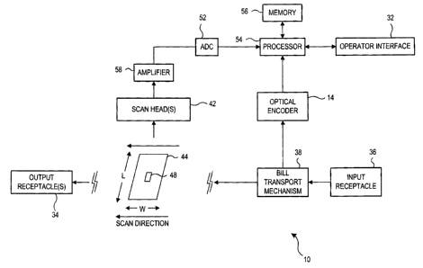
Turning to FIG. 1, a currency handling system 10 comprises an input receptacle
36 for receiving a stack of currency bills to be processed. The processing may
include
evaluating, denominating, authenticating, and/or counting the currency bills.
In addition
to handling currency bills, the currency handling system 10 may be designed to
accept
and process other documents including but not limited to stamps, stock
certificates,
coupons, tickets, checks and other identifiable documents.
Bills placed in the input receptacle are transported one by one by a transport
mechanism 38 along a transport path past one or more scanheads or sensors 42.
The
WO 01/08108 CA 02380485 2002-01-23
PCT/US00/20276
scanhead(s) 42 may perform magnetic, optical and other types of sensing to
generate
signals that correspond to characteristic information received from a bill 44.
In
embodiments to be described below, the scanhead(s) 42 comprises a color
scanhead. In
the embodiment shown in FIG. 1, the scanhead(s) 42 employs a substantially
rectangular
5 shaped sample region 48 to scan a segment of each passing currency bill 44.
After
passing the scanhead(s) 42, each of the bills 44 is transported to one or more
output
receptacles 34 which may include stacking mechanisms to re-stack the bills 44.
According to some embodiments the scanhead(s) 42 generates analog output(s)
which are amplified by an amplifier 58 and converted into a digital signal by
means of an
analog-to-digital converter (ADC) unit 52 whose output is fed as a digital
input to a
controller or processor such as a central processing unit (CPU), a processor
or the like.
The process (such as a microprocessor) controls the overall operation of the
currency
handling system 10. An encoder 14 linked to the bill transport mechanism 38
provides
input to the processor 54 to determine the timing of the operations of the
currency
handling system 10. In this manner, the CPU is able to monitor the precise
location of
bills as they are transported through the currency handling system.
The processor 54 is also operatively coupled to a memory 56. The memory
comprises one or more types of memories such as a random access memory
("RAM"), a
read only memory ("ROM"), EPROM or flash memory depending on the information
stored or to be stored therein. The memory 56 stores software codes and/or
data related
to the operation of the currency handling system 10 and information for
denominating
and/or authenticating bills.
An operator interface panel and display 32 provides an operator the capability
of
sending input data to, or receiving output data from, the currency handling
system 10.
Input data may comprise, for example, user-selected operating modes and user-
defined
operating parameters for the currency handling system 10. Output data may
comprise, for
example, a display of the operating modes and/or status of the currency
handling system
10 and the number or cumulative value of evaluated bills. In one embodiment,
the
operator interface panel 32 comprises a touch-screen "keypad" and display
which may be
used to provide input data and display output data related to operation of the
currency
handling system 10. Alternatively, the operator interface 3 2 may employ
physical keys or
CA 02380485 2004-09-17
6
buttons and a separate display or a combination of physical keys and displayed
touch-
screen keys.
A determination of authenticity or denomination of a bill under test is based
on a
comparison of scanned data associated with the test bill to the corresponding
master data
stored in the memory 56. For example, where the currency handling system 10
comprises
a denomination discriminator, a stack of bills having undetermined
denominations may be
processed and the denomination of each bill in the stack determined by
comparing data
generated from each bill to prestored master information. If the data from the
bill under
test sufficiently matches master information associated with a particular
denomination and
bill-type stored in memory -a determination of denomination may be made.
The master information may comprise numerical data associated with various
denominations of currency bills. The numerical data may comprise, for example,
thresholds of acceptability to be used in evaluating test bills, based on
expected
numerical values associated with the currency or a range of numerical values
defining
upper and lower limits of acceptability. The thresholds may be associated with
various
sensitivity levels. The master information may also comprise pattern
information
associated with the currency such as, for example, optical or magnetic
patterns.
Turning to FIGS. 2a-2d, FIG. 2a is a perspective view of a currency handling
system 10 having a single output receptacle 117 according to one embodiment of
the
present invention. FIG. 2b is a sectional side view of the single pocket
currency handling
system of FIG. 2a depicting various transport rolls in side elevation and FIG.
2c is a top
plan view of the interior mechanism of the system of FIG. 2a for transporting
bills across
a scanhead, and also showing the stacking wheels 112, 113 at the front of the
system.
The mechanics of this embodiment will be described briefly below. For more
detail,
single pocket currency'handling systems are described in greater detail in
U.S. Patent No.
5,687,963 entitled "Method and Apparatus for Discriminating and Counting
Documents,"
and U.S. Patent No. 5,295,196 entitled "Method and Apparatus for Currency
Discriminating and Counting," both of which are assigned to the assignee of
the present
invention. The physical embodiment of the currency handling system described
in U.S.
Patent No. 5,687,963 including the transport mechanism and its operation is
similar to
that depicted in FIGS. 2a-2d except for the scanhead arrangement. The currency
handling
system of FIGS. 2a-2d employs a
x I h 1
CA 02380485 2004-09-17
7
color scanhead 300 according to the present invention or in addition to one of
the
standard scanheads 70 described in U.S. Patent No. 5,687,963. The currency
handling
system of FIGS. 2a-2d is designed to transport and process bills at a rate in
excess of 800
bills per minute, preferably in excess of 1200 bills per minute.
In the single-pocket system 10, the currency bills are fed, one by one, from a
stack
of currency bills placed in the input receptacle 36 -into a transport
mechanism, which.
guides the currency bills past sensors to a single output receptacle 117. The
single-
pocket currency handling system 10 includes a hoitsing 100 having a ri gid
frame formed
by a pair of side plates 101 and 102, top plate 103a, and a lower front plate
104. The
currency handling system 10 also has an operator interface 32a. As shown in
FIG. 2a the
operator interface panel comprises a LCD display and physical keys or buttons.
Alternatively or additionally, the operator interface panel may comprise a
touch screen
such as a full graphics display.
The input receptacle 36 for receiving a stack of bills to be processed is
formed by
downwardly sloping and converging walls 105 and 106 formed by a pair of
removable
covers 107 and 108. The rear wall 106 supports a removable hopper (extension)
109
which includes a pair of vertically disposed side walls 110a and 110b which
complete the
receptacle for the stack of currency bills to be processed.
From the input receptacle, the currency bills are moved in seriatim from the
bottom of the stack along a curved guideway 111 which receives bills moving
downwardly and rearwardly and changes the direction of travel to a forward
direction.
The curvature of the guideway 111 corresponds substantially to the curved
periphery of a
drive roll 123 so as to form a narrow passageway for the bills along the rear
side of the
drive roll. The exit end of the guideway 111 directs the bills onto a linear
path where the
bills are scanned and stacked. The bills are transported and stacked with the
narrow
dimension of the bills maintained parallel to the transport path and the
direction of
movement at all times.
Stacking of the bills is effected at the forward end of the linear path, where
the
bills are fed into a pair of driven stacking wheels 112 and 113. These wheels
project
upwardly through a pair of openings in a stacker plate 114 to receive the
bills as they are
advanced across the downwardly sloping upper surface of the plate. The stacker
wheels
112 and 113 are supported for rotational movement about a shaft 115 journalled
on the
. .,
CA 02380485 2004-09-17
8
rigid frame and driven by a.motor 116. The flexible blades of the stacker
wheels deliver
the bills into the output receptacle 117 at the forward end of the stacker
plate 114.
During operation, a currency bill which is delivered to the stacker plate 114
is picked up
by the flexible blades and becomes lodged between a pair of adjacent blades
which, in
combination, define a curved enclosure which decelerates a bill entering
therein and
serves as a means for supporting and transferring the bill into the output
receptacle 117
as the stacker wheels 112, 113 rotate. The mechanical configuration of the
stacker
wheels, as well as the manner in which they cooperate with the stacker plate,
is
conventional and, accordingly, is not described in detail herein.
Returning now to the input region of the system as shown in FIGS. 2a-2d and 4a-
b, bills that are stacked on the bottom wall 105 of the input receptacle are
stripped, one at
a time, from the bottom of the stack.. The bills are stripped by a pair of
stripping wheels
120 mounted on a drive shaft 121 which, in turn, is supported across the side
walls 101,
102. The stripping wheels 120 project through a pair of slots formed in the
cover 107.
Part of the periphery of each wheel 120 is provided with a raised high-
friction, serrated
surface 122 which engages the bottom bill of the input stack as the wheels 120
rotate, to
initiate feeding movement of the bottom bill from the stack.. The serrated
surfaces 122
project radially beyond the rest of each wheel's periphery so that the wheels
"jog" the bill
stack during each revolution so as to agitate and loosen the bottom currency
bill within
the stack, thereby facilitating the stripping of the bottom bill from the
stack.
The stripping wheels 120 feed each stripped bill onto a drive roll 123 mounted
on
a driven shaft 124 supported across the side walls 101 and 102. The drive roll
123
includes a central smooth friction surface 125 formed of a material such as
rubber or hard
plastic. This smooth friction surface 125 is sandwiched between a pair of
grooved
surfaces 126 and 127 having serrated portions 128 and 129 formed from a high-
friction
material. This feed and drive arrangement is described in detail in U.S.
Patent No.
5,687,963.
In order to ensure firm engagement between the drive roll 123 and the currency
bill
being fed, an idler roll 130 urges each incoming bill against the smooth
central surface 125
of the drive roll 123. The idler roll 130 is joumalled on a pair of arms which
are pivotally
mounted on a support shaft 132. Also mounted on the shaft 132, on opposite
sides of'the
idler roll 130, are a pair of grooved guide wheels 133 and 134. The grooves
WO 01/08108 CA 02380485 2002-01-23 pCT/US00/20276
9
in these two wheels 133, 134 are registered with the central ribs in the two
grooved
surfaces 126, 127 of the drive roll 123. The wheels 133, 134 are locked to the
shaft 132,
which in turn is locked against movement in the direction of the bill movement
(clockwise
for roll 123, counterclockwise for wheels 133, 134, as viewed in FIG. 2b) by a
one-way
spring clutch (not shown). Each time a bill is fed into the nip between the
guide wheels
133, 134 and the drive roll 123, the clutch is energized to turn the shaft 132
just a few
degrees in a direction opposite the direction of bill movement. These repeated
incremental movements distribute the wear uniformly around the circumferences
of the
guide wheels 133, 134. Although the idler roll 130 and the guide wheels 133,
134 are
mounted behind the guideway 111, the guideway is apertured to allow the roll
130 and
the wheels 133, 134 to engage the bills on the front side of the guideway.
Beneath the idler roll 130, a spring-loaded pressure roll 136 (FIG. 2b)
presses the
bills into firm engagement with the smooth friction surface 125 of the drive
roll as the bills
curve downwardly along the guideway 111. This pressure roll 136 is journalled
on a pair
of arms 137 pivoted on a stationary shaft 138. A spring 139 attached to the
lower ends of
the arms 137 urges the roll 136 against the drive roll 133, through an
aperture in the
curved guideway 111.
At the lower end of the curved guidewav 111, the bill being transported bv the
drive roll 123 engages a flat transport or guide plate 140. Currency bills are
positively
driven along the flat plate 140 by means of a transport roll arrangement which
includes
the drive roll 123 at one end of the plate and a smaller driven roll 141 at
the other end of
the plate. Both the driver roll 123 and the smaller roll 141 include pairs of
smooth raised
cylindrical surfaces 142 and 143 which hold the bill flat against the plate
140. A pair of
0-rings fit into grooves 144 and 145 formed in both the roll 141 and the roll
123 to
engage the bill continuously between the two rolls 123 and 141 to transport
the bill while
helping to hold the bill flat against the transport plate 140.
The flat transport or guide plate 140 is provided with openings through which
the
raised surfaces 142 and 143 of both the drive roll 123 and the smaller driven
roll 141 are
subjected to counter-rotating contact with corresponding pairs of passive
transport rolls
150 and 151 having high-friction rubber surfaces. The passive rolls 150, 151
are mounted
on the underside of the flat plate 140 in such a manner as to be freewheeling
about their
axes and biased into counter-rotating contact with the corresponding upper
rolls 123 and
CA 02380485 2004-09-17
141. The passive rolls 150 and 151 are biased into contact with the driven
rolls 123 and
141 by means of a pair of H-shaped leaf springs (not shown). Each of the four
rolls 150,
151 is cradled between_a pair of parallel arms of one of the H-shaped leaf
springs. The
central portion of each leaf spring is fastened to the plate 140, which is
fastened rigidly to
5 the frame of the system, so that the relatively stiff arms of the H-shaped
springs exert a
constant biasing pressure against the rolls and push them against the upper
rolls 123 and
141.
The points of contact between the driven and passive transport rolls are
preferably
coplanar with the flat upper surface of the plate 140 so that currency bills
can be
10 positively driven along the top surface of the plate in a flat manner. The
distance
between the axes of the two driven transport rolls, and the corresponding
counter-rotating
passive rolls, is selected to be just short of the length of the narrow
dimension of the
currency bills. Accordingly, the bills are firmly gripped under uniform
pressure between
the upper and lower transport rolls within the scanhead area, thereby
minimizing the
possibility of bill skew and enhancing the reliability of the overall scanning
and
recognition process.
The positive guiding arrangement described above is advantageous in that
uniform guiding pressure, is maintained on the bills as they are transported
through the
sensor or scanhead area, and twisting or skewing of the bills is substantially
reduced.
This positive action is supplemented by the use of the H-springs for uniformly
biasing
the passive rollers into contact with the active rollers so that bill twisting
or skew
resulting from differential pressure applied to the bills along the transport
path is
avoided. The 0-rings function as simple, yet extremely effective means for
ensuring that
the central portions of the bills are held flat.
As shown in FIG. 2c, the optical encoder 32 is mounted on the shaft of the
roller
141 for precisely tracking the position of each bill as it is transported
through the system,
as discussed in detail below in connection with the optical sensing and
correlation
technique. The encoder 32 also allows the system to be stopped in response to
an error
occurring or the detection of a "no call" bill. A system employing an encoder
to
accurately stop a scanning system is described in detail in U.S. Patent No.
5,687,963.
The single pocket currency system 10 described above in connection with FIGS.
2a-2d, is small and compact, such that it may be rested upon a tabletop or
countertop.
WO 01/08108 CA 02380485 2002-01-23 pCT/US00/20276
11
According to one embodiment, the single-pocket currency handling system 10 has
a small
size housing 100. The small size housing 100 provides a currency handling
system 10 that
occupies a small area or "footprint." The footprint is the area that the
system 10 occupies
on the table top and is calculated by multiplying the width (W 1) and the
depth (D 1).
Because the housing 100 is compact, the currency handling system 10 may be
readily used
at any desk, work station or teller station. Additionally, the small size
housing 100 is light
weight allowing the operator to move it between different work stations.
According to
one embodiment the currency handling system 10 has a height (H 1) of about
9'/z inches
(24.13 cm), width (W 1) of about 11 inches (27.94 cm), and a depth (D 1) of
about 12
inches (30.48 cm) and weighs approximately 15-20 pounds. In this embodiment,
therefore, the currency handling system 10 has a "footprint" of about 11
inches by 12
inches (27.94 cm by 30.48 cm) or approximately 132 square inches (851.61 cm'')
which is
less than one square foot, and a volume of approximately 1254 cubic inches
(20,549.4
cm) which is less than one cubic foot. Accordingly, the system is sufficiently
small to fit
on a typical tabletop. The system is able to accommodate various currency,
including
German currency which is quite long in the X dimension (compared to U.S.
currency).
The width of the system is therefore sufficient to accommodate a German bill
which is
about 7.087 inches (180 mm) long. Such a system is able to accommodate Mexican
currency. The system can be adapted for longer currencv by making the
transport path
wider, which can make the overall system wider.
One of the contributing factors to the footprint size of the currency handling
system 10 is the size of the currency bills to be handled. For example, in the
embodiment
described above, the width is less than about twice the length of a U.S.
currency bill and
the depth is less than about 5 times the width of a U.S. currency bill. Other
embodiments
of the single pocket currency handling system 10 have a height (H1) ranging
from 7
inches to 12 inches, a width (W 1) ranging from 8 inches to 15 inches, and a
depth (D 1)
ranging from 10 inches to 15 inches and a weight ranging from about 10-30
pounds.
As best seen in FIG. 2b, the currency handling system 10 has a relatively
short
transport path between the input receptacle and the output receptacle. The
transport path
beginning at point TB 1(where the idler roll 130 engages the drive roll 123 )
and ending at
point TE1 (where the second driven transport roll 141 and the passive roll 151
contact)
has an overall length of about 41/2 inches. The distance from point TM1 (where
the
CA 02380485 2002-01-23
WO 01/08108 PCTIUSOO/20276
12
passive transport roll 150 engages the drive roll 123) to point TE 1(where the
second
driven transport roll 141 and the passive roll 151 contact) is somewhat less
than 21/2
inches, that is, less than the width of a U.S. bill. Thus, The distance from
point TB 1
(where the idler roll 130 engages the drive roll 123) to point TM1 (where the
passive
transport roll 150 engages the drive roll 123) is about 2 inches.
Turning to FIGS. 3a and 3b, FIG. 3a is a perspective view of a two-pocket
currency handling system 20 according to one embodiment of the present
invention and
FIG. 3b is a sectional side view of the two-pocket currency handling system of
FIG. 3a
depicting various transport rolls in side elevation. In other emodiments of
the currency
handling system, the currency handling system can have more than two pockets
such as,
for example, three, four, five, or six pockets. Multi-pocket embodiments of
the currency
handling system are described in detail in commonly owned Published PCT
Application
Nos. WO 97/45810 and WO 99/48042.
As with the single pocket currency system 10 described above in connection
with
FIGS. 2a-2d, the multi-pocket currency handling system 20 shown in FIGS. 3a-3b
are
small and compact, such that they may be rested upon a tabletop. According to
one
embodiment, the two pocket currency handling system 20 enclosed within a
housing 200
has a small footprint that may be readily used at any desk, work station or
teller station.
Additionally, the currency handling system is light weight allowing it to be
moved
between different work stations. According to one embodiment, the two-pocket
currency
handling system 20 has a height (H2) of about 18 inches. width (W2) of about
131/
inches, and a depth (D2) of about 171/4 inches and weighs approximately 42
pounds.
Accordingly, the currency handling system 20 has a footprint of about 131h
inches by
about 17 inches or approximately 230 square inches or about 11/2 square feet
and a
volume of about 4190 cubic inches or slightly more than 21/; cubic feet, which
is
sufficiently small to conveniently fit on a typical tabletop. One of the
contributing factors
to the footprint size of the currency handling system 20 is the size of the
currency bills to
be handled. For example in the embodiment described above the width is
approximatelv
21/4 times the length of a U.S. currency bill and the depth is approximately 7
times the
width of a U.S. currency bill.
According to another embodiment, the two-pocket currency handling system 20
has a height (H2) ranging from 15-20 inches, a width (W2) ranging from 10-15
inches,
CA 02380485 2004-09-17
13
and a depth (D2) ranging from 15-20 inches and a weight ranging from about 35-
50
pounds. The currency handling system 10 has a footprint ranging from 10-15
inches by
15-20 inches or approximately 150-300 square inches and a volume of about 2250-
6000
cubic inches, which is sufficiently small to conveniently fit on a typical
tabletop.
According to another embodiment, the small size housing 200 may have a
height (H2) of about 20 inches or less, width (W2) of about 20 inches or less,
and a depth
(D2) of about 20 inches or less and weighs approximately 50 pounds or less. As
best
seen in FIG. 3b, the currency handling system 20 has a short transport path
between the
input receptacle and the output receptacle. The transport path has a length of
about 10'/2
inches between the beginning of the transport path at point TB2 (where the
idler roll 230
engages the drive roll 223) and the tip of the diverter 260 at point TM1 and
has an overall
length of about 15'/z inches from point TB2 to point TE2 (where the rolls 286
and 282
contact).
Referring now to FIGS. 3a and 3b, parts and components similar to those in the
embodiment of FIGS. 2a-2d are designated by similar reference numerals. For
example,
parts designated by 100 series reference numerals in FIGS. 2a-2d are
designated by similar
200 series reference numerals in FIGS. 3a and 3b, while parts which we
duplicated one or
more times, are designated by like reference numerals with suffixes a, b, c,
etc. The
mechanical portions of the multi-pocket currency handling systems include a
housing 200
having the input receptacle 36 for receiving a stack of bills to be processed.
The
receptacle 36 is formed by downwardly sloping and converging walls 205 and 206
(see
FIG. 3b) formed by a pair. of removable covers (not shown) which snap onto a
frame. The
converging wall 206 supports a removable hopper (not shown) that includes
vertically
disposed side walls (not shown). One embodiment of an input receptacle was
described
and illustrated in detail above and applies to the multi-pocket currency
handling systems
10. The multi-pocket currency handling systems 10 also include an operator
interface 32b
as described for the single pocket currency handling device 10.
From the input receptacle 36, the currency bills in each of the multi-pocket
systems (FIGS. 3a-3b) are moved in seriatim from the bottom of a stack of
bills along a
curved guideway 211, which receives bills moving downwardly and rearwardly and
changes the direction of travel to a forward direction. The curvature of the
guideway 211
corresponds substantially to the curved periphery of a drive roll 223 so as to
fonn a
CA 02380485 2002-01-23
WO 01/08108 PCTIUSOO/20276
14
narrow passageway for the bills along the rear side of the drive roll 223. An
exit end of
the curved guidewav 211 directs the bills onto the transport plate 240 which
carries the
bills through an evaluation section and to one of the output receptacles 34.
In the two-pocket embodiment (FIG. 3b), for example, stacking of the bills is
accomplished by a pair of driven stacking wheels 35 a and 37a for the first or
upper output
receptacle 34a and bv a pair of stacking wheels 35b and 37b for the second or
bottom
output receptacle 34b. The stacker wheels 35a, 37a and 35b, 37b are supported
for
rotational movement about respective shafts 215a, b journalled on a rigid
frame and
driven by a motor (not shown). Flexible blades of the stacker wheels 35a and
37a deliver
the bills onto a forward end of a stacker plate 214a. Similarly, the flexible
blades of the
stacker wheels 35b and 37b deliver the bills onto a forward end of a stacker
plate 214b.
A diverter 260 directs the bills to either the first or second output
receptacle 34a, 34b.
When the diverter is in a lower position, bills are directed to the first
output receptacle
34a. When the diverter 260 is in an upper position, bills proceed in the
direction of the
second output receptacle 34b.
The two-pocket document evaluation devices in FIGS. 3a and 3b have a transport
mechanism which includes a series of transport plates or guide plates 240 for
guiding
currency bills to one of a plurality of output receptacles 34. The transport
plates 240
according to one embodiment are substantially flat and linear without any
protruding
features. Before reaching the output receptacles 34, a bill is moved past the
sensors or
scanhead 20 to be, for example, evaluated, analyzed, authenticated,
discriminated,
counted and/or otherwise processed.
The two-pocket document evaluation devices move the currency bills in seriatim
from the bottom of a stack of bills along the curved guideway 211 which
receives bills
moving downwardly and rearwardly and changes the direction of travel to a
forward
direction. An exit end of the curved guideway 211 directs the bills onto the
transport
plate 240 which carries the bills through an evaluation section and to one of
the output
receptacles 34. A plurality of diverters 260 direct the bills to the output
receptacles 34.
When a diverter 260 is in its lower position, bills are directed to the
corresponding output
receptacle 214. When a diverter 260 is in its upper position, bills proceed in
the direction
of the remaining output receptacles.
CA 02380485 2004-09-17
The two-pocket currency evaluation devices of FIGS. 3a and 3b according to one
embodiment includes passive rolls 250, 251 which are mounted to shafts 254,
255 on an
underside of the first transport plate 240 and are biased into counter-
rotating contact: with
their corresponding driven upper rolls 223 and 241. These embodiments include
one or
5 more follower plates 262, 278, etc. which are substantially free from
surface features and
are substantially smooth like the transport plates 240. The follower plates
262 and 278
are positioned in spaced relation to respective transport plates 240 so as to
define a
currency pathway therebetween. In one embodiment, follower plates 262 and 278
have
apertures only where necessary for accommodation of passive rolls 268, 270,
284, and
10 286.
The follower plate 262 works in conjunction with the upper portion of the
associated transport plate 240 to guide a bill from the passive roll 251 to a
driven roll 264
and then to a driven roll 266. The passive rolls 268, 270 are biased by H-
springs into
counter-rotating contact with the corresponding driven rolls 264 and 266.
15 It will be appreciated .that any of the stacker arrangements heretofore
described
may be utilized to receive currency bills, after they have been evaluated by
the system.
Without departing from the invention, however, bills transported through the
system 10
in learn mode, rather than being transported from the input receptacle 36 to
the output
receptacle(s) 34, could be transported from the input receptacle 36 past the
sensors, then
in reverse manner delivered back to the input receptacle 36.
1. SCANNING REGION
FZG. 5 is a functional block diagram depicting the scanning region according
to
one embodiment of the present invention. According to various embodiments,
this
scanhead arrangement is employed in the currency handling systems described
above in
connection with FIGS. 1-3b. According to the depicted embodiment, the scanning
region
along the transport.path comprises both a standard optical scanhead 70 and a
full color
scanhead 300. Driven transport rolls 523 and 541 in cooperation with passive
rolls 550
and 551 engage and transpQrt bills past the scanning region in a controlled
manner. The
transport mechanics are described in more detail in U.S. Patent No. 5,687,963.
The
standard scanhead 70 differs somewhat in its physical appearance from that
described. in
U.S. Patent No. 5,687,963 mentioned above but otherwise is identical in terms
of
operation and function. The upper standard scanhead 70 is used to scan one
side of bills
-CA 02380485 2004-09-17
16
while the lower full color scanhead 300 is used to scan the other side of
bills. These
scanheads are coupled to processors. For example, the upper scanhead 70 is
coupled to a
68HC16 processor by Motorola of Schaumburg, IL. The lower full color scanhead
300 is
coupled to a TMS 320C32-DSP processor by Texas Instruments of Dallas, TX.
According to one embodiment that will be described in more detail below, when
processing U.S. bills, the upper scanhead 70 is used in the manner described
in U.S.
Patent No. 5,687,963 while the full color scanhead 300 is used in a manner
described
later herein.
FIG. 4b is an enlarged sectional side view depicting the scanheads of FIG. 4a
without some of the rolls associated with the transport path. Again, depicted
in this
illustration, is the standard scanhead 70 and a color module 581 comprising
the color
scanhead 300 and an UV sensbr 340 and its accompanying UV light tube 342. The
details of how the UV sensor 340 operates are described in U.S. Patent No.
5,640,46:3
and U.S. Patent No. 5,960,103. FIG. 4c illustrates the scanheads of FIGS. 4a
and 4b in a
front view.
A. Standard Scanhead
According to one embodiment, the standard scanhead 70 includes two standard
photodetectors 74a and 74b (see FIGS. 4a and 4b) and two photodetectors (the
density
sensors). Two light sources are provided for the photodetectors as described
in more
detail in U.S. Patent No. 5,295,196. The standard scanhead employs a mask
having two
rectangular slits therein for permitting light reflected off passing bills to
reach the
photodetectors 74a and 74b, which are behind the slits, respectively. One
photodetector
74b is associated with a narrow slit and may optionally be used to detect the
fine
borderline present on U.S. cuirrency, when suitable cooperating circuits are
provided.
The other photodetector 74a associated with a wider slit may be used to scan
the bill and
generate optical patterns.used.in the discrimination process. The physical
embodiment of
the standard scanhead is described in greater detail in commonly owned
Published PC;T
Application Nos. WO 97/45810 and WO 99/48042.
, =
CA 02380485 2002-01-23
WO 01/08108 PCTIUSOO/20276
17
FIG. 5 is a functional block diagram of the standard optical scanhead 70, and
FIG.
6 is a functional block diagram of the full color scanhead 300 of FIG. 4. The
standard
scanhead 70 is an optical scanhead that scans for characteristic information
from a
currency bill 44. According to one embodiment, the standard optical scanhead
70
includes a sensor 74 having, for example, two photodetectors each having a
pair of light
sources 72 directing light onto the bill transport path so as to illuminate a
substantially
rectangular area 48 upon the surface of the currency bil144 positioned on the
transport
path adjacent the scanhead 70. One of the photodetectors 74b is associated
with a
narrow rectangular slit and the other photodetector 74a is associated with a
wider
rectangular slit. Light reflected off the illuminated area 48 is sensed by the
sensor 74
positioned between the two light sources 72. The analog output of the
photodetectors 74
is converted into a digital signal by means of the analog-to-digital (ADC)
converter unit
52 whose output is fed as a digital input to the central processing unit (CPU)
54 as
described above in connection with FIG. 1. Alternatively, especially in
embodiments of
currency handling system designed to process currency other than U.S.
currency, a single
photodetector 74a having the wider slit may be employed without photodetector
74b.
According to one embodiment, the bill transport path is defined in such a way
that
the transport mechanism 38 moves currency bills with the narrow dimension of
the bills
being parallel to the transport path and the scan direction SD. As a bill 44
traverses the
scanhead 70, the illuminated area 48 moves to define a coherent light strip
which
effectively scans the bill across the narrow dimension (W) of the bill. In the
embodiment
depicted, the transport path is so arranged that a currency bill 44 is scanned
across a
central section of the bill along its narrow dimension, as shown in FIG. 9a.
The scanhead
functions to detect light reflected from the bil144 as the bill 44 moves past
the scanhead
70 to provide an analog representation of the variation in reflected light,
which, in turn,
represents the variation in the dark and light content of the printed pattern
or indicia on
the surface of the bill 44. This variation in light reflected from the narrow
dimension
scanning of the bills serves as a measure for distinguishing, with a high
degree of
confidence, among a plurality of currency denominations which the system is
programmed
to handle. The standard optical scanhead 70 and standard intensitv scanning
process is
described in detail in U.S. Patent No. 5,687,963 entitled "Method and
Apparatus for
CA 02380485 2004-09-17
18
Discriminating and Colmting Documents," assigned to the assignee of the
present
invention.
The standard optical scanhead 70 produces a series of such detected
reflectance
signals across the narrow dimension of the bill, or across a selected segment
thereof, and
the resulting analog signals are digitized under control of the processor 54
to yield a fixed
number of digital reflectance data samples. The data samples are then
subjected to a
normalizing routine for processing the sampled data for improved correlation
and for
smoothing out variations due to "contrast" fluctuations in the printed pattern
existing on
the bill surface. The normalized reflectance data represents a characteristic
pattern that is
unique for a given bill denomination and provides sufficient distinguishing
features
among characteristic patterns for different currency denominations.
In order to ensure strict correspondence between reflectance samples obtained
by
narrow dimension scanning of successive bills, the reflectance sampling
process is
preferably controlled through the processor 54 by means of an optical encoder
14 which is
linked to the bill transport mechanism 38 and precisely tracks the physical
movement of
the bill 44 past the scanhead 70. More specifically, the optical encoder 14 is
linked to the
rotary motion of the drive motor which generates the movement imparted to the
bill along
the transport path. In addition, the mechanics of the feed mechanism ensure
that positive
contact is maintained between the bill and the transport path, particularly
when the bill is
being scanned by the scanhead. Under these conditions, the optical encoder 14
is capable
of precisely tracking the movement of the bill 44 relative to the portion of
the bill 48
illuminated by the scanhead 70 by monitoring the rotary motion of the drive
motor.
According to one embodiment, in the case of U.S. currency bills, the output of
the
sensor 74a is monitored by the processor 54 to initially detect the presence
of the bill
adjacent the scanhead and, subsequently, to detect the starting point of the
printed pattern
on the bill, as represented by the borderline 44a which typically encloses the
printed
indicia on U.S. currency bills. Once the borderline 44a has been detected, the
optical
encoder 14 is used to control the timing and number of reflectance samples
that are
obtained from the output of the sensor 74b as the bill 44 moves across the
scanhead 70.
According to another embodiment, in the case of currency bills other than U.S.
currency bills, the outputs of the sensor 74 are monitored by the processor 54
to initially
detect the leading edge 44b of the bill 44 adjacent the scanhead. Because most
currencies
WO 01/08108 CA 02380485 2002-01-23 PCT/US00/20276
19
of currency systems other than the U.S. do not have the borderline 44a, the
processor 54
must detect the leading edge 44b for non U.S. currency bills. Once the leading
edge 44b
has been detected, the optical encoder 14 is used to control the timing and
number of
reflectance samples that are obtained from the outputs of the sensors 74 as
the bill 44
moves across the scanhead 70.
The use of the optical encoder 14 for controlling the sampling process
relative to
the physical movement of a bil144 across the scanhead 70 is also advantageous
in that the
encoder 14 can be used to provide a predetermined delay following detection of
the
borderline 44a or leading edge 44b prior to initiation of samples. The encoder
delay can
be adjusted in such a way that the bill 44 is scanned only across those
segments which
contain the most distinguishable printed indicia relative to the different
currency
denominations.
In the case of U.S. currency, for instance, it has been determined that the
central,
approximately two-inch (approximately 5 cm) portion of currency bills, as
scanned across
the central section of the narrow dimension of the bill (see segment SEGs of
FIG. 9a),
provides sufficient data for distinguishing among the various U.S. currency
denominations. Accordingly, the optical encoder 14 can be used to control the
scanning
process so that reflectance samples are taken for a set period of time and
only after a
certain period of time has elapsed after the borderline 44a is detected,
thereby restricting
the scanning to the desired central portion of the narrow dimension of the
bill 48.
FIGS. 7a-7c illustrate the standard intensity scanning process for U.S.
currency
bills in more detail. Referring to FIG. 7a, as a bill 44 is advanced in a
direction parallel to
the narrow edges of the bill, scanning via a slit in the scanhead 70 is
effected along a
segment SEGs of the central portion of the bill 44. This segment SEGs begins a
fixed
distance Ds inboard of the borderline 44a. As the bil144 traverses the
scanhead 70, a
portion or area of the segment SEGs is illuminated, and the sensor 74 produces
a
continuous output signal which is proportional to the intensity of the light
reflected from
the illuminated portion or area at any given instant. This output is sampled
at intervals
controlled by the encoder, so that the sampling intervals are precisely
synchronized with
the movement of the bill across the scanhead.
As illustrated in FIGS. 7b-7c, it is preferred that the sampling intervals be
selected
so that the areas that are illuminated for successive samples overlap one
another. The
CA 02380485 2004-09-17
The odd-numbered and even-numbered sample areas have been separated in FIGS.
7b
and 7c to more clearly illustrate this overlap. For example, the first and
second areas S 1
and S2 overlap each other, the second and third areas S2 and S3 overlap each
other, and
so on. Each adjacent pair of areas overlap each other. In the illustrative
example, this is
5 accomplished by sampling areas that are 0.050 inch (0.127 cm) wide, L, at
0.029 inch
(0.074 cm) intervals, along a segment SEGs that is 1.83 inch (4.65 cm) long
(64
samples). The center-to-center distance N between two adjacent samples is
0.029 inches
and the center-to-center distance M between two adjacent even or odd samples
is 0.058
inches. Sampling is initiated at a distance Ds of.389 inches inboard of the
leading edge
10 44b of the bill.
While it has been determined that the scanning of the central area of a U.S.
bill
provides sufficiently distinct patterns to enable discrimination among the
plurality of
U.S. currency denoniinations, the central area or the central area alone may
not be
suitable for bills originating in other countries. For example, for bills
originating from
15 Country 1, it may be determined that segment SEG, (FIG. 7d) provides a more
preferable
area to be scanned, while segment SEG2, (FIG. 7d) is more preferable for bills
originating from Country 2. Alternatively, in order to sufficiently
discriminate among a
given set of bills, it may be necessary to scan bills which are potentially
from such set
along more than one segment, e.g., scanning a single bill along both SEG, and
SEG2. To
20 accommodate scanning in-areas other than the central portion of a bill,
multiple standard
optical scanheads may be positioned next-to each other along a direction
lateral to the
direction of bill movement. . Such an arrangement of standard optical
scanheads permit a
bill to be scanned along different segments. Various multiple scanhead
arrangements are
described in more detail in U.S. Patent No. 5,652,802 entitled " Method and
Apparatus
for Document Identification" assigned to the assignee of the present
application.
The standard optical sensing and correlation technique is based upon using the
above process to generate a series of stored intensity signal patterns using
genuine bills
for each denomination of currency that the currency handling system 10 is
programmed
to recognize. According to one embodiment, four sets of master intensity
signal samples
are generated and stored within the memory 56 (see FIG. 1) for each scanhead
for eac:h
detectable currency denomination. In the case of U.S. currency, the sets of
master
CA 02380485 2004-09-17
21
intensity signal samples for each bill are generated from standard optical
scans,
performed on one or both surfaces of the bill and taken along both the
"forward" and
"reverse" directions relative to the pattern printed on the bill.
In adapting this technique to U.S. currency, for example, sets of stored
intensity
signal samples are generated and stored for seven different denominations of
U.S.
currency, i.e., $1, $2, $5, $10, $20, $50 and $100. For bills which produce
significant
pattern changes when shifted slightly to the left or right, such as the $10
bill in U.S.
currency, two patterns may be stored for each of the "forward" and "reverse"
directions,
each pair of patterns for the same direction represent two scan areas that are
slightly
displaced from each other along the long dimension of the bill. Once the
master patterns
have been stored, the pattern generated by scanning a bill under test is
compared by the
processor 54 with each of the master patterns of stored standard intensity
signal samples
to generate, for each comparison, a correlation number representing the extent
of
correlation, i.e., similarity between corresponding ones of the plurality of
data samples,
for the sets of data being compared.
When using the upper standard scanhead 70, the processor 54 is programmed to
identify the denomination of the scanned bill as the denomination that
corresponds to the
set of stored intensity signal samples for which the correlation number
resulting from
pattern comparison is found to be the highest. In order to preclude the
possibility of
mischaracterizing the denomination of a scanned bill, as well as to reduce the
possibility
of spurious notes being identified as belonging to a valid denomination, a bi-
level
threshold of correlation is used as the basis for making a "positive" call.
Such methods
are disclosed in U.S. Patent Nos. 5,295,196 entitled "Method and Apparatus for
Currency
Discrimination and Counting" and U.S. Patent No. 5,687,963. If a "positive"
call can not
be made for a scanned bill, an error signal is generated.
When master characteristic patterns are being generated, the reflectance
samples
resulting from the scanning by scanhead 70 of one or more genuine bills for
each
denomination are loaded into corresponding designated sections within the
memory 56.
During currency discrimination, the reflectance values resulting from the
scanning of a
test bill are sequentially compared, under control of the correlation program
stored within
the memory 56, with the corresponding master characteristic patterns stored
within the
. i. .. ...Ixr4ix .. .
CA 02380485 2004-09-17
22
memory 56. A pattern averaging procedure for scanning bills and generating
master
characteristic patterns-is described in U.S. Patent No. 5,633,949 entitled
"Method and
Apparatus for Currency Discrimination."
B. Full ColorScanhead
Returning to FIG. 6, there is shown a functional block diagram of one cell 334
of
the color scanhead 300 according to one embodiment of the present invention.
The color
scanhead may comprise a plitrality of such cells. The physical embodiment of
the full
color scanhead is described irr detail in commonly owned Published PCT
Application
Nos. WO 97/45810 and WO 99/48042. The illustrative cell includes a pair of
light
sources 308 (e.g. fluorescent tubes) directing light onto the bill transport
path. A single
light source, e.g., single fluorescent tube, could be used without departing
from the
invention. The light sources 308 illuminate a substantially rectangular area
48 upon a
currency bill 44 to be scanned. The cell comprises tliree filters 306 and
three sensors
304. Light reflected off the illuminated area 48 passes through filters 306r,
306b and
306g positioned below the two light sources 308. Each of the filters 306r,
306b and 306g
transmits a different component of the reflected light to corresponding
sensors or
photodiodes 304r, 304b and 304g, respectively.
In one embodiment, the filter 306r transmits only a red component of the
reflected light, the filter 306b transmits only a blue component of the
reflected light and
the filter 306g transmits only a green component of the reflected light to the
corresponding sensors 304r, 304b and 304g, respectively. The specific
wavelength
ranges transmitted by each filter beginning at 10% transmittance are:
Red 580 nm to 780 nm,
Blue 400 nm to 5l0 nm,
Green 480 run to 580 nm.
The specific wavelength ranges transmitted by each filter beginning at 80%
transmittance
are:
Red 610 nm to 725 nm,
Blue 425 nm to 490 nm,
Green 525 nm to 575 nm.
Upon receiving their corresponding color components of the reflected light,
the sensors
304r, 304b and 304g -enerate red, blue and green analog outputs, respectively,
WO 01/08108 CA 02380485 2002-01-23 PCT/US00/20276
23
representing the variations in red, blue and green color content in the bill
44. These red,
blue and green analog outputs of the sensors 304r, 304b and 304g,
respectively, are
amplified by the amplifier 58 (FIG. 1) and converted into a digital signal by
the analog-to-
digital converter (ADC) unit 52 whose output is fed as a digital input to the
central
processing unit (CPU) 54 as described above in conjunction with FIG. 1.
Similar to the operation of the standard optical scanhead 70 embodiment
described
above, the bill transport path is defined in such a way that the transport
mechanism 38
moves currency bills with the narrow dimension of the bills being parallel to
the transport
path and the scan direction. The color scanhead 300 functions to detect light
reflected
from the bill as the bill moves past the color scanhead 300 to provide an
analog
representation of the color content in reflected light, which, in turn,
represents the
variation in the color content of the printed pattern or indicia on the
surface of the bill.
The sensors 304r, 304b and 304g generate the red, blue and green analog
representations
of the red, blue and green color content of the printed pattern on the bill.
This color
content in light reflected from the scanned portion of the bills serves as a
measure for
distinguishing among a plurality of currency types and denominations which the
system is
programmed to handle.
According to one embodiment, the outputs of an edge sensor and the green
sensors 304g of one of the color cells are monitored by the processor 54 to
initially detect
the presence of the bil144 adjacent the color scanhead 300 and, subsequently,
to detect
the edge 44b of the bill. Once the edge 44b has been detected, the optical
encoder 14 is
used to control the timing and number of red, blue and green samples that are
obtained
from the outputs of the sensors 304r, 304b and 304g as the bill 44 moves past
the color
scanhead 300.
In order to ensure strict correspondence between the red, blue and green
signals
obtained by narrow dimension scanning of successive bills, as illustrated in
FIG. 8b, the
color sampling process is preferablv controlled through the processor 54 by
means of the
optical encoder 14 (see FIG. 1) which is linked to the bill transport
mechanism 38 and
precisely tracks the physical movement of the bill 44 across the color
scanhead 300. Bill
tracking and control using the optical encoder 14 and the mechanics of the
transport
mechanism are accomplished as described above in connection with the standard
scanhead. The use of the optical encoder 14 for controlling the sampling
process relative
WO 01/08108 CA 02380485 2002-01-23 pCT/US00/20276
24
to the physical movement of a bill 44 past the color scanhead 300 is also
advantageous in
that the encoder 14 can be used to provide a predetermined delay following
detection of
the bill edge 44b prior to initiation of samples. The encoder delay can be
adjusted in such
a way that the bill 44 is scanned only across those segments which contain the
most
distinguishable printed indicia relative to the different currencv
denominations.
FIGS. 8a-8c illustrate the color scanning process. Referring to FIG. 8a. as a
bill
44 is advanced in a direction parallel to the narrow edges of the bill, five
adjacent color
cells in the color scanhead 300 scan along scan areas, segments or strips SA1,
SA2, SA3,
SA4 and SA5, respectively, of a central portion of the bill 44. As the bill 44
traverses the
color scanhead 300, each color cell views its respective scan area, segment or
strip SAl,
SA2, SA3, SA4 and SA5, and its sensors 304r, 304b and 304g continuously
produce red,
blue and green output signals which are proportional to the red, blue and
green color
content of the light reflected from the illuminated area or strip at any given
instant. These
red, blue and green outputs are sampled at intervals controlled by the encoder
14, so that
the sampling intervals are precisely synchronized with the movement of the
bill 44 across
the color scanhead 300. FIG. 8b illustrates how 64 incremental sample areas S1-
S64 are
sampled using 64 sampling intervals along one of the five color cell scan
areas SAl, SA2,
SA3, SA4 or SA5.
To account for the lateral shifting of bills in the transport path, it is
preferred to
store two or more patterns for each denomination of currency. The patterns
represent
scanned areas that are slightly displaced from each other along the lateral
dimension of the
bill.
In one embodiment, only three of the five color cells in the color scanhead
300 are
used to scan U.S. currency. Thus, only the scan areas SAI, SA3 and SA5 of FIG.
8a are
scanned.
As illustrated in FIGS. 8b and 8c, in similar fashion to the above-described
operation in FIGS. 7a-7b, the sampling intervals are preferably selected so
that the
successive samples overlap one another. The odd-number and even numbered
sample
areas have been separated in FIGS. 8b and 8c to more clearly illustrate this
overlap. For
example the first and second areas S 1 and S2 overlap each other, the second
and third
areas overlap each other and so on. Each adjacent pair of areas overlap each
other. For
example, this is accomplished by sampling areas that are 0.050 inch (0.127 cm)
wide, L,
WO 01/08108 CA 02380485 2002-01-23 PCT/US00/20276
at 0.035 inch intervals, along a segment S that is 2.2 inches (5.59 cm) long
to provide 64
samples across the bill. The center-to-center distance Q between two adjacent
samples is
0.035 inches and the center-to-center distance P between two adjacent even or
odd
samples is 0.07 inches. Sampling is initiated at a distance Dc of'/4 inch
inboard of the
5 leading edge 44b of the bill.
In one embodiment, the sampling is s_ynchronized with the operating frequency
of
the fluorescent tubes employed as the light sources 308 of the color scanhead
300.
According to one embodiment, fluorescent tubes manufactured by Stanley of
Japan
having a part number of CBY26-220N0 are used. These fluorescent tubes operate
at a
10 frequency of 60 KHz, so the intensity of light generated by the tubes
varies with time. To
compensate for noise, the sampling of the sensors 304 is synchronized with the
tubes'
frequency. FIG. 9 illustrates the synchronization of the sampling with the
operating
frequency of the fluorescent tubes. The sampling by the sensors 304 is
controlled so that
the sensors 304 sample a bill at the same point during successive cycles, such
as at times
15 tl, t2, t3, and etc.
In a preferred embodiment, the color sensing and correlation technique is
based
upon using the above process to generate a series of stored hue and brightness
signal
patterns using genuine bills for each denomination of currency that the system
is
programmed to discriminate. The red, blue and green signals from each of the
color cells
20 334 are first summed together to obtain a brightness signal. For example,
if the red, blue
and green sensors produced 2v, 2v, and lv respectively, the brightness signal
would equal
5v. If the total output from the sensors is 10v when exposed to a white sheet
of paper,
then the brightness percentage corresponding to a 5v brightness signal would
be 50%.
Using the red, blue and green signals, a red hue, a blue hue and a green hue
can be
25 determined. A hue signal indicates the percentage of total light that a
particular color of
light constitutes. For example, dividing the red signal by the sum of the red,
blue and
green signals provides the red hue signal, dividing the blue signal by the sum
of the red,
blue and green signals provides the blue hue signal, and dividing the green
signal by the
sum of the red, blue and green signals provides the green hue signal. In an
alternative
embodiment, the individual red, blue and green output signals may be used
directly for a
color pattern analysis.
WO 01/08108 CA 02380485 2002-01-23
PCT/USOO/20276
26
FIGS. 10a-10e illustrate graphs of hue and brightness signal patterns obtained
by
color scanning a front side of a$10 Canadian bill with the color scanhead 300.
FIG. IOa
corresponds to the hues and brightness signal patterns generated from the
color outputs
of a first color cell 334a, FIG. lOb corresponds to outputs of a second color
cell 334b,
FIG. l Oc corresponds to outputs of a third color cell 334c, FIG. lOd
corresponds to
outputs of a fourth color cell 334d, and FIG. 10e corresponds to outputs of a
fifth color
cell 334e. On the graphs, the y-axis is the percentage of brightness and the
percentage of
the three hues, on a scale of zero to one thousand, representing percent times
10 (% x
10). The x-axis is the number of samples taken for each bill pattern. See the
normalization and/or correlation discussion below.
According to one embodiment of the color sensing and correlation technique,
four
sets of master red hues, master green hues and master brightness signal
samples are
generated and stored within the memory 56 (see FIG. 1), for each programmed
currency
denomination, for each color sensing cell. The four sets of samples correspond
to four
possible bill orientations "forward," "reverse," "face up" and "face down." In
the case of
Canadian bills, the sets of master hue and brightness signal samples for each
bill are
generated from color scans, performed on the front (or portrait) side of the
bill and taken
along both the "forward" and "reverse" directions relative to the pattern
printed on the
bill. Alternatively, the color scanning may be performed on the back side of
Canadian
currency bills or on either surface of other bills. Additionally, the color
scanning may be
performed on both sides of a bill by a pair of color scanheads 300 such as a
pair of
scanheads 300 located on opposite sides of the transport plate 140.
In adapting this technique to Canadian currency, for example, master sets of
stored hue and brightness signal samples are generated and stored for eight
different
denominations of Canadian bills, namely, $1, $2, $5, $10, $20, $50, $100 and
$1,000.
Thus, for each denomination, master patterns are stored for the red, green and
brightness
patterns for each of the four possible bill orientations (face up feet first,
face up head first,
face down feet first, face down head first) and for each of three different
bill positions
(right, center and left) in the transport path. This yields 36 patterns for
each
denomination. Accordingly, when processing the eight Canadian denominations, a
set of
288 different master patterns are stored within the memory 56 for subsequent
correlation
purposes.
CA 02380485 2002-01-23
WO 01/08108 PCT/US00/20276
27
II. BRIGHTNESS NORMALIZING TECHNIQUE
A simple normalizing procedure is utilized for processing raw test brightness
samples into a form which is conveniently and accurately compared to
corresponding
master brightness samples stored in an identical format in memory 56. More
specifically,
as a first step, the mean value X for the set of test brightness samples
(containing "n"
samples) is obtained for a bill scan as below:
X=Y X' 1
t=0 n
Subsequently, a normalizing factor Sigma ("s") is determined as being
equivalent
to the sum of the square of the difference between each sample and the mean,
as
normalized by the total number n of samples. More specifically, the
normalizing factor is
calculated as below:
X-X
6=~ 2
0 n
In the final step, each raw brightness sample is normalized by obtaining the
difference between the sample and the above-calculated mean value and dividing
it by the
square root of the normalizing factor s as defined by the following equation:
-X 3
X X,
n
((7j
III. OTHER SENSORS
A. Magnetic
In addition to the optical and color scanheads described above, the currency
handling svstem 10 mav include a magnetic scanhead. FIG. 11 illustrates a
scanhead 86
having magnetic sensor 88. A variety of currency characteristics can be
measured using
magnetic scanning. These include detection of patterns of changes in magnetic
flux (U.S.
Patent No. 3,280, 974), patterns of vertical grid lines in the portrait area
of bills (U. S.
Patent No. 3,870,629), the presence of a security thread (U.S. Patent No.
5,151,607),
WO 01/08108 CA 02380485 2002-01-23 PCTIUSOO/20276
28
total amount of magnetizable material of a bill (U.S. Patent No. 4,617,458),
patterns from
sensing the strength of magnetic fields along a bill (U.S. Patent No.
4,593,184), and other
patterns and counts from scanning different portions of the bill such as the
area in which
the denomination is written out (U.S. Patent No. 4,356,473).
The denomination determined bv optical scanning or color scanning of a bill
mav
be used to facilitate authentication of the bill bv magnetic scanning, using
the relationships
set forth in Table 1.
Table 1
Sensitivity 1 2 4 5
Denomination
$1 200 250 300 375 450
$2 100 125 150 225 300
$5 200 250 300 350 400
$10 100 125 150 200 250
$20 120 150 180 270 360
$50 200 250 300 375 450
$100 100 125 150 250 350
Table 1 depicts relative total magnetic content thresholds for various
denominations of genuine bills. Columns 1-5 represent varying degrees of
sensitivity
selectable by a user of a device employing the present invention. The values
in Table 1
are set based on the scanning of genuine bills of varying denominations for
total magnetic
content and setting required thresholds based on the degree of sensitivity
selected. The
information in Table 1 is based on a total magnetic content of 1000 for a
genuine $1. The
following discussion is based on a sensitivity setting of 4. In this example
it is assumed
that magnetic content represents the second characteristic tested. If the
comparison of
first characteristic information, such as reflected light intensity or color
content of
reflected light, from a scanned billed and stored information corresponding to
genuine
bills results in an indication that the scanned bill is a $10 denomination,
then the total
magnetic content of the scanned bill is compared to the total magnetic content
threshold
WO 01/08108 CA 02380485 2002-01-23 PCT/US00/20276
29
of a genuine $10 bill, i. e. , 200. If the magnetic content of the scanned
bill is less than 200,
the bill is rejected. Otherwise it is accepted as a $10 bill.
B. Normalization
In one embodiment, the currency handling system 10 monitors the intensity of
light provided by the light sources. It has been found that the light source
and/or sensors
of a particular system may degrade over time. Additionallv, the light source
and/or sensor
of any particular system may be affected by dust, temperature, imperfections,
scratches, or
anything that may affect the brightness of the tubes or the sensitivity of the
sensor.
Similarly, systems utilizing magnetic sensors will also generally degrade over
time and/or
be affected by its physical environment including dust, temperature, etc. To
compensate
for these changes, each currency handling system 10 will typically have a
measurement
"bias" unique to that system caused by the state of degradation of the light
sources or
sensors associated with each individual svstem.
The present invention is designed to achieve a substantially consistent
evaluation
of bills between systems by "normalizing" the master information and test data
to account
for differences in sensors between systems. For example, where the master
information
and the test data comprise numerical values, this is accomplished by dividing
both the
threshold data and the test data obtained from each system by a reference
value
corresponding to the measurement of a common reference by each respective
system.
The common reference may comprise, for example, an object such as a mirror or
piece of
paper or plastic that is present in each system. The reference value is
obtained in each
respective system by scanning the common reference with respect to a selected
attribute
such as size, color content, brightness, intensity pattern, etc. The master
information
and/or test data obtained from each individual system is then divided by the
appropriate
reference value to define normalized master information and/or test data
corresponding to
each system. The evaluation of bills in the standard mode may thereafter be
accomplished
by comparing the normalized test data to normalized master information.
C. Attributes Sensed
The characteristic information obtained from the scanned bill may comprise a
collection of data values each of which is associated with a particular
attribute of the bill.
The attributes of a bill for which data may be obtained by magnetic sensing
include, for
example, patterns of changes in magnetic flux (U.S. Patent No. 3,280,974),
patterns of
CA 02380485 2004-09-17
vertical grid lines in the portrait area of bills (U.S. Patent No. 3,870,629),
the presence of
a security thread (U.S. Patent No. 5,151,607), total amount of magnetizable
material. of a
bill (U.S. Patent No. 4,617,458), patterns from sensing the strength of
magnetic fields
along a bill (U.S. Patent No. 4,593,184), and other patterns and counts from
scanning
5 different portions of the bill such as the area in which the denomination is
written out
(U.S. Patent No. 4,356,473).
The attributes of a bill for which data may be obtained by optical sensing
include,
for example, density (U.S. Patent No. 4,381,447), color (U.S. Patent Nos.
4,490,846;
3,496,370; 3,480,785), length and thickness (U.S. Patent No. 4,255,651), the
presence of
10 a security thread (U.S. Patent No. 5,151,607) and holes (U.S. Patent No.
4,381,447),
reflected or transmitted intensity levels of UV light (U.S. Patent No.
5,640,463) and other
patterns of reflectance and- transmission (U.S. Patent No. 3,496,370;
3,679,314;
3,870,629; 4,179,685). Color detection techniques may employ color filters,
colored
lamps, and/or dichr.oic beamsplitters (U.S. Patent Nos. 4,841,358; 4,658,289;
4,716,456;
15 4,825,246, 4,992,860 and EP 325,364). Furthermore, optical sensing can be
performed
using infrared light including detection of patterns of the same.
In addition to magnetic and optical sensing, other techniques of gathering
test
data from currency include electrical conductivity sensing, capacitive sensing
(U.S.
Patent No. 5,122,754 [watermark, security thread]; 3,764,899 [thickness];
3,815,021
20 [dielectric properties]; 5,151,607 [security thread]), and mechanical
sensing (U.S. Patent
No. 4,381,447 [limpness]; 4,255,651 [thickness]).
IV. BRIGHTNESS CORRELATION TECHNIQUE
25 The result of using the normalizing equations above is that, subsequent to
the
normalizing process; a relationship of correlation exists between a test
brightness pattern
and a master brightness pattern such that the aggregate sum of the products of
corresponding samples in a test brightness pattern and any master brightness
pattern,
when divided by the total number of samples, equals unity if the patterns are
identical.
30 Otherwise, a value less than unity is obtained. Accordingly, the
correlation number or
factor resulting from the comparison of normalized samples, within a test
brightness
pattern, to those of a stored master brightness pattern provides a clear
indication of the
WO 01/08108 CA 02380485 2002-01-23
PCT/US00/20276
31
degree of similarity or correlation between the two patterns. Accordingly a
correlation
number, C, for each test/master pattern comparison can be calculated using the
following
formula:
xni llmi
C-
y1 4
wherein Xn; is an individual normalized test sample of a test pattern, Xm; is
a master
sample of a master pattern, and n is the number of samples in the patterns.
According to
one embodiment of this invention, the fixed number of brightness samples, n,
which are
digitized and normalized for a test bill scan is selected to be 64. It has
experimentally
been found that the use of higher binary orders of samples (such as 128, 256,
etc.) does
not provide a correspondingly increased discrimination efficiency relative to
the increased
processing time involved in implementing the above-described correlation
procedure. It
has also been found that the use of a binary order of samples lower than 64,
such as 32,
produces a substantial drop in discrimination efficiency.
The correlation factor can be represented conveniently in binary terms for
ease of
correlation. In a one embodiment, for instance, the factor of unity which
results when a
hundred percent correlation exists is represented in terms of the binary
number 210, which
is equal to a decimal value of 1024. Using the above procedure, the normalized
samples
within a test pattern are compared to the master characteristic patterns
stored within the
system memorv in order to determine the particular stored pattern to which the
test
pattern corresponds most closely by identifying the comparison which yields a
correlation
number closest to 1024.
The correlation procedure is adapted to identify the two highest correlation
numbers resulting from the comparison of the test brightness pattern to one of
the stored
master brightness patterns. At that point, a minimum threshold of correlation
is required
to be satisfied by these two correlation numbers. It has experimentally been
found that a
correlation number of about 850 serves as a good cut-off threshold above which
positive
calls may be made with a high degree of confidence and below which the
designation of a
test pattern as corresponding to any of the stored patterns is uncertain. As a
second
thresholding level, a minimum separation is prescribed between the two highest
correlation numbers before making a call. This ensures that a positive call is
made only
WO 01/08108 CA 02380485 2002-01-23 PCT/US00/20276
32
when a test pattern does not correspond, within a aiven range of correlation,
to more than
one stored master pattern. Preferably, the minimum separation between
correlation
numbers is set to be 150 when the highest correlation number is between 800
and 850.
When the highest correlation number is below 800, no call is made.
A bi-level threshold of correlation is required to be satisfied before a
particular call
is made, for at least certain denominations of U.S. bills. More specifically,
the correlation
procedure is adapted to identify the two highest correlation numbers resulting
from the
comparison of the test pattern to one of the stored patterns. At that point, a
minimum
threshold of correlation is required to be satisfied by these two correlation
numbers. It
has experimentally been found that a correlation number of about 850 serves as
a good
cut-off threshold above which positive calls may be made with a high degree of
confidence and below which the designation of a test pattern as corresponding
to any of
the stored patterns is uncertain. As a second threshold level, a minimum
separation is
prescribed between the two highest correlation numbers before making a call.
This
ensures that a positive call is made only when a test pattern does not
correspond, within a
given range of correlation, to more than one stored master pattern.
Preferably, the
minimum separation between correlation numbers is set to be 150 when the
highest
correlation number is between 800 and 850. When the highest correlation number
is
below 800, no call is made. If the processor 54 determines that the scanned
bill matches
one of the master sample sets, the processor 54 makes a "positive" call having
identified
the scanned currency. If a "positive" call can not be made for a scanned bill,
an error
signal is generated.
V. COLOR CORRELATION TECHNIQUE
One embodiment of how the system 10, in standard mode, compares and
discriminates a bill is set forth in the flow chart illustrated in FIGS. 12a-
12d. A bill is first
scanned in standard mode by 3 of the 5 scanheads and the standard scanhead in
step 2300.
The three scanheads are located at various positions along the width of the
bill transport
path so as to scan various areas of the bill being processed. The svstem 10
next
determines in step 2305 the lateral position of the bill in relation to the
bill transport path
by using the "X" sensors. In step 2310, initializing takes place, where the
best and second
best correlation results (from previous correlations at step 2360, if any),
referred to as the
"#1 and #2 answers" are initialized to zero. The system 10 determines, in step
2315,
WO 01/08108 CA 02380485 2002-01-23
PCT/USOO/20276
whether the size of the bill being processed (the test bill) is within the
range of the master
size data corresponding to one denomination of bill for the country selected.
If the size is
not within the range, the svstem 10 proceeds to point B. If the system 10
determines in
step 2315 that the size of the test bill is within the range of the master
size data, the
system proceeds to step 2320, where the system points to a first orientation
color pattern.
Next, the system 10, in step 2325, computes the absolute percentage difference
between the test pattern and the master pattern on a point by point basis. For
example,
where 64 sample points are taken along the test bill to form the test pattern,
the absolute
percentage differences between each of the 64 sample points from the test bill
and the
corresponding 64 points from the master pattern are computed by the processor
54.
Then, the system 10 in step 2335 sums the absolute percentage differences from
step
2330 for each of the master patterns stored in memory. For example, the red
and green
color master patterns are usually stored in memory because the third primary
color, blue,
is redundant, since the sum of the percentages of the three primary colors
must equal
100%. Thus, by storing two of these percentages, the third percentage can be
derived.
Thus, an alternate embodiment, each color cell 334 could include only two
color sensors
and two filters. Thus, in this context, "full color sensor" could also refer
to a system
which employs sensors for two primary colors, and a processor capable of
deriving the
percentage of the third primary color from the percentages of the two primary
colors for
which sensors are provided.
The s_ystem 10 in step 2340 proceeds bv summing the result of the red and
areen
sums from step 2335. The total from step 2340 is compared with a threshold
value at
step 2350. The threshold value is empirically derived and corresponds to a
value that
produces an acceptable degree of error between making a good call and making a
mis-
call. If the total from step 2340 is not less than the threshold value, then
the system
proceeds to step 2365 (point D) and points to the next orientation pattern, if
all
orientation patterns have not been completed (step 2370) the svstem returns to
step 2330
and the total from step 2340 is compared to the next master color pattern
corresponding
to the bill position determination made in step 2305. The system 10 again
determines, in
step 2350, whether the total from step 2340 is less than the threshold value.
This loop
proceeds until the total is found to be less than the threshold. Then, the
system 10
proceeds to step 2360 (point C).
CA 02380485 2002-01-23
WO 01/08108 PCT/US00/20276
34
At step 2360, the test bill brightness or intensity pattern is correlated with
the first
master brightness pattern that corresponds to the the bill position
determination made in
step 2305. The correlation between the test pattern and the master pattern for
brightness
is computed in the manner described above under "Brightness Correlation
Technique."
Then, in step 2370 the system determines whether all orientation patterns have
been used.
If not, the system returns to step 2330 (point E). If so, the system proceeds
to step 2375.
In step 2375, the process proceeds by pointing to the next master bill pattern
in
memory.
The brightness patterns may include several shifted versions of the same
master
pattern because the degree of correlation between a test pattern and a master
pattern may
be negatively impacted if the two patterns are not properly aligned with each
other.
Misalignment between patterns may result from a number of factors. For
example, if a
system is designed so that the scanning process is initiated in response to
the detection of
the thin borderline surrounding U.S. currency or the detection of some other
printed
indicia such as the edge of printed indicia on a bill, stray marks may cause
initiation of the
scanning process at an improper time. This is especially true for stray marks
in the area
between the edge of a bill and the edge of the printed indicia on the bill.
Such stray marks
may cause the scanning process to be initiated too soon, resulting in a
scanned pattern
which leads a corresponding master pattern. Alternatively, where the detection
of the
edge of a bill is used to trigger the scanning process, misalignment between
patterns may
result from variances between the location of printed indicia on a bill
relative to the edges
of a bill. Such variances may result from tolerances permitted during the
printing and/or
cutting processes in the manufacture of currency. For example, it has been
found that
location of the leading edge of printed indicia on Canadian currency relative
to the edge of
Canadian currency may vary up to approximately 0.2 inches (approximately 0'/z
cm).
Accordingly, the problems associated with misaligned patterns are overcome by
shifting data in memory by dropping the last data sample of a master pattern
and
substituting a zero in front of the first data sample of the master pattern.
In this way,
the master pattern is shifted in memory and a slightly different portion of
the master
pattern is compared to the test pattern. This process may be repeated, up to a
predetermined number of times, until a sufficiently high correlation is
obtained between
the master pattern and the test pattern so as to permit the identity of a test
bill to be
. . .. ,_I A ~A .1 . .
CA 02380485 2004-09-17
called. For example, the master pattern may be shifted three times to
accommodate a test
bill that has its identifying characteristic(s) shifted 0.2 inches from the
leading edge of
the bill. To do this, three zeros are inserted in front of the first data
sample of the master
pattern.
5 One embodiment of the pattern shifting technique described above is
disclosed in
U.S. Patent No. 5,724,438 entitled "Method of Generating Modified Patterns and
Method
and Apparatus for Using the Same in a Currency Identification System."
Returning to the flow chart at FIG. 12b, the system 10 in step 2380 determines
10 whether all of the master bill patterns have been used. If not the process
returns to step
2315 (point A). If so, the process proceeds to step 2395 (point F - see FIG.
21c).
The best two correlations are determined by a simple correlation procedure
that
processes digitized reflectance values into a form which is conveniently and
accurately
compared to corresponding values pre-stored in an identical format. This is
detailed
15 above in the sections on Normalizing Technique and Correlation Technique
for the
Brightness Samples.
Referring'again to FIG. 12c, the system 10 determines, in step 2395, whether
all
the sensors have been checked. If the master patterns for all of the sensors
have not been
checked against the test= bill, the system 10 loops to step 2310. Steps 2310-
2395 are
20 repeated until all the sensors are checked. Then, the system 10 proceeds to
step 2400
where the system 10 determines whether the results for all three sensors are
different, i.e.,
whether they each selected a different master pattern. If each sensor selected
a different
master pattern, the system 10 displays a "no call" message to the operator
(step 2405)
indicating that the bill can not be denominated. Otherwise, the system 10
proceeds to
25 step 2410 where the system 10 determines whether the results for all three
sensors are
alike, i.e., whether they all selected the same master pattern. If each sensor
selected the
same master pattern, the system 10 proceeds to step 2415. Otherwise, the
system 10
proceeds to step 2450 (FIG. 12d), to be discussed below.
At step 2415, the system 10 determines whether the left sensor reading is
above
30 correlation threshold number one. If it is, the system 10 proceeds to step
2420.
Otherwise, the system 10 proceeds to step 2430, to be discussed below. At step
2420, the
system 10 determines whether the center sensor reading is above correlation
threshold
CA 02380485 2002-01-23
WO 01/08108 PCT/USOO/20276
36
number one. If it is, the system 10 proceeds to step 2425. Otherwise, the
system 10
proceeds to step 2435, to be discussed below. At step 2425, the system 10
determines
whether the right sensor reading is above correlation threshold number one. If
it is, the
system 10 proceeds to step 2475 where the denomination of the bill is called.
Otherwise,
the system 10 proceeds to step 2440, to be discussed below.
At step 2430, the svstem 10 determines whether the center and right sensor
readings are above correlation threshold number two. If they are, the system
10 proceeds
to step 2475 where the denomination of the bill is called. Otherwise, the
system 10
proceeds to step 2445, to be discussed below. At step 2435, the system 10
determines
whether the left and right sensor readings are above correlation threshold
number two. If
they are, the system 10 proceeds to step 2475 where the denomination of the
bill is called.
Otherwise, the system 10 proceeds to step 2445, to be discussed below. At step
2440,
the system 10 determines whether the center and left sensor readings are above
correlation threshold number two. If they are, the system 10 proceeds to step
2475 where
the denomination of the bill is called. Otherwise, the system 10 proceeds to
step 2445
where the system 10 determines whether all three color sums are below a
threshold. If
they are, the system 10 proceeds to step 2475 where the denomination of the
bill is called.
Otherwise, the system 10 proceeds to step 2480 where the system 10 displays a
"no call"
message to the operator indicating that the bill can not be denominated.
At step 2410 the system 10 determined whether the results for all three of the
sensors 2410 were alike, i.e., whether the master pattern denomination
selected for each
sensor is the same. If the results for all three sensors were not alike, the
system 10
proceeded to step 2450 where the system 10 determines whether the left and
center
sensors are alike, i.e., whether they selected the same master pattern. If
they did select
the same master pattern, the system 10 proceeds to step 2460. Otherwise, the
system 10
proceeds to step 2455, to be discussed below. At step 2460, the system 10
determines
whether the center and right sensors are alike, i.e., whether they selected
the same master
pattern. If they did select the same master pattern, the svstem 10 proceeds to
step 2465.
Otherwise, the system 10 proceeds to step 2470, to be discussed below. At step
2465,
the system 10 determines whether the center and right sensor readings are
above
threshold number three. If they are, the system 10 proceeds to step 2475 where
the
denomination of the bill is called. Otherwise, the system 10 proceeds to step
2480 where
WO 01/08108 CA 02380485 2002-01-23 PCT/US00/20276
37
the svstem 10 displays a "no call" message to the operator indicating that the
bill can not
be denominated.
The system proceeded to step 2455 if the results of the left and center sensor
readings were not alike, i.e., did not selected the same master pattern. At
step 2455, the
system 10 determines whether the left and center sensor readings are above
threshold
number three. If they are, the system 10 proceeds to step 2475 where the
denomination
of the bill is called. Otherwise, the system 10 proceeds to step 2480 where
the system 10
displays a "no call" message to the operator indicating that the bill can not
be
denominated.
An alternative comparison method comprises comparing the individual test hue
samples to their corresponding master hue samples. If the test hue samples are
within a
range of 8% of the master hues, then a match is recorded. If the test and
master hue
comparison records a threshold number of matches, such as 62 out of the 64
samples, the
brightness patterns are compared as described in the above method.
VI. INFRARED AUTHENTICATION TECHNIQUE
According to some embodiments of the present invention, the above described
systems are modified to include one or more infrared light sources and sensors
to detect
infrared light in response to the illumination of currency bills with infrared
light.
According to one embodiment, the system operates as described above accept
that the
visible light LEDs in the upper scanhead 70 (see, e.g., FIG. 5b) are replaced
with infrared
LEDs such as the HSDL-4230 LEDs from Hewlett-Packard of Palo Alto, CA. This is
a
TS AlGaAs infrared lamp generating light having a wavelength of about 875
nanometers.
Information regarding this sensor is attached as Appendix A. In other
embodiments, the
system operates with infrared LEDs which generate light having a wavelength
between
approximately 850 and 950 nanometers. In still other alternative embodiments,
the
infrared light used to illuminate currency bills has a wavelength greater that
950
nanometers.
This system is adapted to authenticate currency bills having portions printed
with
infrared sensitive ink such as Mexican currency notes and the 50 Peso currency
bill in
particular as follows. Mexican currency is sampled as shown and described
above in
CA 02380485 2004-09-17
38
connection with FIGS. 9b-9c. Specifically, a surface of a Mexican 50 Peso note
is
illuminated with infrared light, and then the infrared light received from the
surface of
the bill in response to the infrared light illumination is sampled. Turning to
FIG. 13, a
flow chart illustrating a method for calculating the difference sum in
connection with
authenticating the Mexican 50 peso note is shown. The values obtained by
sampling a
bill are scaled such that the maximum value is set to equal 1000 at step 2710.
Then a
first twelve sample average and a last twelve sample average are calculated by
averaging
the values of the first and last twelve samples, respectively at step 2720.
Then the
difference between each of the first twelve samples and the first twelve
sample average is
calculated. These differences are summed to determine a first twelve
difference total.
Similarly, the difference between each of the last twelve samples and the last
twelve
average is calculated. These differences are summed to determine a last twelve
difference total at step 2730. The first twelve difference total and the last
twelve
difference total are summed and a difference sum value is stored in memory at
step 2740.
According to one embodirrient, the technique described in connection with FIG.
13 is
performed using a digital signal processor (DSP).
Turning to FIG. 14, a flow chart illustrating a method for authenticating
Mexican
50 Peso notes is shown. The difference sum value calculated in FIG. 13 is used
to
authenticate 50 Peso notes. Using the color scanhead as described above, the
denomination of the note is determined by comparing denominating
characteristic
information obtained from each of the biHs under evaluation to master
denominating
characteristic information obtained from known genuine currency bills. At step
2510, it is
evaluated whether the device has determined the current bill to be a 50 Peso
note. If not,
this authenticating technique ends. If so, then the face orientation of the
note is evaluated
at step 2520. The face orientation is determined using the color scanhead as
described
above in connection with determining which master 50 Peso pattern(s) most
closely
matched the scanned pattern(s). If the face of the 50 Peso note passed facing
the upper
scanhead 70, then the difference sum value is retrieved from memory at step
2530 and this
value is compared to a face-side threshold value at step 2540. If the
difference sum value
is less than the face-side threshold value, then the routine ends. However, if
the
difference sum value is greater than or equal to the face-side threshold
value, then the bill
is indicated to be a suspect bill at step 2550. Returning to step 2520, if the
face of the 50
CA 02380485 2004-09-17
39
Peso note passed facing away from the upper scanhead 70 (facing down), then
the
difference sum value is retrieved from memory at step 2560 and this value is
compared to
a non-face-side threshold value at step 2570. If the difference sum value is
less than the
non-face-side threshold value, then the routine ends. However, if the
difference sum. value
is greater than or equal to the non-face-side threshold value, then the bill
is indicated to be
a suspect bill at step 2550. The technique of FIG. 14 can be performed using a
processor
such as a Motorola 68HC16.
It has been found that when most genuine Mexican currency is illuminated with
infrared light, a relatively constant level of light is detected. However, for
one side of a
genuine Mexican 50 Peso, a pattern is detectable in the middle of the bill
when it is
scanned near the center as described above in connection with FIGS. 9a-9c.
However,
the edges of this side of a genuine Mexican 50 Peso yield a relatively flat
responsive
signal. On the other hand, it has been found that some counterfeit Mexican 50
Peso
documents produce a fluctuating pattern upon illumination with infrared light.
Accordingly, the techniques.described above in connection with FIGS. 13-14
provide
examples of techniques for detecting such counterfeit 50 Peso notes.
Alternatively, a
pattern of detected light can be obtained and compared to master patterns of
detected
light associated with scans of genuine bills. Likewise other modifications to
the above
techniques can be made. For example, both the first twelve difference total
and the last
twelve difference total could be stored and used in connection with FIG. 14 by
comparing these totals to corresponding first twelve and last twelve
thresholds.
Likewise, the number of samples averaged could be altered to more than twelve
or less
then twelve. In other alternative embodiments, only one range of samples
having any
number of samples can be'used such as, for example, the first twelve, the last
twelve, the
first 6, the last 24, or a range of samples taken from a mid-porting of the
bill.
According to one embodiment, the techniques of FIGS. 13 and 14 are performed
by illuminating the currency bills with infrared light and sampling the output
of the
sensor 74a wherein sensor 74a is a photodetector sensitive and responsive to
infrared
light. According to an alternative embodiment, the techniques of FIGS. 13 and
14 are
perfonned by illuminating the currency bills with infrared light and sampling
the output
of the sensor 74a wherein sensor 74a is a photodetector sensitive and
responsive to
visible light.
CA 02380485 2004-09-17
Referring now to FIG. 15, a flow chart illustrating a method for
authenticatirig
Mexican 50 Peso notes is shown according to another embodiment of the present
invention. According to the embodiment illustrated in FIG. 15, the responses
to both
infrared light and visible light illumination of a currency bill are used in
an authenticating
5 test. Images or portions of images on some currency bills such as the
Mexican 50 Peso
note, for example, are printed with ink uniquely sensitive to infrared light.
When the
Mexican 50 Peso note is illuminated with visible light, the reflected visible
light is
indicative of the image printed on the note. However, when the note is
illuminated with
infrared light, the reflected infrared light is not indicative of the image
printed on the
10 surface of the note to the extent that the image appears not to exist. Put
another way,
infrared liQht reflected from the image printed with infrared light sensitive
ink yields a
response similar to that of infrared light reflected off a blank white piece
of paper.
Essentially, the image does not appear to exist when the note is illuminated
with infrared
light. While the infrared authenticating technique is described in connection
with FIG.
15 15 is discussed in reference to the Mexican 50 Peso note, this
authenticating technique
can be used for other currency bills, a plurality of currency bills, or
documents printed
with infrared sensitive ink.
To perform the authentication test according to the method described in FIG.
15,
the note currently being evaluated is denominated using the color scanhead as
described
20 above. The denomination of the note is determined by comparing denominating
characteristic information obtained from each of the bills under evaluation to
master
denominating characteristic information obtained from known genuine currency
bills. At
step 2610, it is determined whether the denomination of the note currently
being
evaluated is a Mexican 50 Peso note. If the bill is determined not to be a
Mexican 50
25 peso note, this authenticating test ends. If the bill is denominated to be
a Mexican 50
peso note, both the visible light and the infrared light reflected from the
note in response
to visible light illumination and infrared light illumination, respectively,
are sampled as
shown and described above in connection with FIGS. 9a-9c. While FIGS 9a-9c,
illustrate the samples being taken from the mid-portion of the currency bill
44, the
30 sampling according to the embodiment illustrated in FIG. 15 can take place
anywhere on
the surface of the bill having infrared properties.
CA 02380485 2004-09-17
41
Visible light reflectance samples are obtained from a surface of the note at
step
2620. Infrared light reflectance samples are obtained from the same surface of
the note at
step 2630. The samples of each type of reflected light are compared to
determine
whether the note exhibits the specific infrared properties found in genuine
Mexican 50
Peso notes - such as the infrared light sensitive ink. The two sets of samples
are
correlated, according to a process which is similar to the above-described
brightness
correlation technique to quantify the degree of similarity, at step 2640.
Specifically, a
calculated "correlation value" quantifies the degree of similarity between the
infrared and
visible light reflectance samples.
A higher correlation value translates to a higher degree of similarity between
the
two samples taken from a note which indicates that the note may be a
counterfeit note. A
note exhibiting the described infrared properties, would exhibit a lack of
similarity - a
lower correlation value - since one set of samples would resemble that taken
from a note
with no image. For a note to be considered authentic according to this
infrared
authentication test, the reflected visible light samples obtained from the
note under
scrutiny and the reflected infrared light samples must appear sufficiently
dissimilar. If
the calculated correlation value is less than the retrieved threshold value
(step 2650), then
this authentication test is successfully passed because the bill has
demonstrated sufficient
difference between the pattern sets of the two types of the reflected light
and the
authentication test ends. If the calculated correlation value is greater than
the threshold
value, then the infrared authentication test is not successfully passed (step
2660) because
the bill has demonstrated a high degree of similarity between the visible and
infrared
light samples indicating that the note has not been printed with infrared
sensitive ink.
When the calculated corrrelation value is greater than the retrieved
correlation threshold
value, the note is indicated to be a suspect document at step 2670.
An advantage of the embodiment of the of the authenticating technique
illustrated
in FIG. 15 is that this authentication technique is performed independent of
determining
or knowing the surface or face-orientation of the bill sampled. The visible
light and the
infrared light reflectance samples are taken from the same surface of the
bill, regardless
of whether that surface is the front surface or the back surface. It is
unnecessary to
determine which surface of the bill is sampled according to this
authentication technique
. ,aõõ
CA 02380485 2004-09-17
42
because the visible light-and infrared light reflectance samples obtained from
a surface of
a bill are compared to each other and not to other orientation-specific data.
In order to calculate the "correlation value," the visible light reflectance
samples
and the infrared light samples are first normalized according to a technique
similar to the
above-described brightness normalizing technique. Both the visible and
infrared light
reflectance samples are normalized so that each of the set of raw samples are
processed
into a form so that the two sets are more conveniently and accurately
comparable. The
following normalization technique will be described, by way of example, in
terms of
normalizing the visible light reflectance samples after which the infrared
light reflectance
samples are normalized. As a first step, the mean value X for the set of
visible light
reflectance samples (containing "n" samples) is obtained for a currency note
scan as
below:
X_E 'Y, 4
,_a n
Subsequently;-a norinalizing factor Sigma ("a") is determined as being
equivalent
to the sum of the square of ;the' difference between each sample and the mean,
as
normalized by the total nurnber n of samples. More specifically, the
normalizing factor
is calculated as below:
6 =
~ lX, - XI Z
t=o n
In the final step, each raw visible light reflectance sample is normalized by
obtaining the difference between the sample and the above-calculated mean
value and
dividing it by the square root of the normalizing factor s as defined by the
following
equation:
_ X,-X 6
Xn - (6)1/2
After the visible light reflectance samples are normalized, the infrared light
reflectance
samples are normalized according to the above-described technique.
CA 02380485 2004-09-17
43
The result of using the normalizing equations above is that, subsequent to the
normalizing process, a relationship of correlation exists between the
normalized visible
light reflectance samples and the normalized infrared light reflectance
samples such that
the aggregate sum of the products of corresponding samples in the two sets,
when
divided by the total number of samples, equals unity if the patterns are
identical. (Which
would indicate a suspect document according to the infrared authenticating
technique.)
Otherwise, a value less than unity is obtained. Accordingly, the correlation
value, or
factor resulting from the comparison of normalized visible light and infrared
light
reflectance samples, provides a clear indication of the degree of similarity
or correlation
between the two patterns. Accordingly a correlation value, C, for each
visible/infrared
light reflectance pattern comparison can be calculated using the following
formula:
X V 'X IR
C = i= 7
n
wherein Xv is an individual normalized visible light sample, Xa is a
individual
normalized infrared light.sample, and n is the number of samples in the
patterns.
According to one embodiment of this invention, the fixed number of samples, n,
which
are digitized and normalized for a test bill scan is selected to be 64. It has
experimentally
been found that the use of higher binary orders of samples (such as 128, 256,
etc.) does
not provide a correspondingly increased authentication efficiency relative to
the
increased processing time involved in implementing the above-described
correlation
procedure. It has also been found that the use of a binary order of samples
lower than 64,
such as 32, produces a substantial drop in authentication efficiency. In other
alternative
embodiments, any number of visible light and infrared light samples can be
used to
determine the correlation value between the two sets of samples.
In an altemative embodiment of the present invention, the visible light
reflectance
samples obtained from the note can be used to both denominate the note and
then
determine the authenticity of the note according to the above-described
authentication
technique wherein the determined denomination triggers the above-described
authentication techniques. For example, visible reflectance samples are
obtained from a
bill and processed according to a denominating technique. If the denominating
technique
WO 01/08108 CA 02380485 2002-01-23 pCT/US00/20276
44
indicates that the note is a Mexican 50 Peso note then the above-described
authentication
technique is performed using the alreadv obtained visible light reflectance
samples.
While the present invention has been described with reference to one or more
particular embodiments, those skilled in the art will recognize that many
changes may be
made thereto without departing from the spirit and scope of the present
invention. Each
of these embodiments and obvious variations thereof is contemplated as falling
within the
spirit and scope of the claimed invention, which is set forth in the following
claims.
WO 01/08108 CA 02380485 2002-01-23 PCTIUSOO/20276
APPENDIX A
Agilent Technologies
='='= Innovating the HP Way
High-Performance T-13/4 (5 mm)
TS AlGaAs Infrared (875 nm)
Lamp
Technical Data HSDL-4200 Series
HSDL-4220 300
HSDL-4230 17
Features = Copper Leadframe for
= Very High Power TS AlGaAs Improved Thermal and
Technology Optical Characteristics
= 875 nm Wavelength
= T-13/4 Package Applications
= Low Cost = IB. Audio
= Very High Intensity: = IR Telephones
HSDL-4220 - 38 mW/sr = High Speed I$
HSDL-4230 - 75 mW/sr Communications
= Choice of Viewing Angle: IR LANs
HSDL-4220 - 300 IR Modems = Interfaces with Crystal
HSDL-4230 - 170 IR Dongles Semiconductor CS8130
= Low Forward Voltage for = Industrial IR Equipment Infrared Transceiver
Series Operation = IS Portable Instruments
= High Speed: 40 ns Rise Times Description
The HSDL-4200 series of emitters
are the fust in a sequence of
Package Dimensions 5.00 0.20 emitters that are aimed at high
f'= ~0.197 o.ooe) power, low forward voltage, and
1.14 0.20 high speed. These emitters utilize
8.70t o.20 (0.045 0.008) the Transparent Substrate, double
(o.Uu 0.0oe) heterojunction, Aluminum Gal-
~- (o o9i)M'''X= lium Arsenide (TS AIGaAs) LED
technology. These devices are
0.70 MAX optimized for speed and efficiency
(0.o2e) at emission wavelengths of 875
CATHODE nm. This material produces high
31-4 ('MIN. ~ radiant efficiency over a wide
range of currents up to 500 mA
0.50 01o peak current. The HSDL-4200
(0.020 0.004P 0UARE series of emitters are available in
~.27 NOM. a choice of viewing angles, the
(o.oso) r- -- HSDL-4230 at 170 and the
HSDL-4220 at 30 . Both lamps
5.80 0.20 CATHODE are packaged in clear T-1~3/4
(o.zze o.ooe) (5 mm) packages.
L
=, NOM.
(0.100)
A-1
CA 02380485 2002-01-23
WO 01/08108 PCT/US00/20276
46
The package design of these The wide angle emitter, HSDL-
emitters is optimized for efficient 4220, is compatible with the IrDA
power dissipation. Copper SIR standard and can be used
leadframes are used to obtain with the HSDL-1000 integrated
better thermal performance than SIR transceiver.
the traditional steel leadframes.
Absolute Maximum Ratings
Parameter Symbol Min. Max. Unit Reference
Peak Forward Current IFPK 500 mA [2], Fig. 2b
Duty Factor = 20%
Pulse Width = 100 s
Average Forward Current Irnvc 100 mA [21
DC Forward Current IImc 100 mA [ 11, Fig. 2a
Power Dissipation PDISS 260 mW
Reverse Voltage (IR = 100 A) VR 5 V
Transient Forward Current (10 s Pulse) Ir7R 1.0 A [31
Operating Temperature To 0 70 C
Storage Temperature T, -20 85 C
LED Junction Temperature T., 110 C
Lead Soldering Temperature 260 for C
(1.6 mm (0.063 in.) from body] 5 seconds
Notes:
1. Derate Hnearly as shown in Figure 4.
2. Any pulsed operation cannot exceed the Absolute Max Peak Forward Current as
specified in Figure 5.
3. The transient peak current is the maximum non-recurring peak current the
device can withstand without damaging the LED die and
the wire bonds.
Electrical Characteristics at 25QC
Parameter Symbol Min. Typ. Max. Unit Condition Reference
Forward Voltage VF 1.30 1.50 1.70 V IFDc = 50 mA Fig. 2a
2.15 IFpK = 250 mA Fig. 2b
Forward Voltage OV/OT -2.1 mV/ C I~c = 50 mA Fig. 2c
Temperature Coefficient -2.1 Ir[)c = 100 mA
Series Resistance R5 2.8 ohms I~c = 100 mA
Diode Capacitance Co 40 pF 0 V, 1 MHz
Reverse Voltage VR 2 20 V IR = 100 A
Thermal Resistance, RBjo 110 C/W
Junction to Pin
A-2
WO 01/08108 CA 02380485 2002-01-23 PCT/US00/20276
47
Optical Characteristics at 25 C
Parameter Symbol I Min. Typ. Max. j Unit Condition Reference
Radiant Optical Power I I
HSDL-4220 Po 19 mW IFUC = 50 mA
38 IF~ = 100 nnA
HSDL-4230 Po 16 mW IF~ = 50 mA
32 IFDC = 100 mA
Radiant On-Axis Intensity
HSDL-4220 IE 22 38 60 mW/sr IFM = 50 mA Fig. 3a
76 IFDC = 100 mA
190 IFpK = 250 mA Fig. 3b
HSDL-4230 IE 39 75 131 mW/sr IFUC = 70 mA Fig. 3a
150 IFDC = 100 mA J
375 IFPK 250 mA Fig. 3b
Radiant On-Axis Intensity AIE/AT -0.35 4'0/ C IFDC = 50 mA
Temperature Coefficient -0.35 IFDC = 100 mA
Viewing Angle
HSDL-4220 261/z 30 deg IFDC = 50 mA Fig. 6
HSDL-4230 291 ,, 1 17 deg IFDC = 50 mA Fig. 7
Peak Wavelength XPK 860 875 895 nm IFm = 50 mA Fig. 1
Peak Wavelength 4a./A T 0.25 nm/ C IFDC = 50 mA
Temperature Coefficient
Spectral Width-at F'WHM ~,X 37 nm IFDC = 50 mA Fig. 1
Optical Rise and Fall t,/tf 40 ns IFDC = 50 mA
Times, 1090-904'0
Bandwidth 9 MHz IF = 50 mA Fig. 8
lOmA
Ordering Information
Part Number Lead Form Shipping Option
HSDIr4220 Straight Bulk
HSDIr4230 Straight Bulk
A-3
CA 02380485 2002-01-23
WO 01/08108 PCT/USOO/20276
48
1.5 , a 1,000 c 1,0D0
TA=25 C TA=25 C
'FDC 50mA r W
z z
w I 10010 a
w
gr
I I o i ~ a
800 850 900 950 0 0.5 1~0 1~.5 210 " 0 0.5 1.0 1.5 2.0 2.5 3.0
a- WAVELENGTH - nm VF - FORWARD VOLTAGE - V VF - FORWARD VOLTAGE - V
Figure 1. Relative Badiant Intensity Figure 2a. DC Forward Current vs. Figure
2b. Peak Forward Current vs.
vs. Wavelength. Forward Voltage. Forward Voltage.
2.0 2.0 2.0
NORMALIZED TO IFPK = 250 mA ''> TA=25 Ci TA=25=CI m
W i1.6 W I !
'IFDC100mAj I W
VALID FOR PULSE I i I
1.61 -FF 1.2 Z WIDTH=1.6P5 ~ Oj 'IFDC50mA !
Zo TO100ys <Uj
.0 I I
< 1.4 0.8 W
usa
~ I I ~ .
O ~-/'~f_ I ' ! 0.5
LL 1.2 0.4 IIFDC=1mA W
> m
1.0 0 z i I ''
=20 0 20 40 60 80 0 20 40 60 80 100 DO 100 200 300 400 500
TA-AMBIENTTEMPERATURE- C IFDC-DCFORWARDCURRENT-mA IFPK - PEAK FORWARDCURRENT-
mA
Figare 2c. Forward Voltage vs Figure 3a. Relative Radiant Intensity Figure 3b.
Normalized Radiant
Ambient Temperature. vs. DC Forward Current. Intensity vs. Peak Forward
Cnrrent.
E a
ROJA = 300 CIW E ,000
~ 100 i 1
W
C ~ -~I i I
e I~ ROJq= 400 CfW
; RBJq~= 500 CIW
O 40 ~~ ! ! O
V
X 20. . , , W Tq5C!.
11 PULSE WIDTH c 100 ps
O 0 10
0 0 10 20 30 40 50 60 70 80 6.01 0.1
TA - AMBIENT TEMPERATURE - C DUTY FACTOR
Figure 4. Maximum DC Forward Figure 5. Maximum Peak Forward
Current vs. Ambient Temperature. Current vs. Duty Factor.
Derated Based on TjmAX = 110 C.
A-4
CA 02380485 2002-01-23
WO 01/08108 PCT/US00/20276
49
1.0
Tq=25 C
0.9
N . ~ . , . ~..
0.8
w
Z 0.7
Z 0.6
0.5
a
(K 0.4
w
> 0.3
0.2
w
lx 0.1
10010= 80' 70' 60= 50' 40= 30' 20' 10' 0' 10' 20' 30= 40= 50= 60' 70' 80'
90900
0- ANGLE FROM OPTICAL CENTERLINE - DEGREES (CONE HALF ANGLE)
Figure B. Relative Radiant Intensity vs.
Angular Displacement HSDIr4220.
t.o
iTq=25 Cj
0.9
~ 0.8
w 0.7
F
0.6
a 0.5
0.4
w 0.3
7
.2
B
i
~ 0.1 0
100=90' 80' 70= 60 50' 40' 30= 20' 10' 0' 10= 20' 30 40' 50' 60=70= 80=
90'100
6- ANGLE FROM OPTICAL CENTERLINE - DEGREES (CONE HALF ANGLE)
Figure 7. Relative Baditnt Intensity vs.
Angnlir Displacement HSDIr4230.
2
v t
III ~ 0 TA-25*CIjj
w =t
2
w =2
Z =3 9 MHz
I
=5
.6
w .7
>
p: $
=g
w !!.
1E+5 IE+6 tE+7 1E+8
f - FREQUENCY - Hz
Figure 8. gelative Radiant Intensity
vs. Frequency.
A-5