Note: Descriptions are shown in the official language in which they were submitted.
CA 02380564 2002-04-12
-1-
DISHWASHER
This application is a division of Canadian Patent Application Serial No.
2,279,891, filed on January 30, 1998.
TECHNICAL FIELD
This invention relates to dishwashers and in particular but not solely to a
dishwasher of the type disclosed in the applicant's international patent
specification
WO 93112706.
BACKGROUND ART
The dishwasher of WO 93112706 has a form generally indicated in Figures 1
and 2 and installation options as shown in Figures 4 to 6. The dishwasher
disclosed
in WO 93112706 differs from conventional dishwashers in that a wash chamber
and
associated wash system is slidably mounted in the forth of a drawer within a
cabinet
and the chamber is withdrawn horizontally to allow loading through the open
top of
the chamber. When the chamber is retracted an associated lid sealably closes
off the
top of the chamber to contain wash liquid in operation. In WO 93/12706 the
wash
chamber lid is of unitary construction movably retained in the top of the
cabinet and
engaged by the wash chamber on retraction to move down onto the top of the
wash
chamber using a parallelogram linkage and cam mechanism. In practice it has
been
found that other types of wash chamber covers may be satisfactory and may have
better production economics.
Detergent dispensers are a necessary component of all dishwashers.
Conventional dispensers retain a charge of detergent until an appropriate
point in the
wash cycle, at which time a detergent receptacle opens to release detergent
into the
wash chamber. Conventional dispensers have the disadvantage that considerable
quantities of high pressure liquid need to enter the detergent receptacle to
ensure it is
properly flushed and where the receptacle uses a moving door to release the
detergent. the opening of the door can be obstructed by the wash load.
In the previously mentioned WO 93/12706 a dishwasher drain pump was
disclosed. While the drain pump there described operated satisfactorily,
particles in
the soiled wash water could be deposited in the gap between the motor rotor
and
well 106.
;0 In WO 93/12706 a dishwasher was disclosed having a cabinet containing
sinsie wash chamber and associated wash system. Because a sliding drawer type
CA 02380564 2002-04-12
_7_
configuration exerts more forces on the cabinet than front loading machines
portal
frame members were proposed to increase the racking resistance of the cabinet.
In
WO 93/12706 it was envisaged that increased dishwashing capacity could be
achieved by simply increasing the number of discrete dishwasher modules.
Particular reference was made to mounting two modules under a kitchen bench
one
above the other. The height of each module was chosen to ensure that when two
modules were mounted in the kitchen joinery one above they other they would
fit
within the bench height of typical household kitchens. In some circumstances
an
integral two wash tub dishwasher may be preferred - that is, a cabinet having
two
- ~ drawers instead of one. This however increases the problem of providing
adequate
resistance to racking forces exerted by the wash tubs since the 'open' fronted
cabinet
is then required to be approximately twice the height of a single drawer
cabinet.
DISCLOSURE OF INVE~1TION
It is an object of the present invention to provide a dishwasher of the type
1 S described having an effective wash chamber closure sealing system.
It is a further object of the present invention to provide a dishwasher
detergent dispenser which at least goes some way towards overcoming the above-
mentioned disadvantages.
Further objects of the invention are to provide:
a dishwasher with an improved drain pump,
a dishwasher cabinet for housing two wash chambers,
a dishwasher water management system, and
a heating element fault protection circuit.
In one aspect the present invention consists in a washing appliance
comprising:
(a) a cabinet,
{b) a wash system slidably mounted within said cabinet in such a manner
that it may be withdrawn horizontally out of said cabinet for access thereto,
said
wash system including:
;a (i) an open top wash chamber adapted to accommodate dishes within
which wash liquid is circulated, said wash chamber having a top peripheral
rim.
CA 02380564 2002-04-12
-3-
(ii) means for introducing and circulating wash liquid within said
chamber,
(iii} means for evacuating wash liquid from said chamber,
(c) a wash chamber closure mounted in the top of said cabinet, which
closure covers the open top of said wash chamber on retraction of the wash
chamber
into said cabinet.
(d) said closure having peripheral means which cooperate with said rim to
prevent egress of wash liquid from the wash chamber when it is retracted into
said
cabinet, and said closure being retained in a substantially fixed vertical
position in
the top of said cabinet.
In a further aspect the invention consists in a washing appliance comprising:
(a) a cabinet,
(b) a wash system siidably mounted within said cabinet in such a manner
that it may be withdrawn horizontally out of said cabinet for access thereto,
said
wash system including:
(i) an open top wash chamber adapted to accommodate items to be
washed and within which wash liquid is circulated, said wash chamber having a
tap
peripheral rim,
(ii} means for introducing and circulating wash liquid within said
chamber,
(iii) means for evacuating wash liquid from said chamber,
(c) a wash chamber closure mounted ~in the top of said cabinet, which
closure cover the open top of said wash chamber on retraction of the wash
chamber
into said cabin~;t,
(d) said closure being mounted in the top of said cabinet by mechanical
means which permit it to move in a vertical direction only and said closure
having
peripheral means which cooperate with said rim to prevent egress of wash
liquid
from the wash chamber when it is lowered from a raised position; and
(e) means for raising said closure prior to withdrawal of the wash system
from the cabinet and lowering said closure on retraction of said wash system
into
said cabinet.
CA 02380564 2002-04-12
_t~_
In a further aspect the invention consists in a dishwasher, including a
detergent dispenser mounted in one interior wall thereof and a controller
which
controls the sequence of operations executed by said dishwasher,
said detergent dispenser comprising:
a receptacle located behind said wall and communicating with the dishwasher
interior through a vent in said wall,
an open top container for holding a charge of detergent mounted within said
chamber,
a water outlet nozzle positioned above the open top of said container, and a
supply valve which supplies water to said nozzle,
said controller causing said valve to open at a predetermined time in said
cycle to cause water to be discharged from said nozzle into said container to
mix
with and flush said detergent charge through said vent into the inte:ior of
said
dishwasher.
i5 ~ In yet a further aspect the present invention consists in a washing
appliance
according to claim 13 wherein said lid is mounted in the top of said cabinet
so as to
lower when the wash chamber is retracted and raise when the wash chamber is
withdrawn, the edge of said lid is provided with downward facing flanges and
the
rim of said wash chamber is provided with complementary upward :acing flanges,
the lid and rim flanges loosely inter-engaging when the lid is lo~.vered to
form a
labvrinthic seal there between.
In yet a further aspect the present invention consists in a cabinet for a
dishwasher having a box configuration with one open side and including a
recessed
kick plate along the bottom of the open side which cabinet provides resistance
to
?S racking forces applied parallel to the open side comprising:
a tap, bottom, two side walls and a back wall of thin sheet material joined
along their edges to leave a substantially rectangular front opening defined
by the
front edges of the top, bottom and two side walls,
the front edge of the bottom wall and the lowermost portions of the side walls
being co-planar and recessed back from the front edges of the top wall and the
upper
portions of the side walls which lie in a second plane,
CA 02380564 2002-04-12
-S-
internally directed flanges on said front edges,
said flanges on the bottom and bottom side contiguous edges being rigidly
joined at the two bottom corners and thereby configured as an inverted tapered
beam
portal frame with said two corners fozTning moment resisting joints,
rigid link members coupling the flanges on the lower recessed portions of the
side walls to said flanges on the upper portions of the side walls and the
flange on
the top edge forming a beam linking the tops of the flanges on the upper
portions of
the side walls, the two joints defined by the intersections of the beam with
the portal
frame having no substantial resistance to bending moments.
In yet a further aspect the present invention consists in a dishwasher having
a
wash programme consisting of pre-rinse, wash, first post rinse and second post
rinse
cycles comprising:
first and second wash chambers,
means for transferring wash liquid from the first wash chamber to the second
1 ~ wash chamber, and
a controller which implements said wash programme and which controls the
operation of said transference means,
said controller:
(a) delaying the commencement of the wash programme for said second wash
chamber until after the end of the first post rinse cycle in the wash
programme for
the first wash chamber,
(b) causing said transference means to transfer the rinse water from the first
post rinse cycle of the first wash chamber from the first wash chamber to the
second
wash chamber,
(c) initiating the pre-rinse cycle for the second wash chamber using the first
post rinse water from the first wash chamber,
(d) causing said transference means to transfer the rinse water from the
second post rinse cycle of the first wash chamber from the first wash chamber
to the
second wash chamber, and
(e) initiating the wash cvcie for the second wash chamber using the second
post rinse water from the first wash chamber.
CA 02380564 2002-04-12
_6_
In yet a further aspect the present invention consists in a dishwasher
comprising:
(a) a wash chamber adapted to accommodate dishes within which wash liquid
is circulated,
(b) a cylindrical well provided in the floor of said chamber,
(c) an electric motor including:
(i) a rotor mounted within said well and
(ii) a co-acting stator mounted outside said wash chamber about the
exterior surface of said well such that the cylindrical sides of said well lie
in the
rotor-stator air gap,
(d) a drain pump impeller mounted on the rotor drive shaft in the well below
the rotor,
(e) a sump formed in the floor of said wash chamber which is connected to
the lower side wall of said well which houses said impeller by a conduit,
~ ' (f) a discharge tube connected to a different point about the surface of
the
lower side wall of said well which houses said impeller,
(g) said drain pump impeller comprising a disc, the periphery of which is
closely adjacent to the side wall of said well to form a seal against fluid
flow up the
side of said well, said disc having a h.ub portion and blades formed on the
lower
surface thereof with the root of each blade radially spaced from the periphery
of the
hub portion to form an unimpeded annular fluid passage between the hub portion
and the blades.
In yet a further aspect the present invention consists in a protection circuit
for
a resistive heating element powered from an alternating current supply
comprising:
a current transformer the primary circuit of which comprises both the phase
and neutral supply conductors connected across said heating element,
a secondary transformer winding across which a voltage is developed which
is proportional to any out of balance current between the phase and neutral
conductors respectively,
a third conductor forming a tertiary transformer circuit which is arranged to
carry a very low bias current derived from said alternating current supply and
to
CA 02380564 2002-04-12
_7_
continuously develop a small predetermined voltage in the transformer
secondary winding,
a direct current supply derived from said alternating current supply,
a relay coil and a transistor series connected across said direct current
supply, the relay switch being connected in series with one of the alternating
current supply conductors to the heating element.
a voltage sensing means connected to said secondary winding which
provided said predetermined voltage is present across the secondary winding
supplies enough current to said transistor to cause it to conduct sufficiently
to
allow a current to flow through said relay coil from said direct current
supply
which is sufficient to hold the relay switch on and to present an alternating
voltage across said heating element, but in the event of failure to detect
said
predetermined voltage said voltage sensing means supplies insufficient current
to said transistor to allow it to conduct enough current through the relay
coil to
retain the relay latched on.
Also, in a further aspect, the invention resides in a cabinet for a
dishwasher having a box configuration with one open side having a top and a
bottom and including a recessed kick plate along the bottom of the open side
which cabinet provides resistance to racking forces applied parallel to the
open
side including a top, bottom, two side walls and a back wall of thin sheet
material, where each of said top, bottom and two side walls have front edges
and each of the two side walls have an upper and a lowermost portion, said
walls being joined along their edges to leave a substantially rectangular
front
opening defined by the front edges of the top, bottom, and two side walls; the
front edge of the bottom wall and the lowermost portions of the side walls
being co-planar and recessed back from the front edges of the top wall and the
upper portions of the side walls which lie in a second plane; internally
directed
flanges on said front edges; said flanges on the bottom and each of the
lowermost side edges which are contiguous, are rigidly joined where the
bottom and lowermost side edges meet and thereby configured as an inverted
tapered beam portal frame with said two corners forming moment resisting
joints; rigid link members coupling the flanges on the lower recessed portions
CA 02380564 2002-04-12
-7a-
of the side walls to said flanges on the upper portions of the side walls each
having a top and a bottom and the flange on the top edge forming a beam
linking each of the tops of the flanges on the upper portions of the side
walls,
the two joints defined by the intersections of the beam with the portal frame
having no substantial resistance to bending moments.
BRIEF DESCRIPTION OF THE DRAWINGS
Figure 1 shows in diagrammatic form a dishwasher of the present
invention;
Figures 2 and 3 shows in diagrammatic form. the dishwasher plumbing
and wiring system with the wash chamber in the closed and open positions
respectively;
Figures 4 to 6 show a selection of ways in which dishwashers of the
type in WO 93/12706 and in the present specification may be mounted in a
modular ashion in a kitchen installation;
Figure 7 shows a "two drawer" single cabinet dishwasher according to
the present invention;
Figure 8 shows the structural features of the cabinet of Figure 7;
Figures 9 and 10 show in diagrammatic form a means of sealing an
open top wash chamber with a rigid lid using an inflatable gasket;
Figure 11 shows a partial section through a dishwasher incorporating
the sealing method shown in Figures 9 and 10;
Figure 12 shows in diagrammatic form one means of juxtapositioning
the gasket ends to minimise leakage;
Figure 13 shows a partial isometric drawing of a dishwasher wash
chamber
CA 02380564 2002-04-12
_$_
with lid and a sealing gasket as shown in Figure 11,
Figure 14 shows a further method of sealing an open topped wash chamber
using a rigid lid,
Figure 15 shows a method of sealing an open topped wash chamber using a
flexible closure member,
Figures 16 and 17 show an alternative method of sealing an open topped wash
chamber using a flexible closure,
Figures 18 and 19 show diagrammatically a further method of sealing an open
topped wash chamber with a rigid lid,
Figures 20 and 21 show an alternative method of sealing an open topped wash
chamber with a rigid lid,
Figures 22 and 23 show diagrammatically a further method of sealing an open
topped wash chamber with a rigid Iid,
Figure 24 shows a dual tub dishwasher with provision for inter-tub water
transfer.
Figure 25 shows a partial cross-section of a dishwasher drain pump,
Figure 26 shows an isometric underside view of the drain pump impeller,
Figure 27 shows a dishwasher heating element,
Figure 28 shows a cross-section along line r~-A on Figure 28,
Figure 29 shows a dishwasher heating element protecnon circmt,
use,
Figure 30 shows a dishwasher detergent dispenser open for filling,
Figure 31 shows the dishwasher detergent dispenser of Figure 30 closed for
Figure 32 shows a pictorial view of the detergent dispenser open for filling,
Figure 33 shows a partial cross-section of the detergent dispenser,
Figure 34 shows a plan view of the detergent dispenser closed,
Figure 35 is a partial view of the detergent dispenser showing how it is fixed
to the dishwasher wall,
Figure 36 shows a sectional view of a dishwasher detergent dispenser
indicating water paths through the dispenser,
Figure 37 shows a pictorial sectional view of a two-way shuttle valve for use
CA 02380564 2002-04-12
_g_
with a dishwasher detergent dispenser.
Figure 38 shows a diagrammatic view of an alternative construction for
closing a wash chamber when a fixed lid is used,
Figure 39 shows a diagrammatic view of an alternative construction for
closing a wash chamber when a fixed lid is used by making use of a moveable
seal
support carver,
Figure 40 shows a diagrammatic cross-section of a wash chamber and
associated lid which is lowered to close the wash chamber by a stored spring
energy
.. system,
Figure ~1 shows a partial isometric cross-section of the mechanism illustrated
in Figure 40,
Figure 42 shows diagrammatically yet a further alternative closure system for
a wash chamber using an endless belt,
Figures =~3 and 44 show supplementary sealing members for a wash chamber
closure,
Figures 45 to 47 show diagrammatically a wash chamber closure system
employing a spring loaded cam and cam follower lid lowering mechanism.
BEST MODES FOR CARRYING OUT THE INVENTION
The present dishwasher 200 is of the type illustrated in Figure 1. A wash
chamber 201 (with all wash system components) fitted with a front panel 202 is
slidably mounted within a cabinet 203 in a 'drawer' arrangement. The wash
chamber
has an open top and is withdrawn from the cabinet in the direction of the
arrow to
allow loading and unloading of dishes and is retracted into cabinet 203 during
washing. The wash and drain systems are fitted within wash chamber 201
including
a motor and pumps. Flexible connecting wiring and plumbing 228 couple the wash
chamber to the relevant terminations within the cabinet in the manner
indicated in
Figures 2 and 3. The dishwasher controller may be mounted in the cabinet or in
the
sliding wash system.
The dishwasher is usually constructed with a height dimension approximately
half that of conventional front-loading domestic dishwashers. In this form it
can be
used alone or as one of a number, more usually one of a pair of such
dishwashers.
CA 02380564 2002-04-12
-10-
Figures 4 to 6 show installation concepts using one or two dishwashers using
this
modular concept. In Figure 4, two such dishwashers 200 are shown stacked one
above the other under a sink bench 1 which will typically be between 850 and
900mm above floor level. In Figure 5 two dishwashers 200 are shown mounted one
on either side of a sink forming part of the sink bench 1. In Figure 6 only a
single
dishwasher 200 is provided under a sink bench 1. Because of the reduced height
dimension a dishwasher according to the invention could also be bench mounted.
From Figure 4 it can be seen that when two modular dishwasher units 200 are
stacked one above the other the configuration is similar in external
dimensions to
conventional dishwashers. Two modular units 200 installed side by side
immediately
under a bench top as in Figure 5 offer the same capacity as a conventional
dishwasher but avoid the inconvenience of a user having to bend down to reach
the
lower half of the dishwasher.
Some pair arrangements could be manufactured as such rather than pairing
t<vo~individual modules at installation. Far example the two dishwasher 'over
and
under' configuration shown in Figure 4 can be manufactured in a single
external
envelope or cabinet and provided for installation as a unitary machine. Such a
two
drawer machine is shown in Figure 7, comprising a single cabinet 203 which
houses
two drawer type wash chambers 202a and ?02b. The drawer fronts are each
provided
with an aesthetically pleasing facia.
A two drawer machine of this type allows for considerable flexibility in
operating modes. These include:
1. One module operating, or two modules operating simultaneously with a
mixed dish load. With each module capable of accommodating the largest
item of dish load, this concept offers an increased capacity for large items.
2. One or both modules operating, but not necessarily simultaneously, where
each module has either lightly soiled or heavily soiled dish load, and the
appropriate wash programme set to suit the individual module.
One module being gradually filled with soiled dishes, while the second
module is being emptied only as its clean dish load is being reused. For
reasons of hygiene this is not practical with single dishwashers
CA 02380564 2002-04-12
4. One module programmed for lightly soiled loads and the other module for
heavily soiled loads.
One module switched on as soon as it has been filled with soiled dishes. That
is, smaller loads may be efficiently washed.
CABINET
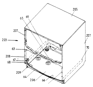
Figure 8 shows some of the structural features of the cabinet 203 of Figure 7.
Cabinet 203, which would normally be made from sheet steel, has the form of an
open-sided box with top and bottom panels 20~ and 206, two side walls 207 and
a
rear wall (not shown). The front of the cabinet is open except for a shallow
kick
plate 62 which is recessed back from the principal plane of the front of the
cabinet.
The open front of cabinet 203 is stiffened to resist lateral racking forces by
the
provision of portal frame members 63 and 64 as described in WO 93/12706. The
bottom of each of the two wash chambers 202a and 202b is configured to pass
over
the upper flanges 6~ and 66 of portal frame members 63 and 64 respectively.
Hav~cever, unlike the portal frame for the upper opening (and unlike the
cabinet
shown in WO 93/1206) portal frame member 64 is offset rearwardly from the
principal plane of the front of cabinet 61 and its effectiveness in resisting
racking
moments on the bottom half of cabinet 6I is reduced. This is overcome in the
present
invention by providing reinforcing plates 67 and 68 at the top of kick plate
62 and
structurally tying these plates together through the lower wash chamber slide
members (not shown) which are located in positions 69 and 70 indicated in
broken
lines. Plates 67 and 68, because of their rigidity and rigid connections to
the bottom
frame 64 and the side frames 208, respectively transfer racking forces applied
to the
side frames to the gusset areas 209 at each end of the bottom frame 64.
CLOSURE FOR SLIDING DRAWER WASH S'Y'STEM
In a washing machine as proposed here, where the wash chambers are
mounted as sliding drawers, the closing of the chambers prior to commencement
of
the wash cycle is more complicated than with conventional front loading or
above-
bench top loading machines. It is undesirable to have users manually close a
door to
seal the open-topped wash chamber prior to pushing the e~ctended 'drawer' back
into
the cabinet. It is preferable to have a closure which is actuated by the
action of
CA 02380564 2002-04-12
-12-
retracting the wash chamber back into the cabinet.
In Figure 1, a rigid closure or lid 217 is diagrammatically shown which is
mounted in the top of the cabinet 203 for closing the open top of wash chamber
20I .
Closure can be effected by mounting the lid in such a way as to allow it to be
mechanically forced downwardly on to the rim of wash chamber I as the chamber
is
retracted into cabinet 203. One means for achieving this type of sealing
action is
disclosed in WO 93/12706. In contrast to moving a rigid lid in both the
horizontal
and vertical direcrions by mechanical linkages in a parallelogram fashion to a
sealing
position during the last portion of travel of the wash chamber, the present
invention
provides alternative solutions.
The first of these is illustrated diagrammatically in Figures 9 and 10. In
this
case a rigid lid 2 I7 is used as previously described. but is fixed in
position in the top
of cabinet 203 and fitted with a peripheral inflatable gasket 18 located in
vertical
registration with rim 19 of wash chamber 201. In this embodiment when the wash
charr~ber is fully retracted, member 18 is inflated as shown in Figure 10 to
sealably
engage with rim 19. In this case member I 8 is the sealing member, but an
equally
suitable alternative would be to inflate a sealing member carrier 2~0
interposed
between the lid and sealing member 'y51 as shown in Figure 38.
A practical realisation of this embodiment is shown in more detail in Figures
11 and 13. Wash chamber 201 is formed with a flanged rim 19 which in use
provides
a seat for inflatable gasket 18. In Figure 11 wash tub 201 is indicated as
being fully
retracted within cabinet 3 with gasket 18 being inflated so as to sealably
engage rim
19.
A rigid lid 217 is fitted into the top of cabinet 203 and a peripheral
abutment
30 on lid 217 bears against the underside of the top of cabinet 3. Lid 217 is
essentially fixed in relation to cabinet 203. It is provided at the periphery
of its
underside with a channel 31 for retaining gasket 18.
Gasket 18 is moulded from an elastic plastics material and is formed as an
indefinite length. A ribbed extension 32 is integrally moulded on the top
surface of
the gasket to engage in channel 3 I in lid 217 to thereby engage the gasket to
the lid.
In one embodiment (not shown) a length of gasket material 18 sufficient to
CA 02380564 2002-04-12
-13-
trace out periphery of lid I7 is fitted in place and each end coupled to
opposite
connections on a T connector. The T connector provides air to both ends of
gasket
18 to inflate it when required. In a preferred embodiment diagrammatically
shown in
Figure 12, a length of gasket material sufficient to allow the ends 37 and 38
to
overlap is employed. The channel 31 in the lid also has overlapping parallel
ends to
support the gasket ends in close parallel relationship. End 37 of gasket 18
includes
an air-tight stopper 39 (or is otherwise sealed) while end 38 contains a
connector 40
for an air hose 41 which supplies air to inflate the gasket.
Even when the gasket is inflated a small amount of wash fluid will Ieak
between the overlapping ends of the gasket during the wash cycle of the
dishwasher.
Water egress through this gap must be controlled and for this purpose drainage
slots
42 are provided in the wash chamber rim 19 in the region of the exterior
gasket end
38 (see also Figure 13). Any water escaping between the gasket ends is
diverted
through the slots into a ducting 36. Ducting 36 is a separate plastics
moulding
attached to the rear surface of chamber 17. Water in ducting 36 is directed
back into
the bottom of chamber 17 through an aperture (not shown) in the chamber wall
located in registration with the sump portion 33 of duct 36.
In order to inflate gasket I 8. an air pump is provided which is preferably a
solenoid driven diaphragm pump. This pump is mounted inside the rear wall of
chamber 3 and couples to air hose 41. The diaphragm pump is energised using a
chopped DC supply provided by the dishwasher controller.
In use, when chamber 201 is loaded with dishes and fully retracted within
cabinet 203 and the dishwasher powered on, the air pump is activated to
inflate
gasket 18 to cause lid 217 to seal off the top of chamber 201. The end of the
inflation
cycle is indicated by the attainment of a desired pressure in gasket 18. The
dishwasher controller then initiates the wash cycle. The chamber remains
sealed
until the drying cycle terminates or until the user withdraws chamber 201 from
cabinet 203. During this period the air pump may be cycled on from time to
time to
ensure adequate sealing pressure is maintained in gasket 18.
;0 A further embodiment is shown in Figure 14 where lid 217 and the rim 19 of
wash chamber 201 are provided with complementary inclined edges along the
sides
CA 02380564 2002-04-12
- 14-
thereof. A resilient sealing member is disposed about the periphery of lid I7.
When
wash chamber 201 is fully retracted in cabinet 203 it seals against lid 17 by
virtue of
the wedging action that results as a result of the fore-aft inclinations of
the rid and
chamber rim.
In a further alternative configuration (not shown) a flat rigid lid is
provided
with a peripheral flexible gasket which cooperates with means on the wash
chamber
rim so that positive sealing between the lid and wash chamber is achieved by a
pure
sliding action when the chamber is retracted into the cabinet.
Figures 15 to 17 show alternative embodiments where instead of the use of a
rigid lid, a flexible closure is used. In Figure 15 a curtain type closure 24
is f xed
along edge 25 to the rear segment 26 of wash chamber rim 19. Curtain 24 is
retractably stored on a spring-loaded roller 27 mounted in the top front of
the
dishwasher cabinet 203. When wash chamber 201 is withdrawn, curtain 24 is
taken
up on toiler 25 whereas when the wash chamber is retracted, curtain 24 is
played off
roller 25 to fully cover the open top of the wash chamber 201.
Figure 16 shows a flexible closure 27 provided with a concertina type
configuration and mounted in slides provided in the top sides of the
dishwasher
cabinet. When the wash chamber 201 is withdrawn from cabinet 203 as shown in
Figure 17, closure 27 folds up due to concertina action whereas when the wash
chamber is retracted as shown in Figure 16 a closure 27 is opened out so as to
lie flat
along the top of the wash chamber.
A further embodiment is shown in Figure 18 and 19. In this embodiment lid
217 is fitted with an inflatable annular member about its outer edge and this
member
is inflated as shown in Figure 19 to sealably engage against the side of the
interior
wall of wash chamber 201. In this case the rear wall of the wash chamber is
reduced
in height to allow the wash chamber to slide into the cabinet notwithstanding
that the
lid is fixed in a vertical position lower than the top edge of the chamber
walls.
In addition to using a moving or expanding sealing member onto the top of
the wash chamber when it is retracted into the cabinet a separate seal support
carrier
may be interposed between the periphery of the lid and the sealing member with
closure being achieved by lowering the support carrier. This is shaven in
Figure 39,
CA 02380564 2002-04-12
-15-
where a seal support carrier 252 is attached to lid 2I7 by an expandable skirt
253. A
variety of actuator means giving reciprocal motion can be used to move the
seal
carrier.
An alternative flexible closure arrangement is shown in Figure 42. An endless
~ belt 260 mounted on rollers 261 having a width equally to the width of the
wash
chamber and spacing between rollers approximately equal to the length of the
wash
chamber covers the top of the chamber when it is fully retracted.
The rollers 261 are mounted at a fixed height in the top of the washer
cabinet.
The top edge of the rear wall 262 of the chamber is fixed to the belt 260 so
that it is
rotated and given the same linear motion as the chamber as it is slid closed.
A
pressure pad 263 may be used to ensure sealing of the belt against the wash
chamber
and the belt may be stiffened by a series of spaced apart transverse battens.
In the embodiments so far described the closure 2 I 7 is essentially fixed in
the
vertical direction within cabinet 203, whether rigid or flexible. In the
following
embodiments the closure is moved downwards by various means to seaiably close
the open top of wash chamber 201.
A first such embodiment is shown in Figures 20 and 21. Here a peripheral
resilient sealing member 20 is disposed on the underside of lid 217 while an
inflatable annular member 21 is used to force lid ? 17 downward in a vertical
direction to seal against rim 19 of the wash chamber as shown in Figure 19.
A further embodiment is shown in Figures 22 and 23. Here lid 217 is
mounted in the top of cabinet 203 so as to be movable in a vertical direction
from the
position shown in Figure 22 to the position shown in Figure 23. Sealing is
achieved
by providing flange configurations around the edge of the lid and in the top
of the
wash chamber wall so that when closed, as shown in Figure 23, an impassable
labyrinthic fluid path 22 is formed to thereby effectively seal the wash
chamber. The
lid and wash chamber flange configuration form a pressure equalisation chamber
which ensures wash liquid does not escape. This configuration of lid can also
be
used in a fixed lid mode if the rear wall of the wash chamber is of reduced
height to
provide clearance for the lid flanges as it is slid into the closed position.
In addition to the Iabyrinthic path configuration sealing may be assisted by
CA 02380564 2002-04-12
- 16-
flexible deformable sliding members 264 shown in Figure 43 and/or by a linear
brush member 26~ shown in Figure 44.
An alternative means of raising and lowering a rigid lid is shown in Figure
40. Compression springs 253 apply a lifting force to lid 217 and maintain it
in a
normally open position. Tension springs 254 are used to apply a closing force
to the
lid when the wash chamber is fully retracted into cabinet 2U I . Tension is
applied by
a roller 255 attached to one end of the spring travelling over cam or ramp 256
prior
to full retraction of the wash chamber. A latch 257 maintains tension in the
spring
after the roller has passed over cam 256. This is released when it is later
desired to
raise the lid. A second latch 258 takes the downward force due to the extended
spring 254 until the wash chamber is fully retracted whereupon it releases
member
259 to allow a closing (lowering force) to be applied to lid 217.
Another mechanism for raising and lowering a rigid lid is shown in Figures
45 to 47. A cam and cam follower arrangement is used as follows. Lid 217 is
mounted in the top of cabinet 203 on compression springs 270 although
restricted
against horizontal movement. Wash chamber 201 is provided with cam surfaces
266
and 267 on the outside of each side wall which engage corresponding rollers
268 and
269 as the chamber is moved horizontally to the retracted position. Surface
266 first
contacts roller 268 and causes the front of lid 217 to lift as shown in Figure
46.
Similarly surface 267 contacts roller 269 and lifts the rear end of lid 217 as
the wash
chamber is retracted furthez. At the end of horizontal travel (Figure 4 7) the
rollers
move down into the semi-circular portions of cam surfaces 266 and 267 under
the
influence of springs 270 to tower the lid 2I? onto the top of the wash chamber
and
close it.
This cam and cam follower technique can be used with the wedged
configuration of lid and wash chamber walls which was shown in Figure 14. This
can assist in achieving an increased sealing force by providing a vertical
force
component in addition to the horizontal component caused by pushing the wash
chamber into the cabinet. A cam and cam follower arrangement can also be used
to
raise and lower the rear end of the lid in constructions where the front of
the lid is
pivoted about a transverse horizontal axle at a fixed height in the upper
front of the
CA 02380564 2002-04-12
-17-
cabinet.
WATER MANAGEMENT SYSTEM
In a dishwasher of the double wash tub configuration shown in Figure 7 water
may be transferred between the upper and lower tubs 202a and 202b to minimise
the
S total volume of water consumed in the wash cycles.
Referring to Figure 24, cabinet 203 contains an upper wash tub 202a and a
lower wash tub 202b. Each tub has a drain pump I35 fed by a soil pipe 57 from
drain sump I36. The soil pipe on wash tub 202a has a branch pipe 137 connected
to
a valve I38 with the configuration being such that when valve 138 is open
water
from upper tub 202a can flow through branch pipe 137 into lower wash tub 202b.
A typical wash programme for each wash tub will be: pre-rinse, wash, post-
rinse 1, post-rinse 2.
According to this aspect of the invention water used in the upper tub post-
rinse cycle 1 is provided to the lower wash tub for its pre-rinse cycle and
the water
used-f_or the upper tub post-rinse cycle 2 is provided to the lower wash tub
for its
wash cycle. Thus the dishwasher controller is programmed to implement this
sequence of events by staggering the wash cycles for wash tub 202a and wash
tub
202b so that the wash programme for tub 202b is not commenced until the end of
post-rinse cycle 1 for the upper tub 202a. At that point, valve 138 is opened
to allow
the rinse water from tub 202a to flow into tub 202b. The wash programme for
tub
202b then commences with a pre-rinse cycle using the water from tub 202a. If
the
post-rinse cycle 2 time period is the same as the pre-rinse cycle time period,
then at
the conclusion of post-rinse cycle 2 for tub 202a, the rinse water is
discharged into
tub 202b at the commencement of the wash cycle for that tub.
Other wash programmes may be constructed using the above concepts to
similarly conserve a greater or lesser de2ree of wash water.
DRAIN PUMP
Referring to Figure 25 the present washer (as was the case in WO 93/I2706)
uses a single motor to drive both the wash pump and drain pump impellers which
are
mounted at opposite ends of the motor rotor shaft. As in WO 93/12706 the rotor
rotates within a well in the washer floor while the motor stator is mounted
external
CA 02380564 2002-04-12
- 18-
to the well under the sliding wash chamber. The wash pump is active when the
motor rotates in one direction while the drain pump is active when the motor
rotates
in the opposite direction.
In Figure 25 motor rotor 105 is mounted coaxially within well 106 provided
S in removable central floor section 51 of the wash chamber. Rotor 105 is
splined onto
a drive shaft 52 which extends out of opposite faces of the rotor. The upper
portion
of drive shaft 52 carries a wash pump impeller 95 (pump casing and spray
system
not shown), while the lower section of the drive shaft carries a drain pump
impeller
54. The lower portion 58 of well 106 provides a casing within which impeller
54
operates to pump wash water draining into sump 5 8 into waste pipe ~ ?.
It is necessary to prevent soiled wash water from entering the gap between
well 106 and rotor 105 so as to reduce wear on the rotor and to eliminate the
possibility of jamming the rotor. In the present invention, a plastics sealing
ring 59 is
mounted on shaft 52 between the lower face of rotor 105 and the upper face of
impeller 54. However without further measures, seal 59 causes air induced into
the
drain pump to build up to such an extent that liquid priming of the pump may
be
impeded or prevented.
This problem is overcome in the present invention by ensuring soil pipe 57
leaves the drain pump sump at an inclination of around 6" from the horizontal
and
by appropriately shaping vanes 55 of the pump impeller. When soil pipe 57 is
upwardly inclined, air accumulated up against seal 59 can be bled off so that
it does
not extend below the level of point 60.
Referring also to Figure 26 the vanes 55 of impeller 54 are provided with a
vertical slot 61 at their roots to provide an annular gap in which trapped air
may
accumulate when the impeller commences rotating. This allows adequate priming
to
achieve proper operation of the drain pump.
HEATING ELEMENT PROTECTION
A heating element for the present dishwasher takes the form of an annular
plate which comprises pan of the floor of the dishwasher as in WO 93i 12706.
The
heating element shown in Figures 27 and 28 consists of a thick film circuit
120
printed on a substrate comprising a steel (or alloy of steel) plate 121
covered with a
CA 02380564 2002-04-12
- 19-
porcelain enamel coating 122. The enamel forms the dielectric and consists of
a
ground coat and a cover coat, each of which is separately fired. The thick
film
resistive circuit 120 consists of a palladium silver composition which is in
turn fired
on to the enamel coating. Alternatively polymer materials may be coated on the
steel
S plate to form the dielectric. These can be cured and do not need to be fired
in a high
temperature furnace as is the case with enamel.
If the element runs dry, temperature build up will be such that the thick film
track burns and open circuits to cause energy dissipation in the heater
element to
cease and thereby minimise excessively high temperature build up in the wash
tub
which may damage plastic supporting components. However, this inherent
protection is insufficient to meet some electrical standards and accordingly a
sensor
circuit which disconnects power from the element is provided. As the steel
plate 121
is earthed in use, over temperature in the element system is detected in the
present
invention by monitoring the leakage current to earth. It will be appreciated
that as
the enamel dielectric undergoes a local increase in temperature, some current
will
flow between the thick film 120 and the steel substrate 12I.
An earth leakage protection circuit suitable for providing protection for the
element system is shown in Figure 29. Element 120 is energised from the AC
mains
supply (phase P, neutral N) through series switching devices comprising a
triac 123
and a relay 124. A differential current transformer 125 is coupled to the AC
supply
to element 120 and produces a voltage in winding 126 if an out of balance
current
exists in the supply phase and neutral conductors. This will occur if there is
any
leakage of the heater supply to the earthed element plate 121.
An operational amplifier 127 monitors the voltage across transformer winding
126 and when the earth leakage current exceeds a predetermined maximum, say
20 mA, the output of operational amplifier 127 switches npn transistor i28
into
saturation mode. This allows excess current to flow from the 12 volt DC rail
supply
129 through 200 mA fuse I30, pnp transistor 133, relay coil 131 to earth. The
fuse
blows and removes the supply of current to the relay coil 131, thus opening
relay
switch 124 to disconnect supply from element 120.
The present inventit~n also provides a failsafe circuit for the earth leakage
CA 02380564 2002-04-12
-20-
triggering circuit described so far. This ensures that element 120 cannot be
turned on
in the event that the circuit described develops a fault.
Accordingly a resistor I32 supplies a small AC "bias" current (which may be
around ~ mA) through current transformer 125. This produces a small out of
balance
voltage across winding 126 which produces a positive voltage offset at the
output of
operational amplifier I27 which in turn causes enough current to flow through
transistor 128 to bias on transistor I33, thereby allowing enough current to
flow
through relay winding 131 and hold relay switch 124 on. The current in
transformer
winding I26 is insufficient to cause enough current to flow through fuse 130
and
transistor 128 to cause the fuse to blow. With this arrangement, if any part
of the
protection circuit fails, the current flaw through resistor 132 ceases, the
'bias' offset
in winding is no longer detected and transistor I 3 ~ is turned off to de-
energise the
relay causing switch 124 to open and remain open while this state exists.
DETERGENT DISPENSER
' A detergent dispenser for use in the present dishwasher is illustrated in
Figures 30 to 37. The detergent dispenser fits hehind the interior front wall
4 of the
wash chamber and is accommodated within the thickness of front panel 202 (see
Figure 1).
Refezring to Figures 30 to 32, the detergent dispenser is formed by providing
a moulded receptacle ~ within a substantially rectangular aperture 6 within
wash
chamber wall 4. A pivoted or hinged door 8, which closes off receptacle 5,
provides
a sub-frame to which detergent containers 9 and 10 are mounted. A vent 11
provides
a communication between receptacle ~ and the wash chamber even when door 8 is
closed. Vent 11 allows detergent to enter the wash chamber in a manner
described
below. Two water outlet nozzles 12A and I2B (only one nozzle is shown in
Figures
and 31) are positioned in the top of receptacle ~ and located so as to
discharge
water into detergent containers 9 and 10 respectively.
Operation of the detergent dispenser is as follows. Detergent is loaded into
the detergent containers 9 and 10 as shown in Figure 30. Door 8 is opened for
this
30 purpose. It is then closed and wash chamber 1, loaded with dishes, is
retracted into
cabinet 3. At the appropriate time in the wash cycle the dishwasher controller
opens
CA 02380564 2002-04-12
-21 -
a valve to allow water to discharge from nozzle 12B. This nozzle discharges
into the
smaller detergent container 10 in a rinse cycle prior to the main wash cycle.
However the action of the detergent dispenser will be explained with reference
to
nozzle 12A discharging into larger container 9. The discharge causes water to
mix
with the detergent in container 9 and flush the water,'detergent mixture out
of the top
of the container 9 to spill into receptacle ~. The detergent containers are
provided
with a small bottom aperture 13 {as shown in Figure 33) for drainage. The
aperture is
sufficiently small to prevent discharge of dry detergent. The waterldetergent
mix
then enters the wash chamber through vent I 1.
Receptacle ~ may be mounted in wash chamber wall 4 using clamps tightened
by screws which serve to compress an 0-ring to seal the dispenser flange to
wall 4 of
the wash chamber in a known way. The provision of water outlets in the moving
wash system means that a water supply hose ??9 must flexibly extend between
the
cabinet and the wash chamber into front panel 202. This is arranged together
with a
1 S drain _hose and electrical wiring to form a hose wiring bundle 228 as
shown in Figure
3.
The present dishwasher dispenser does not impinge on wash chamber
volume, does not rely on wash water to dispense detergent and has no moving
parts
that may be fouled during the dispensing cycle. While described for use in a
dishwasher of the sliding drawer type, it may be used in dishwashers of
conventional
design having a front opening door to the wash chamber.
In the preferred form the detergent dispenser is moulded from plastics in two
parts, namely receptacle 5 and door 8 as shown in Figures 3~ and 36. To reduce
components the water conduits and valve casings are integrally moulded in
receptacle ~. This can be seen in Figure 36. As previously mentioned, water
must be
controllably released in the detergent dispenser through either of nozzles 12A
or
12B. .~ two-way shuttle valve 151 is used to divert water entering the
dispenser
water inlet 152 between a respective outlet 1 ~ 3 or 1 ~4. Outlet 1 ~~
discharges into
the pre-rinse detergent container while outlet 1 ~3 delivers water into the
main wash
detergent container. The water paths and the valve casing are all provided
within the
detergent dispenser moulding.
CA 02380564 2002-04-12
_ 77
Two-way valve 151 which is shown in more detail in Figure 37, comprises a
seal 1 » reciprocated between one of two positions by a solenoid armature 156
within a solenoid coil (not shown).
The dishwasher controller at appropriate points in the wash cycle opens a
S valve to supply water to detergent dispenser inlet 1 ~?. This water flows
through
passageway 157 to port 158 of the two-way valve 1 ~ 1. If valve seal 15~ is in
the
position shown, water entering port 158 is able to exit through port 1 ~9 from
whence
it proceeds through passageway 160 which discharges through outlet I 53. The
water
so discharged then enters detergent container to function as previously
described.
1.0 If solenoid armature 156 is retracted, valve seal 155 abuts against valve
seat
161 to prevent water entering inlet port 158 from exiting through outlet port
159.
However. the water entering the valve body may exit through outlet port 162.
It then
enters into water passageway 163 to be subsequently discharged at outlet I54.
This
is the discharge point for the flushing of pre-rinse detergent container 10.
.'The detergent dispenser moulding also incorporates a rinse aid reservoir 164
and the rinse aid liquid is dispensed into the wash chamber in a metered
volume by a
pump 16~. This pump is preferably a solenoid operated diaphragm pump which is
supplied with pulsed DC and the volume of rinse aid dispensed is directly
proportional to the period for which pump i 6~ is activated.
20 A charge of rinse aid is admitted into the wash chamber during the main
wash
cycle as follows. A solenoid driven diaphragm pump connected on its suction
side to
a refillable rinse aid reservoir is energised with chopped direct current for
a
predetermined time. The time is pre-stored in the dishwasher controller and is
set to
deliver an optimum volume of rinse aid for normal washes.
:25