Note: Descriptions are shown in the official language in which they were submitted.
CA 02380619 2002-O1-29
WO 01/12911 PCT/US00/21343
1
CEILING SYSTEM WITH REPLACEMENT PANELS
CROSS REFERENCE TO RELATED APPLICATION
This application claims priority to U.S. provisional application No.
60/148834,
filed August 13, 1999. This application is hereby incorporated by reference as
if fully
disclosed herein.
BACKGROUND OF THE INVENTI0~.1
Field of the Invention
The present invention relates to coverings for the ceilings and walls of
building
structures and, more particularly, to a drop ceiling or a wall panel wherein
individual
panels are supported on a matrix of support members.
Description of the Relevant Art
The ceilings of building structures have taken numerous forms. Ceilings may be
left unfinished so that rafters or beams of the building structure itself are
exposed or the
rafters and beams may be covered as with drywall, wood strips, plaster or
other similar
finishes. Walls of building structures may be similarly finished.
Another popular ceiling system is commonly referred to as a drop ceiling where
a plurality of support bars are suspended from the unfinished ceiling so as to
form a
matrix having a plurality of side-by-side openings defined between the support
bars. The
openings are filled with panels which are typically rigid acoustical panels,
with the panels
being supported along their peripheral edge by the support bars. While such
drop ceilings
have met with some success, there are numerous disadvantages. One disadvantage
is that
there is very little variety in the aesthetics of the ceiling system since
most acoustical
panels have the same general appearance, with another disadvantage residing in
the fact
that the panels are rigid and brittle so that they are easily breakable and,
further, due to
their rigidity, they are difficult to insert into the opening provided
therefor inasmuch as
the support bars must partially protrude into the opening in order to provide
a support
surface for the panels.
CA 02380619 2002-O1-29
WO 01/12911 PCT/US00/21343
2
It is to overcome the shortcomings in prior art drop ceiling systems and to
provide
a new and improved cladding system for walls or ceilings that the present
invention has
been made.
SUMMARY OF THE INVENTION
The present invention pertains to a new and improved drop ceiling system
wherein a plurality of flexible panels are preferably removably supported on a
grid work
of support bars. The support bars may be of inverted T-shaped cross-sectional
configuration and form a matrix from longitudinally extending stringers and
laterally
extending cross-members. The flexible panels are sized to fit within the
openings defined
by the stringers and cross-members and rest upon ledges of the inverted T-
shaped support
members.
The panels can take numerous configurations but include at least one sheet of
somewhat rigid but flexible or foldable material preferably made of a fibrous
material
that is reinforced in one of numerous ways so that it can be folded or flexed
while being
1 S inserted into an opening in the supporting grid work and subsequently
unfolded above the
grid work so that it can be easily positioned on the supporting grid work. In
various
disclosed embodiments, the panel can be made to be collapsible or
compressible.
The sheet material can be reinforced by a second parallel sheet of material
with
support members bridging the space therebetween or it may be reinforced simply
by a
plurality of reinforcing members extended along an unexposed, or possibly even
exposed,
surface of the sheet material. Where multiple sheets of material are utilized,
support
members are provided for retaining the sheet materials in a desired spaced
relationship.
The panels so formed provide adequate insulation and also, in most instances,
provide an exposed planar surface that can be covered with a decorative film
of various
colors, grains or textural patterns to provide variety to the aesthetics of
the ceiling system
once it has been installed.
While the panels have been summarized and will be described hereafter in more
detail as forming part of a ceiling system, it will be apparent to those
skilled in the art that
with modification of the support system the panels could also be used in the
walls of a
building structure.
CA 02380619 2002-O1-29
WO 01/12911 PCT/US00/21343
3
Other aspects, features and details of the present invention can be more
completely understood by reference to the following detailed description of a
preferred
embodiment, taken in conjunction with the drawings and from the appended
claims.
BRIEF DESCRIPTION OF THE DRAWINGS
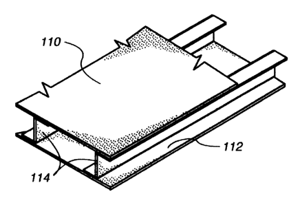
Fig. 1 is an isometric view of a panel formed in accordance with a first
embodiment of the present invention.
Fig. 2 is a fragmentary isometric view looking upwardly at a drop ceiling
system
in accordance with the present invention utilizing the panels of Fig. 1.
Fig. 3 is an enlarged fragmentary section taken along line 3-3 of Fig. 2.
Fig. 4 is an enlarged side elevation of the panel of Fig. 1.
Fig. 5 is an enlargement of a section of Fig. 4 showing support members for
the
panel in dashed lines.
Fig. 6 is an enlarged fragmentary isometric view of the panel of Fig. 1.
Fig. 7 is a view similar to Fig. 6 with a support member of the type shown in
dashed lines in Fig. 5 shown in solid lines.
Fig. 8 is a view similar to Fig. 5 with the panel being folded and with the
support
members shown in dashed lines where they would be incorporated if the panel
were fully
expanded as shown in Fig. 5.
Fig. 9 is a side elevation of the panel of Fig. 8 after having been fully
folded into
a flat condition.
Fig. 10 is a side elevation showing three panels in a fully folded condition
and
stacked upon each other.
Fig. 11 is a view similar to Fig. 5 showing the panel partially folded or bent
which
facilitates insertion of the panel into a position within the supporting grid
work for the
ceiling system.
Fig. 12 is a reduced side elevation similar to Fig. 11 again showing the panel
slightly folded or bent.
Fig. 13 is an exploded isometric view of the panel of Fig. 1 but including a
decorative film layer for covering the lower face of the panel of Fig. 1.
CA 02380619 2002-O1-29
WO 01/12911 PCT/US00/21343
4
Fig. 14 is an enlarged view of the circled area of Fig. 13
Fig. 15 is a side elevation of a panel as shown in Fig. 1 with end caps
running
along opposite ends of the panel to retain the panel in an expanded condition.
Fig. 16 is an enlarged fragmentary section taken along line 16-16 of Fig. 15.
Fig. 17 is a fragmentary isometric view with parts broken away of the panel
shown in Figs. 15 and 16.
Fig. 18 is a side elevation of a second embodiment of a panel in accordance
with
the present invention with the panel shown folded in dotted lines.
Fig. 19 is an enlarged fragmentary side elevation of a portion of the panel
shown
in Fig. 18.
Fig. 20 is a fragmentary isometric of the panel as shown in Fig. 19.
Fig. 21 is a side elevation of a third embodiment of a panel in accordance
with the
present invention with the panel being similar to the panel shown in Fig. 18
but with a
second parallel sheet of material.
1 S Fig. 22 is an enlarged fragmentary side elevation of a portion of the
panel of Fig.
21.
Fig. 23 is an enlarged fragmentary isometric view of the panel shown in Fig.
21.
Fig. 24 is a fragmentary isometric view of the reinforcement portion of the
panel
of Fig. 21 showing a first method of applying glue to the reinforcement.
Fig. 25 is a view similar to Fig. 24 with a second method of applying glue to
the
reinforcement material.
Fig. 26 is a view similar to Fig. 24 illustrating a third method of applying
glue to
the reinforcement.
Fig. 27 is a side elevation similar to Fig. 21 with the panel of Fig. 21
having been
partially compressed.
Fig. 28 is an enlarged fragmentary section of the panel as seen in Fig. 27.
Fig. 29 is a fragmentary section similar to Fig. 28 with the panel having been
further compressed.
Fig. 30 is an isometric view of the panel as shown in Fig. 27 partially
compressed.
Fig. 31 is a side elevation of a fourth embodiment of a panel formed in
accordance with the present invention.
CA 02380619 2002-O1-29
WO 01/12911 PCT/US00/21343
Fig. 32 is an enlarged fragmentary section of a portion of the panel as shown
in
Fig. 31.
Fig. 33 is a fragmentary section similar to Fig. 32 with the panel partially
compressed.
5 Fig. 34 is a fragmentary isometric of the panel shown in Fig. 31.
Fig. 35 is a side elevation of a fifth embodiment of a panel formed in
accordance
with the present invention.
Fig. 35A is an enlargement of the circled area of Fig. 36.
Fig. 36 is an enlarged fragmentary section illustrating a portion of the panel
shown in Fig. 35.
Fig. 37 is a fragmentary section similar to Fig. 36 with the panel having been
partially compressed.
Fig. 38 is a fragmentary isometric of the panel shown in Fig. 35.
Fig. 39 is a side elevation of a sixth embodiment of a panel formed in
accordance
with the present invention.
Fig. 40 is an enlarged fragmentary section of a portion of the panel shown in
Fig.
39.
Fig. 41 is a fragmentary isometric of the portion of the panel shown in Fig.
40.
Fig. 42 is a side elevation of a panel similar to that shown in Fig. 39 with a
parallel sheet of material added to the panel.
Fig. 43 is a fragmentary vertical section of a portion of the panel shown in
Fig.
42.
Fig. 44 is a fragmentary isometric of the portion of the panel shown in Fig.
43.
Fig. 45 is a side elevation of the panel shown in Fig. 39 with a fold or curve
formed in the panel.
Fig. 45A is an enlarged view similar to Fig. 45 showing the reinforcement
portion
of the panel of Fig. 45 in solid lines and parallel sheets connected to the
reinforcement
portion in dashed lines.
Fig. 46 is a fragmentary vertical section through a seventh embodiment of a
panel
formed in accordance with the present invention.
CA 02380619 2002-O1-29
WO 01/12911 PCT/US00/21343
6
Fig. 47 is an isometric view of an eighth embodiment of a panel formed in
accordance with the present invention.
Fig. 48 is an exploded isometric view of the panel shown in Fig. 47.
Fig. 49 is an isometric view of a secondary reinforcement strip used in the
panel
of Fig. 47.
Fig. 50 is an isometric view of the reinforcement structure for the panel
shown
in Fig. 47.
Fig. 51 is an isometric view of a sheet of material illustrating how the
secondary
reinforcement shown in Fig. 49 can be cut from such a sheet.
Fig. 52 is a side elevation of the panel shown in Fig. 47 looking upwardly and
to
the right from the lower lefthand side of the panel as shown in Fig. 47.
Fig. 53 is an enlarged section taken along line 53-53 of Fig. 52.
Fig. 54 is a section taken along line 54-54 of Fig. 53.
Fig. 55 is a section taken along line 55-55 of Fig. 56 and similar to Fig. 53
showing the panel partially compressed.
Fig. 56 is a section taken along line 56-56 of Fig. 55 and being similar to
Fig. 54
with the panel partially compressed.
Fig. 57 is a side elevation of a ninth embodiment of a panel formed in
accordance
with the present invention.
Fig. 58 is a fragmentary vertical section taken through a portion of the panel
shown in Fig. 57.
Fig. 59 is a fragmentary isometric of the portion ofthe panel illustrated in
Fig. 58.
Fig. 60 is a side elevation of a tenth embodiment of a panel formed in
accordance
with the present invention.
Fig. 61 is a fragmentary vertical section taken through the panel of Fig. 60.
Fig. 62 is a fragmentary isometric showing the portion of the panel
illustrated in
Fig. 61.
Fig. 63 is a side elevation of an eleventh embodiment of a panel formed in
accordance with the present invention.
Fig. 64 is an enlarged fragmentary vertical section showing a portion of the
panel
of Fig. 63.
CA 02380619 2002-O1-29
WO 01/12911 PCT/US00/21343
7
Fig. 65 is a fragmentary isometric showing the portion of the panel
illustrated in
Fig. 64.
Fig. 66 is a side elevation of a twelfth embodiment of a panel formed in
accordance with the present invention.
Fig. 67 is an enlarged vertical section taken through a portion of the panel
shown
in Fig. 66.
Fig. 68 is a fragmentary isometric view illustrating the portion of the panel
shown
in Fig. 67.
Fig. 69 is a side elevation of a thirteenth embodiment of a panel formed in
accordance with the present invention.
Fig. 70 is an enlarged vertical section taken through a portion of the panel
shown
in Fig. 69.
Fig. 71 is a fragmentary isometric illustrating the portion of the panel shown
in
Fig. 70.
1 S Fig. 72 is a side elevation of a fourteenth embodiment of a panel formed
in
accordance with the present invention.
Fig. 73 is an enlarged vertical section taken through a portion of the panel
shown
in Fig. 72.
Fig. 74 is a vertical section similar to Fig. 73 showing the panel partially
compressed.
Fig. 75 is a fragmentary isometric of the portion of the panel shown in Figs.
73
and 74.
Fig. 76 is a side elevation of a fifteenth embodiment of a panel formed in
accordance with the present invention.
Fig. 77 is an enlarged vertical section taken through a portion of the panel
shown
in Fig. 76.
Fig. 78 is a vertical section similar to Fig. 77 showing the panel partially
compressed.
Fig. 79 is a fragmentary isometric of the portion of the panel shown in Figs.
77
and 78.
CA 02380619 2002-O1-29
WO 01/12911 PCT/US00/21343
8
Fig. 80 is a fragmentary isometric view of a support member adapted for use in
connection with the panel shown in Fig. 60.
Fig. 81 is an end elevation of the support member shown in Fig. 80.
Fig. 82 is an end elevation of the support member incorporated into the panel
of
Fig. 60.
Fig. 83 is a side elevation of the panel of Fig.60 with the support member of
Fig.
80 incorporated therein.
DESCRIPTION OF THE PREFERRED EMBODIMENTS
A drop ceiling system 100 in accordance with the present invention utilizes a
conventional suspension system of elongated crisscrossing support members 102
forming
a matrix defining openings that are usually rectangular in shape in which a
panel in
accordance with the present invention can be disposed. The support members
typically
consist of horizontally disposed elongated stringers 102a that are suspended
in a
conventional manner and in parallel relationship in one direction across a
ceiling
structure usually at a vertical spacing of four to six inches from the
substructure of the
building structure in which the ceiling system is mounted. A plurality of
horizontal
cross-support members 102b extend in parallel relationship and perpendicularly
to the
stringers so that the quadrangular openings are defined therebetween. The
cross-
members are also suspended at the same elevation as the stringers. The
stringers and
cross-members are of inverted T-shaped cross-section as illustrated in Fig. 3
so as to
define horizontal shoulders 104 on either side of a vertical body 106, with
the shoulders
being adapted to support a peripheral edge of a panel formed in accordance
with the
present invention. As will be appreciated, the T-shaped support members 102
extend
peripherally around each quadrangular opening so that a shoulder is provided
to support
an entire peripheral edge of a panel.
Other types of suspension systems could be utilized, but a suspension system
of
the type described has proven to be very functional.
A first embodiment 108 of a panel in accordance with the present invention is
illustrated in Figs. 1-17. As probably best seen in Fig. 5, each panel 108
includes an
upper planar sheet 110, a lower planar sheet 112 and a plurality of parallel
reinforcement
CA 02380619 2002-O1-29
WO 01/12911 PCT/US00/21343
9
members 114 of substantially S-shaped cross-section. The upper and lower
planar sheets
as well as the reinforcement members are made of a somewhat rigid material
that can be
flexed. A material that has worked for this purpose is a non-woven fabric of
heat
resistant fibers bound together by a heat moldable polymeric resin matrix or a
thermal
setting resin matrix. For example, fiberglass fibers embedded in an acrylic
resin will
work for this purpose with the fibers preferably being relatively long and
thin. The length
of the glass fibers would be at least 1 /4 inch, but preferably %z inch and
especially at least
one inch. The thickness of the glass fibers would be no less than 7 microns
and no more
than 100 microns but preferably no more than 32 microns and especially 10-16
microns.
A material found suitable for this purpose is 1 OOGSM glass mat #8802
manufactured by
Johns Manville of Waterville, Ohio, or an alternative would be materials
available from
OJI Glasspen in Japan and Ahlstrom in Finland.
The upper and lower sheets of material are cut to a predetermined size which
corresponds with the area defined by the stringers 102a and cross-members 102b
of the
support system. As will be appreciated, the upper and lower sheets of material
are
retained in a parallel and separated relationship by the reinforcement members
114 which
are formed from elongated strips of material 116 that are pre-creased at
predetermined
locations so that they can be folded at right angles at those locations. The
strips of
material are also cut to pre-determined lengths to form the reinforcement
members.
The creases are provided at the locations where the strip material 116 is to
be
folded and these locations are spaced from each edge of the strip
approximately one-
quarter of the full width of the strip. In this manner, when the strips are
folded as
illustrated in Fig. 5, they define an upper flap 124 and a lower flap 126 and
an
intermediate body 128 which is approximately twice the width of each of the
flaps. The
crease lines, of course, allow the flaps to be folded relative to the
intermediate body. By
taking care when creasing the strips that the glass fibers not be damaged,
alternative
means for maintaining resiliency in the strip material need not be employed as
the glass
fibers provide the desired resiliency in the material. Each flap is provided
with an
adhesive on its outer surface to engage the adjacent sheet material 110 or 112
so as to be
securely bonded thereto. The adhesive could take numerous forms but a porous
adhesive
CA 02380619 2002-O1-29
WO 01/12911 PCT/US00/21343
made by EMS-Chemie AG of Domat/Ems, Switzerland and designated flame resistant
co-polyester adhesive #1533 has been found acceptable.
As will be appreciated, due to the creases in the reinforcement members, and
the
capability of the strip material 116 to bend along these creases, the
reinforcement
5 members by themselves may not necessarily retain the sheet material 110, 112
in spaced
relationship rendering the panel collapsible by moving the sheets of material
toward each
other while they slightly shift laterally relating to each other. To prevent
collapsing,
diagonal support members 130 of a more rigid plastic material or conceivably
the same
glass fiber reinforced resin material may be diagonally inserted into each
cell 132 defined
10 between the sheet material and adjacent reinforcement members. These
support members
130 are illustrated in dashed lines in Fig. 5 and in full lines in Fig. 7. The
support
members can be inserted in every cell or in spaced cells as is necessary to
support the
panel as desired. Even with the support members inserted in each cell,
however, the
panel can be slightly flexed or bent as illustrated in Figs. 11 or 12. As will
be
appreciated, due to the flexibility of the panels, they can be easily inserted
into the
openings between the stringers 102a and cross-members 102b even though the
overall
fully extended size of the panel 108 is substantially equal to the size of
that opening.
This, of course, provides a distinct advantage over systems in the prior art
where rigid
panels that could not be bent or flexed have to be inserted into an opening of
about the
same size.
By inserting support members at specified selected locations, but not in all
the
cells, the panel will take a curved shape that may be useful or appealing in
some
situations.
The reinforcement members 114 can be adhesively bonded to the sheet material
110, 112 in any suitable manner but, by way of example, the adhesive could be
provided
to cover the entire face of a flap 124 or 126, could be provided in continuous
lines along
the flap but not of the full width of the flap, could be provided in
intermittent lines along
the flap or other such applications. It is conceivable that the reinforcement
member could
also be heat welded or ultrasonically bonded to the sheet material as well.
It will be appreciated by reference to Figs. 8-10 that by removing the support
strips 130 from each cell, the panel 108 can be collapsed by folding the
reinforcement
CA 02380619 2002-O1-29
WO 01/12911 PCT/US00/21343
11
members 114 along their creases 122 so that the reinforcement members are
flattened and
extend in parallel relationship with the upper and lower sheets 110 and 112,
respectively,
as illustrated in Fig. 9. In this configuration, panels can be stacked as
illustrated in Fig.
into a small area for shipping purposes thereby saving considerable expense
when
5 shipping panels for use in a drop ceiling system.
With reference to Fig. 13, it will be appreciated that the panel 108 as
described
above can be modified by incorporating a decorative continuous layer of
elastomeric
polymer, preferably a thermoplastic or thermosetting polymeric film 134 or the
like, such
as a urethane or neoprene film, to the lower exposed face of the lower sheet
112, which
10 face is the face that is exposed to the interior of the room in which the
ceiling system is
mounted. The film material can be simply a flat sheet of colored material,
could be
furrowed or otherwise embossed with a pattern, or could have a wood grain or
other
decorative pattern imprinted thereon. There are numerous possibilities for
decorating the
lower surface of the panel and this film or related sheet of material can be
adhesively or
otherwise secured to the panel along the bottom face of the lower sheet of
material 112
of the panel. A decorative film as described above or other material may also
be applied
to the other panel embodiments of this invention, which are described below.
Examples of decorative coverings or films would be:
a) supported vinyl wall coverings made by Gen Corp. of Columbus, Miss.
b) unsupported vinyl films as used in wrapping operations from Alkor Draka
of
Munich, Germany.
c) flame resistant papers made by Pallas Inc. of Green Bay, Wisconsin.
d) flame resistant papers made by Permalin Products Co. of New York, New
York.
e) woven fiberglass mat from Johns Manville of Waterville, Ohio.
f) a flame resistant non-woven #TR2315B-1 from H & V of Floyd, VA
which has been quilted by Hunter Douglas Inc. of Broomfield, Colorado.
g) a flame resistant glass paint on a glass non-woven fabric with the paint
being manufactured by Keim of Holland. The glass non-woven fabric would come
from
Alkstrom of Finland.
CA 02380619 2002-O1-29
WO 01/12911 PCT/US00/21343
12
As an alternative to the diagonal support members shown in dashed lines in
Fig.
5, elongated end caps 136 as shown in Figs. I S-17 could be utilized. These
end caps
could simply be elongated U-shaped channel members of a rigid material which
are
adapted to fit snugly over the end of the aforedescribed panel 108 in
perpendicular
relationship to the longitudinal direction of the reinforcement members 114.
As will be
appreciated, the end caps prevent the panel from collapsing, as illustrated in
Figs. 8 and
9, and, of course, could be removed from the panel for shipping purposes and
installed
on the panel once the panels were ready for installation in a ceiling system.
As an
alternative the end caps could also be slit to fit within the open end of the
panel instead
of around the end. By way of example, the end caps could be made of a flame
resistant
polycarbonate or aluminum and adhesively secured to the panels 108.
Figs. 18-20 illustrate a second embodiment 138 of a panel in accordance with
the
present invention wherein a lower sheet material 140 is reinforced principally
in one
direction by a furrowed reinforcing sheet 142 that is folded as illustrated in
Fig. 19 to
define upwardly and downwardly opening trapezoidal channels 144. The
trapezoidal
channels would be bonded where the reinforcement member is in contiguous
abutting
face-to-face relationship with the lower sheet material 140. As mentioned
previously, the
bonding could be done in any variety of ways so long as a positive bond was
provided
between the reinforcing member and the lower sheet material. As will be
appreciated,
with an arrangement of this type, the panel can be flexed upwardly in a smooth
curve, as
illustrated in Fig. 18, and to a smaller degree downwardly but only in one
direction of the
panel. The trapezoidal channels 144 substantially prevent flexing in a
transverse
direction to that illustrated. This ability to flex the panel, however, allows
the panel to
be easily inserted into the opening between the stringers 102a and cross-
members 102b
in the support structure for the ceiling system. The stiffness of the panel
can also be
adjusted by the stiffness or rigidity of the lower sheet material 140.
In a third embodiment 146 of the present invention, seen in Figs. 21-30, the
ceiling panel 146 is formed similarly to the panel illustrated in Figs. 18-20
but wherein
an upper sheet material 148 is secured to the trapezoidal reinforcement member
142
along the top surface of the trapezoidal member. The upper sheet material can
be
adhesively bonded or otherwise secured to the reinforcement member in the same
or
CA 02380619 2002-O1-29
WO 01/12911 PCT/US00/21343
13
similar manner as the reinforcement member was secured to the lower sheet
material 140.
As illustrated in Fig. 24, the bonding of the reinforcement member 142 to the
sheet
material can be with a full layer of adhesive 150 or, as illustrated in Fig.
25, with a single
line of adhesive 150 or, as illustrated in Fig. 26, with parallel lines of
adhesive 150 or,
as mentioned previously, many other methods of applying adhesive such as
intermittently
or in dots or the like could also be employed. Again, heat welding or
ultrasonic bonding
may also be appropriate.
The completed panel 146 is probably best seen in Fig. 23 and, again, will bend
or flex in one direction of the panel but is substantially prevented from
flexing in a lateral
or perpendicular direction due to the trapezoidally shaped channels of the
reinforcement
member 142. The reinforcement member can be formed from a sheet of material
that has
been creased in opposite faces at spaced parallel locations and subsequently
folded.
The panel 146 can be compressed for shipping purposes, as illustrated in Figs.
27-
30, with a slight amount of compression probably not appreciably changing the
configuration of the panel other than to make it slightly thinner, but further
compression
causing the straight faces 160 of the reinforcement member to buckle or fold
into the
contoured configuration shown in Fig. 29. Accordingly, the panels can be
forcibly
compressed for shipping purposes so as not to occupy as much space within a
shipping
container and by utilizing an appropriate material for the panels, such as a
glass
reinforced resin as described previously, the panels will reassume their
normal
configuration of Figs. 21 and 22.
For purposes of the present disclosure, the term "compression" refers to
reducing
the thickness of a panel without allowing the upper and lower sheets to shift
laterally
relative to each other while the term "collapsing" refers to reducing the
thickness of a
panel while permitting lateral shifting of the upper and lower sheets relative
to each other.
If there were no upper sheet, such as in the embodiment shown in Figs. 18-20,
"compression" would occur if the furrowed reinforcing sheet were not allowed
to fold
laterally as if it were "collapsing" but rather was buckled straight
downwardly.
Fig. 31 illustrates a fourth embodiment 162 of the present invention where,
again,
upper and lower planar sheets of material 164 and 166, respectively, are
separated by a
furrowed reinforcement member 168 that defines upwardly and downwardly opening
CA 02380619 2002-O1-29
WO 01/12911 PCT/US00/21343
14
channels 170 of trapezoidal cross-section but in this embodiment of the
invention, the
engagement area of the reinforcement member 168 with each planar sheet member
164,
166 is less than the corresponding engagement areas of the panel shown in
Figs. 21 and
22. This allows for a more compressible panel and as will be appreciated, by
varying the
area of engagement between the reinforcement member and the planar sheet
members,
the compressibility of the panel can be regulated. Fig. 33 shows the panel 162
in a
somewhat compressed configuration but when utilizing appropriate resilient
materials,
the panel will return to the normal configuration illustrated in Fig. 32 upon
the release of
pressure due to the resiliency of the material utilized.
Figs. 35-38 illustrate a fifth embodiment 172 of the present invention which
is
somewhat similar to those shown in Figs. 21-22 and 31-32 so as to include
upper and
lower sheets ofplanar material 174 and 176, respectively, and a reinforcing
member 178
therebetween but wherein the reinforcing member is defined by upwardly and
downwardly opening channels 180 that are of substantially triangular
configuration. In
this arrangement, the engagement of the reinforcing member 178 with each
planar sheet
material 174, 176 is a relatively small area which allows even more
compressibility of
the panel. Fig. 35A is an enlargement of the circled area in Fig. 36 and shows
a line of
adhesive 182 along a substantially pointed line of engagement of the
reinforcement
member 178 with the upper planar sheet member 174.
A sixth embodiment 184 of the panel of the present invention is illustrated in
Figs. 39-41 and can be seen to include a lower planar sheet material 186, a
primary
reinforcement member 188 substantially of the type shown in Fig. 18, and a
secondary
reinforcement member 190 overlaid on the primary reinforcement member 188.
The primary reinforcement member 188 defines upwardly and downwardly
opening channels 192 of trapezoidal cross-sectional configuration and is
bonded to the
lower planar sheet material 186 along areas of engagement 194. The secondary
reinforcement member 190 is overlaid across the top of the primary
reinforcement
member and also defines upwardly and downwardly opening channels 196 of
trapezoidal
configuration but wherein the upwardly opening channels are wider than the
downwardly
opening channels. The downwardly opening channels are sized to conform with
and
receive the uppermost structure of a downwardly opening channel of the primary
CA 02380619 2002-O1-29
WO 01/12911 PCT/US00/21343
reinforcement member 188. The upwardly opening channels of the secondary
reinforcement member 190 are adapted to be received in an upwardly opening
channel
of the primary reinforcement member. The secondary reinforcement member is
secured
to the primary reinforcement member in any suitable manner such as with
adhesive and
5 either continuously or at intermittent locations only along horizontal areas
of engagement
198. The panel so formed, again, will flex in one direction but not as readily
flex in the
lateral transverse direction and Fig. 45 illustrates the panel when so flexed.
It will be
appreciated that the secondary reinforcement member flexes outwardly across
the
upwardly opening channels 192 of the primary reinforcement member to allow for
the
10 bend in the panel. This, of course, is permitted due to the fact that the
secondary
reinforcement member is not bonded to the primary reinforcement member in the
upwardly opening channels of the primary reinforcement member but only along
the top
or horizontal areas of engagement 198 with the primary reinforcement member.
Figs. 42-44 illustrate an alterative arrangement 200 to the panel illustrated
in Figs.
15 39 and 40, with this alternative arrangement being identical to the
arrangement shown in
Figs. 39 and 40 but wherein an is bonded to the secondary reinforcement member
190 in
parallel relationship with the lower planar sheet member 186. A panel so
formed could
also be bent as illustrated in Fig. 45A where the planar sheet members 186 and
202 are
illustrated in dashed lines.
Fig. 46 illustrates a seventh embodiment 204 of a panel in accordance with the
present invention wherein the panel 204 includes upper and lower planar sheets
of
material 206 and 208, respectively, a primary reinforcement member 210 and a
pair of
upper and lower secondary reinforcement members 212 and 214, respectively. The
primary reinforcement member has upwardly and downwardly opening channels 216
of
trapezoidal configuration but the primary reinforcement member is not directly
attached
to the planar sheet materials. Rather, the secondary reinforcement members 212
and 214,
respectively, are secured to the primary reinforcement member 210 along
horizontal
interfaces 218 between the respective members and, in turn, the secondary
reinforcement
members are secured to the planar sheet members along horizontal engagement
areas
220. The secondary reinforcement members are identical to each other but
inverted
relative to each other so as to be secured to the primary reinforcement member
across the
CA 02380619 2002-O1-29
WO 01/12911 PCT/US00/21343
16
top and bottom thereof substantially as described previously in connection
with the
embodiment of the invention shown in Figs. 39 and 40.
Figs. 47-56 illustrate an eighth embodiment 222 of the present invention
wherein
a pair of parallel planar sheets 224 and 226 are interconnected by a
reinforcement
member 228 that includes a primary reinforcement portion 230 and secondary
reinforcement portions 232 which provide rigidity in a transverse direction to
the primary
portion. As best illustrated in Figs. 49 and 50, the primary reinforcement
portion 230 is
a furrowed member substantially the same as the primary reinforcement member
of Fig.
39 thereby defining upwardly and downwardly opening channels 234 of
trapezoidal
cross-section. The secondary reinforcement portions 232 are insert strips, as
illustrated
in Fig. 49, that are adapted to be received in the upwardly opening channels
of the
primary reinforcement portion. Each secondary reinforcement strip has a cross-
sectional
configuration substantially identical to that of the primary portion, but the
planar side
walls 236 of the strip, which extend perpendicularly to the channels in the
primary
reinforcement portion, are tapered so as to converge downwardly thereby to
conform with
the downwardly convergent walls 23 8 of the upwardly opening channels of the
primary
portion of the reinforcement member. Accordingly, when the secondary
reinforcement
strips are positioned within the upwardly opening channels of the primary
reinforcement
portion, the reinforcement member is structured as illustrated in Fig. 50, and
it will be
appreciated that the panel has substantial rigidity in both longitudinal and
transverse
directions even though a slight degree of flexing is achievable due to the
characteristics
of the material from which the reinforcement member is made.
Fig. 51 illustrates a sheet of material 240 from which the secondary
reinforcement
portions can be cut and folded and as will be appreciated, a number of such
strips 232 can
be cut in a complimentary manner from the same sheet of material.
Figs. 55 and 56 illustrate the compressible nature of the panel 222 which is
permitted due to the flexible nature of the material from which the
reinforcement member
228 is made and as will be appreciated, depending upon the amount of pressure
applied
to the planar sheet members 224 and 226, the reinforcement members will buckle
into
the contoured configuration illustrated allowing the panel to assume a thinner
or
shallower cross-section, again, for shipping purposes. In other words, the
panels can be
CA 02380619 2002-O1-29
WO 01/12911 PCT/US00/21343
17
forcibly compressed into containers for shipment so as to occupy a minimal
amount of
space compared to that which would be occupied by the fully expanded panel.
Figs. 57-59 illustrate a ninth embodiment 242 of the panel of the present
invention which includes a lower planar sheet of material 244 and a
reinforcement
member 246 bonded or otherwise secured to the upper surface thereof to permit
easy
flexing of the panel in a downward direction but the reinforcement member
resists
flexing of the panel in an upwardly direction and transverse directions. The
reinforcement member has alternate upwardly and downwardly opening channels
248 of
trapezoidal cross-sectional configuration but the opening of each channel is
significantly
narrower than the opposed closed side of the same channel. As will be
appreciated, the
panel would be allowed to flex readily in a downward direction but not so
readily in an
upward direction and not so readily in a transverse direction. The
reinforcement member
is secured to the planar sheet material along areas of engagement in any
suitable manner
which could include adhesive applied in lines, continuously across the areas
of
engagement, along intermittent lines or dots or the like.
A tenth embodiment 250 of a panel formed in accordance with the present
invention is illustrated in Figs. 60-62. In this embodiment, a planar sheet of
material 252
is bonded or otherwise secured in a suitable manner to an overlying
reinforcement
member 254 that is similar to the reinforcement member shown in the embodiment
illustrated in Fig. 58 but wherein the upwardly opening trapezoidal channels
256 of the
reinforcement member are significantly wider than the downwardly opening
channels
258. This arrangement would permit not only flexing in the downward direction
but also
more flexing in the upward direction than would be permitted by the embodiment
shown
in Figs. 57-59. The lower exposed face of the sheet 252, which face is exposed
to the
interior ofthe room in which the ceiling system is mounted, can be modified
byproviding
it with a continuous elastomeric polymer (not shown). Preferably, the
elastomeric
polymer is a thermoplastic or thermosetting polymeric film, such as a urethane
or
neoprene film, as described previously with reference to Fig. 14, or a
urethane or
neoprene adhesive that bonds a decorative film, as described above with
reference to Fig.
14, on the lower face of the sheet 252. The elastomeric polymer allows the
panel 250 to
be substantially flexed or bent without visible creasing of the sheet 252. As
a result, the
WO 01/12911 CA 02380619 2002-0l-29 pCT/[JS00/21343
18
panel 250 can be manufactured in long lengths which can be stored and shipped
in rolled-
up form and then unrolled and cut to length for installation.
An eleventh embodiment 260 of a panel in accordance with the present invention
is illustrated in Figs. 63-65. This embodiment is identical to that
illustrated in Figs. 57
59 except that an upper planar sheet of material 262 is secured to a
reinforcement
member 264 across the top of the reinforcement member in the same or similar
manner
to which a bottom sheet material 266 is secured to the lower surface of the
reinforcement
member. This panel would have similar behavioral characteristics to that of
the panel
illustrated in Fig. 58 but would have slightly more rigidity and better
insulating qualities.
Figs. 66-68 illustrate a twelfth embodiment 268 of a panel formed in
accordance
with the present invention, with this embodiment including upper and lower
planar sheets
of material 270 and 272, respectively, that are secured to and separated by a
reinforcement member 274 having upwardly and downwardly opening channels 276
of
transverse trapezoidal configuration. The reinforcement member is similar to
that of Fig.
58 except that the trapezoidal cross-section is slightly enlarged so that the
opening of the
trapezoidal channels in both the upward and downward directions is slightly
greater than
that of the reinforcement member of Fig. 58.
A thirteenth embodiment 278 of a panel formed in accordance with the present
invention is illustrated in Figs. 69-71, with this panel, including upper and
lower planar
sheet materials 280 and 282, respectively, that are interconnected by and
spaced by a
reinforcement member 284. The reinforcement member is substantially identical
to that
illustrated in the embodiment of Figs. 60 and 61.
Figs. 72-75 illustrate the compressibility of the panel 268 described
previously
in connection with Figs. 66-68 and wherein it will be appreciated in Fig. 73
that the panel
can be compressed a slight amount without buckling the resilient walls of the
reinforcement member 274, but additional compression allows the walls of the
reinforcement member to further fold relative to each other into the
configuration
illustrated in Fig. 74. The walls will actually buckle so that the panel can
be substantially
compressed for cost savings during shipment.
Figs. 76-79 illustrate the compressibility of the panel 260 described
previously
in connection with Figs. 63-65 wherein it will again be appreciated that a
slight amount
WO 01/12911 CA 02380619 2002-0l-29 pCT/jJS00/21343
19
of compression, as seen in Fig. 77, is possible without buckling the resilient
walls of the
reinforcement member 264 but additional compression of the panel causes the
walls to
buckle and fold, as illustrated in Fig. 78, so that the panel is substantially
thinner thereby
occupying less space within a shipping container.
Figs. 80-83 illustrate a sixteenth embodiment 286 of a panel formed in
accordance
with the present invention. This panel is very similar to the panel described
previously
in Figs. 60-62 in that it includes a lower planar sheet of material 288 and a
reinforcing
member 290 with upwardly opening trapezoidal channels 292 spaced by closed
triangular
shaped channels 294. As will be appreciated, the upwardly opening channels
that are of
trapezoidal cross-sectional configuration define a space 296 along the upper
surface of
the reinforcement member between the triangular channels 294. A support member
298,
which is best seen in Fig. 80, is positioned across the top of the
reinforcement member
and extends perpendicularly to the channels in the reinforcement member so as
to provide
rigidity to the panel in a direction transverse to that provided by the
reinforcement
member so that the panel is rigidified in perpendicular directions.
The support member 298, which can be made of the same material as the planar
sheet 288 and the reinforcement member 284 and as seen in Fig. 80, includes a
downwardly opening channel-shaped body of inverted U-shaped cross-section proj
ecting
away from the reinforcement member and having outwardly directed flanges 300
from
which a plurality of tabs 302 are cut and bent to extend downwardly. The cross-
section
of the tabs 302 is best seen in Fig. 82 to conform generally to the walls and
space 296 of
the trapezoidal channels in the reinforcement member so as to mechanically
connect the
support member to the reinforcement member. The support member can, therefore,
be
mounted on the reinforcement member by positioning the support member
perpendicular
to the trapezoidal channels and sliding the support member along the length of
the
channels until it is desirably positioned. A plurality of the downwardly
opening support
members can be positioned at any desired spacing, as illustrated in Fig. 83.
The support
members, accordingly, substantially rigidify the panel so that it has very
little flexibility
in any perpendicular direction.
To the extent it is not clear from the above, the connection between the
various
components of the panels described can be achieved adhesively, ultrasonically,
through
CA 02380619 2002-O1-29
WO 01/12911 PCT/US00/21343
heat fusion or any other acceptable bonding system. The connections are made
where a
component engages an upper or lower sheet of the panel or along peaks defined
by a
component of the panel.
It will be appreciated from the above that an improved panel for use in a drop
5 ceiling system or in other similar uses has been provided that has variable
features for
adjusting the flexibility of the panel in longitudinal or transverse
directions and also for
varying the compressibility of the panel for shipping purposes. The exposed
faces of the
panels of this invention can also be modified by adding a continuous
elastomeric
polymer, such as a urethane or neoprene film or adhesive, as described, by way
of
10 example, with regard to the panels of Figs. 13 and 60-62 and/or a
decorative film as
described, by way of example, with regard to the panel of Fig. 13. Due to the
flexible
nature of the panels, they can also be easily inserted into the openings
defined by the
stringers and cross-members of a suspended support system and the panels will
not break,
as they are not brittle even when being flexed for insertion into the support
system. With
15 modifications to the suspension system, it will also be appreciated that
the panels could
be used in a wall of a building structure.