Language selection

Search

Patent 2380961 Summary

Third-party information liability

Some of the information on this Web page has been provided by external sources. The Government of Canada is not responsible for the accuracy, reliability or currency of the information supplied by external sources. Users wishing to rely upon this information should consult directly with the source of the information. Content provided by external sources is not subject to official languages, privacy and accessibility requirements.

Claims and Abstract availability

Any discrepancies in the text and image of the Claims and Abstract are due to differing posting times. Text of the Claims and Abstract are posted:

  • At the time the application is open to public inspection;
  • At the time of issue of the patent (grant).
(12) Patent: (11) CA 2380961
(54) English Title: EXHAUST MANIFOLD GASKET WITH INTEGRAL HEAT SLEEVE
(54) French Title: JOINT DE COLLECTEUR D'ECHAPPEMENT A MANCHON ISOLANT INTEGRE
Status: Deemed expired
Bibliographic Data
(51) International Patent Classification (IPC):
  • F02F 11/00 (2006.01)
  • F01N 13/00 (2010.01)
  • F01N 13/18 (2010.01)
(72) Inventors :
  • BATTISTONI, DANIEL C. (United States of America)
  • MIKOS, JAMES T. (United States of America)
(73) Owners :
  • DANA AUTOMOTIVE SYSTEMS GROUP, LLC (United States of America)
(71) Applicants :
  • DANA CORPORATION (United States of America)
(74) Agent: RIDOUT & MAYBEE LLP
(74) Associate agent:
(45) Issued: 2009-10-06
(22) Filed Date: 2002-04-08
(41) Open to Public Inspection: 2002-10-20
Examination requested: 2007-03-27
Availability of licence: N/A
(25) Language of filing: English

Patent Cooperation Treaty (PCT): No

(30) Application Priority Data:
Application No. Country/Territory Date
09/839,655 United States of America 2001-04-20

Abstracts

English Abstract

An improved exhaust manifold gasket for sealing between cylinder head port and flanged exhaust manifold of an internal combustion engine. The gasket includes an integral heat insulating sleeve for reducing thermal stresses on cylinder head port and gasket body, and is comprised of first and second metal layers fixedly secured together along a unitary plane. An aperture through the gasket provides for passage of high-temperature exhaust gases, wherein the first and second layers define at least one full sealing bead disposed about the circumference of the aperture. The second layer includes a plurality of circumferentially disposed leg portions symmetrically disposed about the exhaust aperture. The leg portions are adapted to receive the attached sleeve, which is positioned orthogonally to the unitary plane and adapted to extend into the exhaust port. The sleeve forms an insulating air gap between its exterior circumference and the interior circumference of the exhaust port.


French Abstract

Joint de collecteur d'échappement amélioré pour assurer l'étanchéité entre l'orifice de culasse et le collecteur d'échappement à bride d'un moteur à combustion interne. Le joint comprend un manchon isolant intégré qui réduit les contraintes thermiques de l'orifice de culasse et du corps du joint. Il est constitué d'une première et d'une deuxième couches solidarisées sur une surface plane. Une ouverture dans le joint fournit un passage pour le gaz d'échappement à haute température. La première et la deuxième couches forment au moins un bourrelet d'étanchéité placé autour du rebord de l'ouverture. La deuxième couche comprend de nombreuses parties pattes disposées sur la circonférence de façon symétrique autour de l'ouverture d'échappement. Les parties pattes sont conçues pour accueillir le manchon susmentionné, qui est placé à angle droit par rapport à la surface plane et conçu pour se rendre jusque dans l'orifice d'échappement. Le manchon forme une lame d'air entre la circonférence extérieure et la circonférence intérieure de l'orifice d'échappement.

Claims

Note: Claims are shown in the official language in which they were submitted.


WHAT IS CLAIMED IS:

1. An exhaust manifold gasket adapted for placement between a cylinder
head port and an exhaust manifold; said gasket comprising first and second
metal
layers fixedly secured together in a plane and having one medially positioned
aperture
therethrough, said first and second layers defining at least one full sealing
bead about
said aperture, said second layer including a plurality of circumferentially
depending
leg portions symmetrical with said aperture and orthogonal to said plane,
wherein said
gasket further comprises a cylindrical sleeve portion circumferentially
attached to said
leg portions, said sleeve parallel to said leg portions and also extending
orthogonally
with respect to said plane, said sleeve comprising a heat insulating medium
adapted to
extend into an engine exhaust port, said sleeve sized to define a
circumferential air
gap clearance between said port and said sleeve.

2. The exhaust manifold gasket of claim 1 further comprising said first
and second metal layers secured together via welding, and wherein said
aperture
diameter is less than said port diameter.

3. The exhaust manifold gasket of claim 1 wherein said gasket is adapted
for being bolted into place between a cylinder head port and a flange of an
exhaust
manifold, wherein said first and second metal layers are welded via spot
welding, and
wherein said sleeve is attached to said leg portions via spot welding.

4. The exhaust manifold gasket of claim 3 wherein said plurality of
circumferentially depending leg portions of said second metal layer define an
internal
diameter substantially equal to the external diameter of said sleeve, and
wherein said
sleeve is integrally fixed to said depending leg portions via welding.

5. The exhaust manifold gasket of claim 4 wherein said aperture and
sleeve are adapted for symmetrical alignment with a cylinder head exhaust
port.
-6-


6. The exhaust manifold gasket of claim 5 wherein said sleeve is adapted
to extend into said external circumference of said exhaust port, wherein
connection of
said gasket to the port is established via bolted attachment.

7. The exhaust manifold gasket of claim 6 wherein said first metal layer
defines an opening adapted to align with said internal diameter of said sleeve
and is
co-terminous therewith, wherein said diameter of said sleeve is smaller than
said
exhaust port diameter.

8. The exhaust manifold gasket of claim 7 wherein said first layer
comprises a radially inwardly extending flange portion that engages the top
surface of
said sleeve.

9. The exhaust manifold gasket of claim 8 wherein each of said metal
layers comprises a sealing bead, the beads mated together symmetrically in
said
gasket.

10. The exhaust manifold gasket of claim 9 wherein said first and second
metal layers comprise stainless steel.

11. The exhaust manifold gasket of claim 10 wherein said leg portions are
attached to the outside diameter of said sleeve by spot welding.

12. The exhaust manifold gasket of claim 10 wherein said sleeve
comprises a stainless-steel material.


-7-

Description

Note: Descriptions are shown in the official language in which they were submitted.


CA 02380961 2002-04-08

Express Mail Label No. ET056310547US
Attorney Docket No. 60680-1333
Dana Case 5256 VIC

EXHAUST MANIFOLD GASKET WITH INTEGRAL HEAT SLEEVE
BACKGROUND OF THE INVENTION

Field of Invention
The present invention relates to improved bolted-on automotive exhaust
manifold gasket assemblies for internal combustion engines, ancl more
particularly to
such gaskets having improved heat insulating characteristics as compared to
commonly known prior art exhaust manifold gaskets.

Description of the Prior Art
Those skilled in the art will appreciate the difficulty of maintaining a high
l o quality seal between the cylinder head exhaust port of an internal
combustion engine
and the exhaust manifold normally secured thereto via flange. Typically, an
exhaust
manifold gasket interfaces with, i.e. is affixed between, the cylinder head
exhaust port
of the engine and the engine exhaust manifold, indeed one of the hottest areas
of an
exterior engine environment. As a result of widely varying thermal cycles and
significant vibration, an exhaust gasket is subject to rapid deterioration if
its design is
inferior.
One means of enhancing longevity of such gaskets in recent years has been to
bracket together the exhaust manifold gasket with an insulating sleeve
installed into
the cylinder head exhaust port for reducing thermal stresses on both the
cylinder head
port and the exhaust gasket body. The associated structure, however, has been
formed
in several pieces, and is thus relatively cumbersome to install on the
assembly line, in
addition to being costly as result of the necessity of manufacturing extra
parts. A
consolidation of parts would be an attractive solution to resolve the issue.

SUMMARY OF THE INVENTION

The present invention is an improved exhaust manifold gasket for sealing
between a cylinder head exhaust port and a flanged exhaust manifold of an
internal
combustion engine. In a preferred form, the exhaust manifold gasket of this
invention
---2-


CA 02380961 2002-04-08

Express Mail Label No. ET056310547US
Attorney Docket No. 60680-1333
Dana Case 5256 VIC

contains an integral heat-insulating sleeve for reducing thermal stresses on
cylinder
head port and gasket body. The gasket is comprised of first and second metal
layers
fixedly secured together along a unitary plane. The gasket includes one
medially
positioned aperture for the passage of high-temperature exhaust gases, wherein
the
first and second layers define at least one full sealing bead disposed about
the
circumference of the aperture. Bolthole apertures are spaced radially
outwardly of the
exhaust gas aperture, and the second layer includes a plurality of
circumferentially
disposed leg portions symmetrically disposed about the exhaust aperture. The
leg
portions are positioned orthogonally to the unitary plane, and adapted to
receive the
attached sleeve designed to extend into the exhaust port. The sleeve is
laterally
positioned so as to form an air gap between its exterior circumference and the
interior
circumference of the exhaust port.

BRIEF DESCRIPTION OF THE DRAWINGS

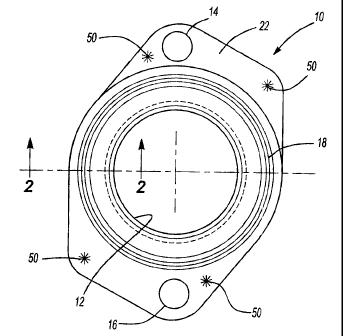
Figure 1 is a plan view of one preferred embodiment of an exhaust manifold
gasket that incorporates an insulating heat sleeve of the present invention.
Figure 2 is a cross-sectional view of a fragmentary portion of the same
embodiment of the exhaust manifold gasket, along lines 2-2 of Figure 1.
Figure 3 is a view of the same preferred embodiment of the exhaust manifold
gasket in its intended engine environment, interposed between a cylinder head
exhaust
port and an exhaust manifold flange, bolted into place as shown.

DETAILED DESCRIPTION OF THE PREFERRED EMBODIMENTS
Referring initially to Figures 1 and 3, a preferred embodiment of an exhaust
manifold gasket 10 has an aperture 12 in a medial portion of the gasket for
passage of
engine exhaust gases. The gasket 10 includes a pair of bolt apertures 14 and
16 at
spaced apart edges thereof for securenlent of the gasket 10 between an exhaust
port 36
of an internal combustion engine 40 and an exhaust manifold flange 44 of an
exhaust
manifold 42 attached to the port 36.

--3--


CA 02380961 2002-04-08

Express Mail Label No. ET056310547US
Attorney Docket No. 60680-1333
Dana Case 5256 VIC

Referring now to Figure 2, the gasket 10 includes an upper sealing bead 18 in
an upper metal layer 22. The bead 18 is symmetrically aligned with and
overlies a
lower mating sealing bead 20 in a lower metal layer 26. The layers 22 and 26
are
fixedly secured together e.g. via spot welds 50 (Figure 1) along a unitary
plane 28.
Depending downwardly from the planar tnetal layer 26 is a plurality of
circumferentially spaced orthogonal leg portions 24, positioned symmetrically
with
respect to the aperture 12. The portions 24 collectively define a
circumferential
retainer adapted to secure a cylindrical sleeve 30, which provides the gasket
10 with
an integrally attached insulating heat sleeve. In the described preferred
embodiment,
l0 the outside diameter 32 of the sleeve 30 is spot welded at locations 34 to
the
orthogonal legs 24. In one embodiment eight legs 24 are circumferentially
spaced
about the sleeve 32 and retain the sleeve to the described lower metal layer
26.

Referring now particularly to Figure 3, a port 36 of an internal combustion
engine 40 is shown in particular detail to demonstrate a preferred
installation of the
exhaust manifold gasket 10. Thus, an exhaust manifold 42 incorporates a flange
44
which mates with the port 36 via bolts (not shown) that extend through bolt
centerlines 44 and 48 respectivel.y. Those skilled in the art will appreciate
that the
bolts extend through bolt apertures 14 and 16 of the gasket 10, respectively,
and that
the positioning of the bolts will assure a symmetrical positioning of the
sleeve 30
within the port aperture 36. In the example shown, the sleeve 30 is
approximately 2.4
inches long and has an outside diameter of approximately 1 7/8 in. Each of the
legs
24 is approximately five millimeters or 0.2 inch wide. Also in the preferred
embodiment, the sleeve is sized relative to the port 36 so as to define an
insulating
circumferential air gap 52 between the outside diameter of the sleeve 32
(Figure 2)
and the interior diameter of the port 36 of approximately 60 thousands of an
inch.
With respect to other design parameters, the diameter of the aperture 12 will
be controlled by the internal diameter 31 of the sleeve 30. Thus in the
described
embodiment, a radially inwardly extending flange portion 23 of the upper metal
layer

-4
-


CA 02380961 2002-04-08

Express Mail Label No. ET056310547US
Attorney Docket No. 60680-1333
Dana Case 5256 VIC

22, situated at the boundary of the aperture 12, conveniently overlies the top
33 of the
sleeve to provide an insertion limit of the sleeve 30 during assembly.
Obviously, the
sleeve 30 must be inserted between the retainer leg portions 24 prior to the
spot
welding thereof to the legs 24 as described. It will thus be apparent that the
aperture
12 and the sleeve 30 will each necessarily be smaller in overall diameter than
the
diameter of the port 36.

It will be appreciated by those skilled in the art that sealing beads 18 and
20
are full beads as are used in metallic gaskets, and depending on the
application only
one circumferential bead may be necessary for a particular gasket design and
lo installation and yet be within the scope of this invention.

Finally, the preferred metal to be used for both of the gasket metal layers 22
and 26, as well as for the sleeve 30, is stainless steel. This is because of
the high
temperature ranges to which the manifold exhaust system is normally subjected.
Otherwise, the gasket 10 will have a short useful life due to the corrosive
effects of
oxidation. A preferred choice of a robust material for the intended
environment is
SAE 301 stainless steel for both layers and sleeve.

It is to be understood that the above description is intended to be
illustrative
and not limiting. Many embodirnents will be apparent to those skilled in the
art upon
reading the above description. T'he scope of the invention should be
determined,
however, not with reference to the above description, but with reference to
the
appended claims with full scope of equivalents to which such claims are
entitled.
--5-

Representative Drawing
A single figure which represents the drawing illustrating the invention.
Administrative Status

For a clearer understanding of the status of the application/patent presented on this page, the site Disclaimer , as well as the definitions for Patent , Administrative Status , Maintenance Fee  and Payment History  should be consulted.

Administrative Status

Title Date
Forecasted Issue Date 2009-10-06
(22) Filed 2002-04-08
(41) Open to Public Inspection 2002-10-20
Examination Requested 2007-03-27
(45) Issued 2009-10-06
Deemed Expired 2020-08-31

Abandonment History

There is no abandonment history.

Payment History

Fee Type Anniversary Year Due Date Amount Paid Paid Date
Registration of a document - section 124 $100.00 2002-04-08
Application Fee $300.00 2002-04-08
Maintenance Fee - Application - New Act 2 2004-04-08 $100.00 2004-03-17
Maintenance Fee - Application - New Act 3 2005-04-08 $100.00 2005-03-18
Maintenance Fee - Application - New Act 4 2006-04-10 $100.00 2006-03-21
Maintenance Fee - Application - New Act 5 2007-04-10 $200.00 2007-03-22
Request for Examination $800.00 2007-03-27
Maintenance Fee - Application - New Act 6 2008-04-08 $200.00 2008-03-18
Registration of a document - section 124 $100.00 2009-01-23
Maintenance Fee - Application - New Act 7 2009-04-08 $200.00 2009-03-18
Final Fee $300.00 2009-07-21
Maintenance Fee - Patent - New Act 8 2010-04-08 $200.00 2010-03-18
Maintenance Fee - Patent - New Act 9 2011-04-08 $200.00 2011-03-17
Maintenance Fee - Patent - New Act 10 2012-04-09 $250.00 2012-03-19
Maintenance Fee - Patent - New Act 11 2013-04-08 $250.00 2013-03-19
Maintenance Fee - Patent - New Act 12 2014-04-08 $250.00 2014-04-07
Maintenance Fee - Patent - New Act 13 2015-04-08 $250.00 2015-04-06
Maintenance Fee - Patent - New Act 14 2016-04-08 $250.00 2016-04-04
Maintenance Fee - Patent - New Act 15 2017-04-10 $450.00 2017-04-03
Maintenance Fee - Patent - New Act 16 2018-04-09 $450.00 2018-04-02
Maintenance Fee - Patent - New Act 17 2019-04-08 $450.00 2019-03-29
Owners on Record

Note: Records showing the ownership history in alphabetical order.

Current Owners on Record
DANA AUTOMOTIVE SYSTEMS GROUP, LLC
Past Owners on Record
BATTISTONI, DANIEL C.
DANA CORPORATION
MIKOS, JAMES T.
Past Owners that do not appear in the "Owners on Record" listing will appear in other documentation within the application.
Documents

To view selected files, please enter reCAPTCHA code :


To view images, click a link in the Document Description column. To download the documents, select one or more checkboxes in the first column and then click the "Download Selected in PDF format (Zip Archive)" or the "Download Selected as Single PDF" button.

List of published and non-published patent-specific documents on the CPD .

If you have any difficulty accessing content, you can call the Client Service Centre at 1-866-997-1936 or send them an e-mail at CIPO Client Service Centre.


Document
Description 
Date
(yyyy-mm-dd) 
Number of pages   Size of Image (KB) 
Claims 2002-04-08 2 85
Representative Drawing 2009-09-09 1 13
Cover Page 2009-09-09 2 52
Abstract 2002-04-08 1 27
Representative Drawing 2002-06-28 1 11
Description 2002-04-08 4 201
Drawings 2002-04-08 2 33
Cover Page 2002-10-04 1 45
Fees 2007-03-22 1 29
Assignment 2002-04-08 7 311
Fees 2004-03-17 1 32
Fees 2005-03-18 1 28
Fees 2006-03-21 1 26
Prosecution-Amendment 2007-03-27 1 25
Fees 2008-03-18 1 34
Assignment 2009-01-23 8 226
Correspondence 2009-07-21 1 35
Fees 2009-03-18 1 35