Note: Descriptions are shown in the official language in which they were submitted.
CA 02381154 2008-05-07
28283-79
CHEMICAL REACTOR AND METHOD FOR
CATALYTIC GAS PHASE REACTIONS
FIELD OF THE INVENTION
The present invention is a chemical reactor and method for gas phase reactant
catalytic reactions.
As used herein, the term "molecular diffusion" is used in its classic sense of
the
l0 transfer of mass based upon Brownian motion between adjacent layers of
fluid in
laminar, transition, or turbulent flow, and includes transfer of mass between
adjacent
layers of fluid that are stagnant.
As used herein, the term "Knudsen diffusion" means Knudsen flow, or free
molecule flow, wherein the mean free path of the molecules is long compared to
a
characteristic dimension of the flow field, for example the pore size of a
material through
which the molecules are diffusing. In Knudsen diffusion, molecules typically
collide
with walls rather than with other gas phase molecules.
BACKGROUND OF THE INVENTION
Many catalytic reactions begin with gas phase reactants, for example steam
reforming, partial oxidation, water gas shift and others. However, equipment,
specifically reactor volume is generally large because of mass and heat
transfer
limitations. Conventional reactors are operated with a gas hourly space
velocity from
about 1,000 to about 3600 hr-'. In other words, contact time is greater than I
second
because of the heat and mass transfer limitations.
These problems have been recognized and research is considering microchannel
reactors because the microchannels have been shown to offer less resistance to
heat and
mass transfer thus creating the opportunity for dramatic reductions in process
hardware
volume. Several types of microchannel reactors have been described in the
literature.
Franz et al., 1998 and Lowe et al., 1998 report applying a coating of the
active
catalyst (such as Pt, Ag, or other noble metal) directly to the microchannel
wall. This
approach has the disadvantage that the only usable surface area is that of the
microchannel wall.
-1-
CA 02381154 2002-02-04
WO 01/12312 PCT/US00/22817
Weissmeier and Honicke, 1998a-b report creating a porous interface directly
from
the microchannel wall material onto which the catalyst is deposited. An
aluminum wall
was anodized to create the porous alumina interface that had an average pore
diameter in
the nanometer size range (permitting only Knudsen diffusion) and a thickness
in the
range of tens of microns. Disadvantages of this approach include that it is
only
applicable for aluminum, and limited surface area. The anodized walls formed a
two-
dimensional array of 700 identical microchannels.
Tonkovich/Zilka et al., 1998 reported packing catalytic powders directly
within
an array of parallel microchannels as a packed microbed. A disadvantage was a
tendency
1o to create relatively large pressure drops by forcing the fluid to flow
through the packed
microbed.
Tonkovich/Jimenez et al., 1998 reported placing a palladium catalyst supported
on a metallic nickel foam within a cavity (more than an order of magnitude
larger than a
microchannel) and then sending the effluent to an array of microchannels to
exchange
heat. Again, a disadvantage was large pressure drop through the metal foam.
Hence, there is a need for a chemical reactor for catalytic reactions with
fast
kinetics that has a small reactor volume with a low pressure drop.
BACKGROUND REFERENCES
Franz, A.J., Quiram, D., Srinivasan, R., Hsing, I-M., Firebaugh, S. L.,
Jensen, K. F., and
M.A. Schmidt, 1998, New Operating Regimes and Applications Feasible with
Microreactors, Proceedings of the Second International Conference on
Microreaction
Technology, New Orleans, LA, p 33-38.
Lowe, H., Ehrfeld, W., Gebauer, K., Golbig, K., Hausner, 0., Haverkamp, V.,
Hessel,
V., and Richter, Th., 1998, Microreactor Concepts for Heterogeneous Gas Phase
Reactions, Proceedings of the Second International Conference of Microreaction
Technology, March 1998, New Orleans, Louisiana, p. 63-74.
Tonkovich, A. Y., Zilka, J. L., Powell, M. R., and C. J. Call, 1998, The
Catalytic Partial
Oxidation of Methane in a Microchannel Chemical Reactor, Proceedings of the
Second
International Conference of Microreaction Technology, March 1998, New Orleans,
LA,
p. 45-53.
Tonkovich, A. Y., Jimenez, D. M., Zilka, J. L., LaMont, M., Wang, Y., and R.
S.
Wegeng, 1998, Microchannel Chemical Reactors for Fuel Processing, Proceedings
of the
Second International Conference of Microreaction Technology, March 1998, New
Orleans, LA, p. 186-195.
-2-
CA 02381154 2007-10-16
28283-79
Weissmeier, G., and Honicke, D., 1998a,
Strategy for the Development of Micro Channel Reactors for
Heterogeneously Catalyzed Reactions, Proceedings of the
Second International Conference on Microreaction Technology,
New Orleans, LA, p. 24-32.
Weissmeier, G., and Honicke, D., 1998b,
Microreaction Technology: Development of a microchannel
reactor and its application in heterogeneously catalyzed
hydrogenation, Proceedings of the Second International
Conference on Microreaction Technology, New Orleans, LA,
p. 152-153.
SUMMARY OF THE INVENTION
In one reactor embodiment, the invention provides
a chemical reactor comprising: (a) at least one reactor
microchannel having at least one wall defining a bulk flow
path through which at least one gas phase reactant passes;
(b) a catalyst structure,comprising a catalyst material
wherein said at least one gas phase reactant contacts said
catalyst structure and reacts to form at least one product,
wherein said catalyst structure comprises: (c) a porous
material having a first porosity that permits molecular
diffusion therein, said porous material further having a
length, a width and a thickness, and a porosity surface
area, said porous material defining at least a portion of
said at least one wall of said at least one reactor
microchannel; wherein, during operation, said at least one
reactant enters said at least one reactor microchannel in
said bulk flow path, flowing past and in contact with said
porous material, a portion of said at least one reactant
molecularly diffuses into said porous material and reacts
therein to form said at least one product that molecularly
-3-
CA 02381154 2007-10-16
28283-79
diffuses into said bulk flow path, thereby transporting said
at least one product from said reactor.
In a further reactor embodiment, the invention
provides a chemical reactor comprising: at least one
reaction chamber comprising at least three layers: a first
layer comprising a first porous catalyst material; a second
layer comprising a heat exchanger and at least one fluid
flow path through said second layer, said second layer
disposed in the reaction*chamber such that fluid passing
through the first layer can pass through said at least one
fluid flow path, and a third layer comprising a second
porous catalyst material said third layer disposed in the
reaction chamber such that fluid passing through the second
layer can pass into said.second porous catalyst material;
wherein said first layer has contiguous channels having
dimensions of channel height, channel width and channel
length; wherein said at least one of said contiguous channel
comprises a channel height or channel width that is 0.1
micrometers to about 2 mm; wherein at least part of said at
least one of said contiguous channels comprises said first
porous catalyst material; and wherein said first porous
catalyst material has a pore volume of 5 to 98% and more
than 20% of the pore volume comprises pores having sizes of
from 0.1 to 300 microns.
In a still further reactor embodiment, the
invention provides a chemical reactor comprising: at least
one reaction chamber comprising at least one porous catalyst
material and at least one open volume wherein each of said
at least one reaction chamber has an internal volume defined
by reaction chamber walls; wherein said internal volume has
dimensions of chamber height, chamber width and chamber
length; wherein said at least one reaction chamber comprises
a chamber height or chamber width that is about 2 mm or
-3a-
CA 02381154 2007-10-16
28283-79
less; wherein, in a zone wherein said chamber height or
chamber width is about 2 mm or less, said chamber height and
said chamber width define a cross-sectional area; said
cross-sectional area comprising a porous catalyst material
area and an open area, wherein said porous catalyst material
area occupies 5% to 95% of the cross-sectional area and
wherein said open area occupies 5% to 95% of the cross-
sectional area; wherein said open area in said cross-
sectional area occupies a contiguous area of 5 x 10⁻⁸ to 1 x
10-2 m2 and wherein said porous catalyst material has a pore
volume of 5 to 98% and more than 20% of the pore volume
comprises pores having sizes of from 0.1 to 300 microns.
In a method aspect, the invention provides a method
for a catalytic chemical reaction with at least one gas phase
reactant, said method having the steps of flowing said at
least one gas phase reactant past a catalyst material and
reacting said at least one gas phase reactant to form at
least one product; comprising: (a) providing said catalyst
material as a porous structure having a porosity that permits
molecular diffusion therein, said porous structure further
having a length, a width and a thickness, said porous
structure defining at least a portion of at least one wall of
a microchannel defining a bulk flow path through which said
at least one reactant passes; (b) flowing said at least one
reactant through said microchannel, past and in contact with
said porous structure containing said catalyst material, a
portion of said at least one reactant molecularly diffusing
into said porous structure and reacting therein wherefrom
said at least one product molecularly diffuses into said bulk
flow path thereby transporting said at least one product from
said reactor.
In a further method aspect, the invention provides
a method of hydrocarbon steam reforming comprising: passing
-3b-
CA 02381154 2007-10-16
48283-79
a reactant stream comprising steam and hydrocarbon into at
least one reaction chamber; said reaction chamber having an
internal volume wherein said internal volume has dimensions
of chamber height, chamber width and chamber length; wherein
said at least one reaction chamber comprises a chamber
height or chamber width that is 2 mm or less; wherein said
at least one reaction chamber has a beginning and an end and
wherein said chamber length is the distance from the
beginning to the end of the reaction chamber; wherein said
reactant stream entering the beginning of the reaction
chamber is converted to a product stream exiting the
reaction chamber; said product stream comprising hydrogen,
carbon dioxide and carbon monoxide; wherein at least 70% of
said equilibrium conversion of the hydrocarbon entering the
beginning of said at least one reaction chamber is converted
to hydrogen, carbon monoxide and/or carbon dioxide; and
wherein said hydrocarbon has a contact time of less than 300
milliseconds.
In a still further method aspect, the invention
provides a method of conducting a chemical reaction
comprising: passing a gaseous reactant into a bulk flow
path of a reaction chamber; said reaction chamber having an
internal volume wherein said internal volume has dimensions
of chamber height, chamber width and chamber length; wherein
said at least one reaction chamber comprises a chamber
height or chamber width that is about 2 mm or less; wherein
a porous catalyst material is disposed within said internal
volume, wherein said porous catalyst material has a porous
internal structure such that the gaseous reactant can
diffuse molecularly within the material; wherein the gaseous
reactant reacts in the porous catalyst material to form at
least one product; and wherein said bulk flow path is
contiguous throughout said chamber length.
-3c-
CA 02381154 2007-10-16
28283-79
In one aspect, the present invention provides a catalyst material in a porous
structure having a porosity that permits molecular diffusion therein. The
porous structure
in one embodiment has a length, a width and a thickness, the porous structure
defining at
least a portion of at least one wall of the at least one microchannel.
The present invention provides a chemical reactor including: at least one
reaction
chamber comprising at least one porous catalyst material and at least one open
area
wherein each of said at least one reaction chamber has an internal volume
defined by
reaction chamber walls. The internal volume has dimensions of chamber height,
chamber width and chamber length. The at least one reaction chamber comprises
a
chamber height or chamber width that is about 2 mm or less. At a point where
the
chamber height or the charnber width is about 2 mm or less, the chamber height
and the
chamber width define a cross-sectional area. The cross-sectional area
comprises a
porous catalyst material and an open area, where the porous catalyst material
occupies
5% to 95% of the cross-sectional area and where the open area occupies 5% to
95% of
the cross-sectional area. The open area in the cross-sectional area occupies a
contiguous
area of 5 x 10'8 to 1 x 10"2 m2 and the porous catalyst material has a pore
volume of 5 to
98 % and more than 20% of the pore volume comprises pores having sizes of from
0.1 to
300 microns.
In another aspect, the invention provides a chemical reactor including at
least one
reaction chamber in which there are catalyst rods, plates or baffles having a
length to
thickness ratio of at least 10, and wherein the at least one reaction chamber
has an
internal volume defined by reaction chamber walls. The internal volume has
dimensions
of chamber height, chamber width and chamber length; and the at least one
reaction
chamber cornprises a chamber height or chamber width that is 2 mrri or less.
The catalyst
-3d-
CA 02381154 2002-02-04
WO 01/12312 PCT/US00/22817
rods, plates or baffles are disposed in said reaction chamber such that the
pressure drop
across the reaction chamber is less than 20% of the total system inlet
pressure.
In another aspect, the invention provides a chemical reactor including at
least
three layers. A first layer comprising a first porous catalyst material; a
second layer
comprising a heat exchanger and at least one fluid flow path through the
second layer.
The second layer is disposed in the reaction chamber such that fluid passing
through the
first porous catalyst material can pass through the at least one fluid flow
path, and
a third layer comprising a second porous catalyst material where the third
layer is
disposed in the reaction chamber such that fluid passing through the second
layer can
1 o pass into the second porous catalyst material. The first layer includes
continuous
channels having dimensions of channel height, channel width and channel
length. The
continuous channels have a channel height and/or channel width of 0.1
micrometer to 2
mm or less. The first porous catalyst material has a pore volume of 5 to 98 %
and more
than 20% of the pore volume comprises pores having sizes of from 0.1 to 300
microns.
The invention also includes a method of hydrocarbon steam reforming. In this
method, a reactant stream comprising steam and hydrocarbon is passed into at
least one
reaction chamber. The reaction chamber has an internal volume having
dimensions of
chamber height, chamber width and chamber length. The chamber height or
chamber
width is 2 mm or less. Each reaction chamber has a beginning and an end. The
chamber
length is the distance from the beginning to the end of the reaction chamber.
The
reactant stream entering the beginning of the reaction chamber is converted to
a product
stream that exits the reaction chamber. This product stream includes hydrogen,
carbon
dioxide and/or carbon monoxide; wherein at least 70% of said equilibrium
conversion of
the hydrocarbon entering the beginning of said at least one reaction chamber
is converted
to hydrogen, carbon monoxide and/or carbon dioxide. The process is conducted
under
conditions such that the hydrocarbon has a contact time of less than 300
milliseconds.
The invention further provides a method of conducting a chemical reaction in a
chemical reactor. In this method, gaseous reactant is passed into a first
compartment.
The chemical reactor includes a porous catalyst material, a first compartment
and a
second compartment. The first compartment and the second compartment include
open
spaces that permit bulk flow of a gas. The first compartment has an internal
volume
having dimensions of compartment height, compartment width and compartment
length.
The compartment height or width is about 2 mm or less. The porous catalyst
material is
-4-
CA 02381154 2002-02-04
WO 01/12312 PCT/US00/22817
disposed between the first compartment and the second compartment. The gaseous
reactant reacts within the porous catalyst material.
In another aspect, the invention provides a method of conducting a chemical
reaction in a chemical reactor in which a gaseous reactant is passed into a
first
compartment. The reaction chamber comprises a first compartment and a second
compartment, and a partition disposed between the first compartment and the
second
compartment. The partition comprises a fluid distribution layer or a
separating agent.
The first compartment has an internal volume having dimensions of compartment
height,
compartment width and compartment length. The first compartment includes a
porous
1 o catalyst material and at least one open space that permits bulk flow of a
gas and has a
compartment height or compartment width that is about 2 mm or less. In this
method a
gas travels through the partition. In preferred embodiments, the partition
includes a flow
distribution layer and a gaseous reactant convectively travels through the
flow
distribution layer from the second to the first compartment; and after
traveling through
the flow distribution sheet, reacts in a porous catalyst material contained
within the first
compartment. In another embodiment, the partition comprises a membrane or a
sorbent
which may selectively separate a product formed in the first compartment or
selectively
separate a reactant such as oxygen from air for use in a distributed feed
application.
The invention also includes a method of conducting a chemical reaction in
which
a gaseous reactant is passed into a bulk flow path of at least one reaction
chamber. The
bulk flow path is contiguous throughout said chamber length. The reaction
chamber has
an internal volume having dimensions of chamber height, chamber width and
chamber
length. The at least one reaction chamber comprises a chamber height or
chamber width
that is about 2 mm or less. A porous catalyst material is disposed within said
internal
volume, the porous catalyst material having a porous internal structure such
that the
gaseous reactant can diffuse molecularly within the material. The gaseous
reactant reacts
in the porous catalyst material to form at least one product.
While various aspects of the present invention are described and claimed in
terms
of one or two reaction chambers, it should be recognized that the invention is
envisioned
to operate most effectively where reactors contain multiple reaction chambers,
and
therefore the invention should not be limited to reactors and methods having
only one
reaction chamber. In many embodiments a characteristic dimension of about 2 mm
or
-5-
CA 02381154 2007-10-16
28283-79
less is selected because mass transport aiid heat transport on this scale can
be highly
efficient.
It should be recognized that many of the embodiments and reaction chamber
designs described herein are well-suited for combinations amongst the various
designs.
For example, the reaction chambers illustrated in Figs. l Od and 10e could be
integrated
with a conduit for carrying fluids from one layer to another (such as a
conduit from a
second catalyst layer back to the first catalyst layer). Therefore the
invention should be
understood as including combinations of the various designs and embodiments
described
herein.
The subject matter of the present invention is particularly pointed out and
distinctly claimed in the concluding portion of this specification. However,
both the
organization and method of operation, together with further advantages
thereof, may best be understood by reference to the following description
taken in
connection with accompanying drawings wherein like reference characters refer
to like
elements.
BRIEF DESCRIPTION OF THE DRAWINGS
FIG. I is a cross section of a microchannel with a porous material therein.
FIG. 2 is a cross section of the porous material with catalyst material
thereon.
FIG. 3 is a cross section of microchannels defmed by porous material.
FIG. 4a is a cross section of a microchannel with porous material surrounded
by
heat transfer microchannels.
FIG. 4b is a cross section of microchannels with porous material with a heat
transfer microchannel therebetween.
FIG. 5 is an isometric view of a cylindrical porous material.
FIG. 6 is a cross section of the porous material with a second porous material
on
porous surface area.
FIG. 7a is a block diagram of a microchannel steam reforming system.
FIG. 7b is an end view of a microchannel reactor.
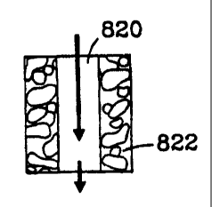
FIG. 8 illustrates cross-sectional schematic views of reaction chamber
configurations including (a) compartments with an intervening porous catalyst
material;
(b) a bulk flow channel disposed between porous catalyst layers; (c) dual
corrugated
catalyst; (d) corrugated catalyst with gas flow over the catalyst surface; (e)
corrugated
-6-
CA 02381154 2002-02-04
WO 01/12312 PCTIUSOO/22817
catalyst with gas flow through the catalyst; (f) wires of catalyst material;
(g) fibers; (h)
baffles having coatings of porous catalyst material; (i) baffles composed of
porous
catalyst material; (j) a porous matrix with bulk flow channels; and (k) a flow
distribution
sheet that distributes flow into a catalyst-containing compartment.
FIG. 9 illustrates schematic views of reaction chamber configurations
including
(a) a perspective view of catalyst channels with cross flow of a heat exchange
fluid; (b) a
cross-sectional view of a porous catalyst material that does not directly
contact the walls
of the reaction chamber; (c) top - a reaction chamber with a porous plug, and
bottom -
multiple flow channels with a mixing chamber; (d) shaped porous catalyst
material; (e) a
1 o u-shaped channel filled with porous catalyst material; (f) porous
dividers; and (g) mixing
reactant streams that are directed to flow between layers of porous catalyst
material.
FIG. l0a illustrates layers of a chemical reactor containing multiple sheets
of
porous catalyst material.
FIG. l Ob illustrates a view of a layer of porous catalyst material.
FIG. l Oc is a schematic illustration indicating recycled flow in a chemical
reactor.
FIG. l Od illustrates a cross-sectional schematic view of a reaction chamber
configuration from which products can be removed through a selectively
permeable
layer.
FIG. l0e illustrates a cross-sectional schematic view of a reaction chamber
configuration from which products can be removed through a selectively
permeable
layer.
FIG. 11 shows results of methane steam reforming testing of various reaction
chamber configurations.
FIG. 12 shows results of methane steam reforming testing of various reaction
chamber configurations.
DESCRIPTION OF PREFERRED EMBODIMENTS
In one aspect, the present invention includes a chemical reactor for a
catalytic
chemical reaction with at least one gas phase reactant. The reactor (FIG. 1)
has at least
one reactor microchannel 100 for flow of at least one reactant 102 and at
least one
product 104. An improvement according to the present invention is that the
reactor
further has a porous structure 106 wherein at least one reactant 102 reacts to
form at least
one product 104. The porous structure 106 has pores 200 or porosity that
resists bulk
-7-
CA 02381154 2002-02-04
WO 01/12312 PCTIUSOO/22817
flow (reactant 102, product 104) therethrough and permits molecular diffusion
(reactant
portion 102a, product portion 104a) therein. The pores 200 are defined by
porous
surface area 202 upon which the catalyst material 108 may reside. The porous
material
106 further has a length L, a width (not shown) and a thickness T, and in some
embodiments defines at least a portion of at least one wall of a bulk flow
path through
which the at least one reactant 102 passes.
A microchannel may be of any cross section defining the bulk flow path and is
characterized by a characteristic dimension less than 1 mm.
In operation, the at least one reactant 102 enters the at least one reactor
microchannel 100 in the bulk flow path, flowing past and in contact with the
porous
material 106. A portion of the at least one reactant 102a molecularly diffuses
transversely into the porous catalyst 106 and reacts wherefrom the at least
one product
104a molecularly diffuses transversely into the bulk flow path thereby
transporting the at
least one product 104 from the reactor.
Gas phase reactant catalytic reactions include but are not limited to steam
reforming, CO2 reforming partial oxidation, chlorination, fluorination,
hydrogenation,
dehydrogenation, nitration, water gas shift, reverse water gas shift,
autothermal
reforming, combustion, hydrocracking and hydrodesulferization. In steam
reforming,
gas hourly space velocity is preferably greater than 10,000, more preferably
greater than
50,000, and may be about 100,000 hr 1 corresponding to a residence time of
less than 10
milliseconds.
In a preferred embodiment, the width of the bulk flow path is less than or
equal to
about 1 mm. The thickness T of the porous structure 106 is less than or equal
to about 1
mm, and the length L preferably corresponds to a length of the microchannel of
less than
or equal to about 10 cm. The width of the porous structure 106 may vary but is
at least
about 20% and preferably at least about 50% of the circumference of the bulk
flow path.
The porous material 106 may be a catalytic material, for example catalytic
metal
or ceramic in the form of a foam or a felt. Alternatively, the porous material
106 may be
a porous support of a non-catalytic material with catalytic material 108
placed thereon.
Porosity may be geometrically regular as in a honeycomb or parallel pore
structure, or
porosity may be geometrically tortuous or random. Porosity may range from
about 30%
to about 98% with average pore size less than the smallest microchannel
dimension.
-8-
CA 02381154 2002-02-04
WO 01/12312 PCT/USOO/22817
Preferably pore size is from about 0.1 m to about 200 m permitting molecular
diffusion.
The porous material 106 alone may define the microchannels as in FIG. 3. In
this embodiment, it is possible to use a heat transfer fluid provided that the
porous
material 106 thickness T is sufficient to prevent mixing of the at least one
reactant 102 or
at least one product 104 with the heat transfer fluid. Alternatively, products
may diffuse
through the porous material 106 into a secondary fluid (not shown) to be
collected.
The porous material 106 may be placed adjacent a wal1400 of a non-porous
material, for example metal, as in FIG.'s 4a, 4b as an insert that may be
removable. The
1 o use of non-porous walls 400 permits the use of a heat transfer fluid 402
that is different
from the at least one reactant 102 and/or the at least one product 104. The
heat transfer
fluid 402 may flow countercurrent, cocurrent, crosscurrent or combinations
thereof in
relationship to the at least one reactant 102 and/or the at least one product
104.
The present invention may include cylindrical geometry as shown in FIG. 5. The
inside diameter represents the microchannel and has a diameter of less than or
equal to
about 1 mm. The cylinder may be of any closed cross sectional shape. Multiple
cylinders may be used. Cylinders may be formed as holes through a monolithic
block of
porous material 106. Alternate holes may be used for reactant/product and heat
transfer
fluid.
The residence time of reactant(s) in the reactor is preferably greater than
the
diffusion time for reactant(s) to contact the catalyst material. In some
preferred
embodiments, pressure drop across the reactor preferably ranges from about 0.1
psi to
about 5 psi.
Another embodiment is shown in FIG. 6 wherein the porous material 106 is a
first porous material having a second porous material 600 on porosity surface
area 202.
The catalyst material 108 resides in the second pores 602. The second pores
602 are
smaller than the pores 200, wherein the second pores 602 Knudsen diffusion
occurs
predominately.
Various embodiments of the present invention and ways of configuring a
catalyst
in a reaction chamber are illustrated in Figs. 8 and 9. The figures illustrate
single
reaction chambers; however, in preferred embodiments multiple reaction
chambers are
used in an integrated device when increased capacity is sought, preferably at
least 5
reaction chambers, more preferably at least 100 reaction chambers integrated
in a
-9-
CA 02381154 2007-10-16
28283-79
chemical reactor. For some low capacitv applications, only 1 to 5 channels may
be
required. Preferably, an integrated chemical reactor contains multiple
reaction chambers
that are connected in parallel, in series, or both. The reaction chambers are
preferably
integrated with other components such as microchannel heat exchangers or
devices such
as illustrated in Figs. 7a and 7b. The use of the inventive reaction chambers
in integrated
devices enables much higher rates of productivity in smaller volumes than
could be
achieved in conventional apparatus.
The term "bulk flow region" refers to open areas within the reaction chamber.
A
contiguous bulk flow region allows rapid gas flow through the reaction chamber
without
t 0 large pressure drops. In preferred embodiments there is laminar flow in
the bulk flow
region. Bulk flow regions within each reaction chamber preferably have a cross-
sectional area of 5 x 10⁻⁸ to I x 10"2 m2, more preferably 5 x 10"7 to I x 10-
4 m2. The
bulk flow regions preferably comprise at least 5%, more preferably 30-80% of
either 1)
the intemal volume of the reaction chamber, or 2) the cross-section of the
reaction
chamber.
The reaction chamber has dimensions of height, width and length. The height
and/or width is preferably about 2 mm or less, and more preferably 1 mm or
less (in
which case the reaction chambei falls within the classical definition of a
microchannel).
The length of the reaction chamber is typically longer. Preferably, the length
of the
reaction chamber is greater than 1 cm, more preferably in the range of I to 20
cm.
Typically, the sides of the reaction chamber are defined by reaction chamber
walls.
These walls are preferably made of a hard material such as a ceramic, an iron
based alloy
such as steel, or monel. More preferably, the reaction chamber walls are
comprised of
stainless steel or inconel which is durable and has good thermal conductivity.
In preferred embodiments, the reaction chamber(s) is in thermal contact with a
microchannel heat exchanger. This combination of reaction chamber(s) and heat
exchanger(s) can result in high rates of thermal transfer. Examples and more
detailed
description including the use of microchannel heat exchangers are provided in
U.S. patent no. 6,616,909. In preferred embodiments, the apparatus and methods
have
a heat flux of at least 0.6 W per cubic centimeter.
In place of, or in addition to, a microchannel heat exchanger, thermal
transfer can
occur between adjacent (or thermally contacting) reaction chambers -
preferably reaction
-10-
CA 02381154 2002-02-04
WO 01/12312 PCT/USOO/22817
chambers could be coupled such that heat from an exothermic reaction in one
reaction
chamber is transferred to an endothermic reaction in an adjacent reaction
chamber.
In some preferred embodiments, the reaction chamber has an inlet and an outlet
with a contiguous bulk flow path from the inlet to the outlet. In these
preferred
embodiments, the pressure drop from inlet to outlet is preferably less than
20%, more
preferably less than 10% of system inlet pressure. The pressure drop is
preferably less
than 350 kPa, and more preferably the pressure drop is less than 70 kPa. A low
pressure
drop is desired to reduce the size and cost of other system equipment such as
pumps and
compressors. In other embodiments, the reaction chamber may include a section,
such as
a porous plug, that interferes with bulk flow.
Equilibrium conversion is defined in the classical manner, where the maximum
attainable conversion is a function of the reactor temperature, pressure, and
feed
composition. For the case of hydrocarbon steam reforming reactions, the
equilibrium
conversion increases with increasing temperature and decreases with increasing
pressure.
The "porous catalyst material" described herein refers to a porous material
having
a pore volume of 5 to 98%, more preferably 30 to 95% of the total porous
material's
volume. At least 20% (more preferably at least 50%) of the material's pore
volume is
composed of pores in the size (diameter) range of 0.1 to 300 microns, more
preferably
0.3 to 200 microns, and still more preferably 1 to 100 microns. Pore volume
and pore
size distribution are measured by Mercury porisimetry (assuming cylindrical
geometry of
the pores) and nitrogen adsorption. As is known, mercury porisimetry and
nitrogen
adsorption are complementary techniques with mercury porisimetry being more
accurate
for measuring large pore sizes (larger than 30 nm) and nitrogen adsorption
more accurate
for small pores (less than 50 nm). Pore sizes in the range of about 0.1 to 300
microns
enable molecules to diffuse molecularly through the materials under most gas
phase
catalysis conditions. The porous material can itself be a catalyst, but more
preferably the
porous material comprises a metal, ceramic or composite support having a layer
or layers
of a catalyst material or materials deposited thereon. Preferably the support
is a foam
metal or foam ceramic.
Preferred major active constituents of the catalysts include: elements in the
IUPAC Group IIA, IVA, VA, VIA, VIIA, VIIIA, IB, IIB, IVB, Lanthanide series
and
Actinide series. The catalyst layers, if present, are preferably also porous.
The average
pore size (volume average) of the catalyst layer(s) is preferably smaller than
the average
-11-
CA 02381154 2002-02-04
WO 01/12312 PCT/US00/22817
pore size of the support. The average pore sizes in the catalyst layer(s)
disposed upon the
support preferably ranges from 10-9 m to 10-7 m as measured by N2 adsorption
with BET
method. More preferably, at least 50 volume % of the total pore volume is
composed of
pores in the size range of 10"9 m to 10-7 m in diameter. Diffusion within
these small
pores in the catalyst layer(s) is typically Knudsen in nature, whereby the
molecules
collide with the walls of the pores more frequently than with other gas phase
molecules.
In preferred embodiments, catalysts are in the form of inserts that can be
conveniently inserted and removed from a reaction chamber. Reaction chambers
(either
of the same type or of different types) can be combined in series with
multiple types of
l0 catalysts. For example, reactants can be passed through a first reaction
chamber
containing a first type of catalyst, and the products from this chamber passed
into a
subsequent reaction chamber (or a subsequent stage of the same reaction
chamber)
containing a second type of catalyst in which the product (or more correctly
termed, the
intermediate) is converted to a more desired product. If desired, additional
reactant(s)
can be added to the subsequent reaction chamber.
Catalytic processes of the present invention include: acetylation, addition
reactions, alkylation, dealkylation, hydrodealkylation, reductive alkylation,
amination,
aromatization, arylation, autothermal reforming, carbonylation,
decarbonylation,
reductive carbonylation, carboxylation, reductive carboxylation, reductive
coupling,
condensation, cracking, hydrocracking, cyclization, cyclooligomerization,
dehalogenation, dimerization, epoxidation, esterification, exchange, Fischer-
Tropsch,
halogenation, hydrohalogenation, homologation, hydration, dehydration,
hydrogenation,
dehydrogenation, hydrocarboxylation, hydroformylation, hydrogenolysis,
hydrometallation, hydrosilation, hydrolysis, hydrotreating (HDS/HDN),
isomerization,
methylation, demethylation, metathesis, nitration, oxidation, partial
oxidation,
polymerization, reduction, reformation, reverse water gas shift, sulfonation,
telomerization, transesterification, trimerization, and water gas shift.
Another advantage of the present invention is that good yields can be obtained
with short contact times. In preferred methods, the contact time is less than
100
milliseconds (ms), more preferably less than 50 ms and still more preferably
between 1
and 25 ms. Contact time may be reduced by reducing the diffusion distance
between the
bulk flow and the porous catalyst while concurrently reducing channel length.
At these
contact times, in a preferred embodiment of hydrocarbon steam reforming, at
least 70%,
-12-
CA 02381154 2002-02-04
WO 01/12312 PCTIUSOO/22817
more preferably at least 90%, of the equilibrium conversion of the hydrocarbon
entering
the beginning of said at least one reaction chamber is converted to hydrogen,
carbon
monoxide and/or carbon dioxide. Similar improvements can be obtained in other
processes.
Fig. 8a. illustrates a reaction chamber 802 having a first compartment 804
having
at least one dimension of about 2 mm or less, a porous catalyst material 806
and a second
compartment 808. This reaction chamber can be used in several ways. For
example, a
catalyzed reaction can be carefully controlled by passing one reactant (e.g.,
methane) 810
into the first compartment, passing a second reactant (e.g., water) 812 into
the second
compartment and, in this manner, effecting a controlled reaction within the
porous
catalyst material 806. Flow can be controlled by pressure differentials or by
plugging
one compartment (e.g. plug 814), and the product(s) formed in the porous
material can be
directed through outlet 816.
Fig. 8k illustrates apparatus 860 where a flow distribution layer 862
(typically a
sheet having random, regular, or spaced pores, slots, holes, or the like) can
distribute feed
864 along a length of the reaction chamber 866. The reaction chamber 866
preferably
contains a porous catalyst material 868 (although illustrated as a single
layer along the
length of the reaction chamber - thus enabling low pressure drop, it should be
recognized
that a porous catalyst material could have any of the configurations described
herein).
Product 870 exits the reaction chamber. Distributing the feed serves to lower
the local
partial pressure of one of the reactants. This has advantages for reactions
that are parallel
or series-parallel in nature, where the local concentration tends to favor one
reaction
pathway over another. For example, partial oxidation reactions can be improved
by this
distributed feed approach which increases selectivity to the desired product
over the
undesired deep oxidation products.
Fig. 8b illustrates an embodiment of the inventive reaction chamber in which a
bulk flow path 820 is disposed between porous catalyst material 822, although
some flow
may convectively travel through the large pores in the porous catalyst
material. Flow
through the large pores increases when the pore diameter of the porous insert
increases
and approaches an order of magnitude below the hydraulic diameter of the open
area.
This reaction chamber could be configured as a tube, with a ring or partial
ring of
catalyst, but is more preferably a planar arrangement. The planar arrangement
enables
economical stacking of reaction chambers with other components such as:
additional
-13-
CA 02381154 2002-02-04
WO 01/12312 PCT/US00/22817
reaction chambers, heat exchangers, etc. The contiguous, straight-through
configuration
of the bulk flow channel creates the opportunity to perform gas phase
catalysis with low
pressure drops.
Figs. 8c and 8d illustrate reaction chamber configurations in which corrugated
catalyst inserts 826 provide high surface area for gas phase catalysis while
contiguous
flow paths 828, 832 enable catalysis to be performed with low pressure drops.
The
inserts 826 either have a surface coating of a porous catalyst material or,
preferably, are
comprised of a porous catalyst material. A similar configuration is
illustrated in Fig. 9d.
Fig. 8e illustrates an embodiment in which a corrugated porous catalyst
material
1o 826 is disposed in the reaction chamber such that gas flow is partially
through, and
around the catalyst. This configuration ensures contact with the porous
catalyst;
however, this configuration has the disadvantage of significantly higher
pressure drops
but the advantage of more intimate contact of the reactants with the active
catalyst
surface.
Figs. 8f and 8g utilize catalyst fibers 836, 838. These fibers may, for
example, be
porous ceramic, metal or composite fibers. The parallel fibers 836 are
preferred because
they cause less of a pressure drop. The fibers 838 create tortuous flow
through the
reaction chamber. In either case, catalyst fibers are preferred over powders
because they
cause less pressure drop, can have better thermal conductivity, and can
provide a more
uniform and controlled surface for catalysis. The catalyst walls 840, 842 can
be ceramic
(for high temperature operation), metal (for good thermal conductivity),
composites, or
porous catalyst (for additional reactivity and/or addition or removal of gas
components).
Figs. 8h and 8i illustrate reaction chambers with baffles 846, 848. Baffles
846
comprise plates or rods composed of a porous catalyst material or that are
coated with a
porous catalyst material. Baffles 848 comprise plates or rods composed of a
porous
catalyst material. Flow can either be parallel 849 or nonparallel 847 or
differing
reactants can flow in differing directions (e.g. orthogonal reactant flows).
In either case,
there is a contiguous bulk flow through the chamber. These baffles can create
turbulence
and enhance contact of gaseous reactants with a catalyst. The baffles, which
preferably
comprise a thermally conductive metal, provide good heat transport to (or
from) the
reactor walls. The reaction chamber walls 854 may be of the same materials
described
above for walls 842.
-14-
CA 02381154 2002-02-04 m"u, U O/22VVV X 17
IPFA/US 0 5 OCT ')001
Fig. 8j illustrates a porous catalyst matrix material 850 within which there
are
contiguous bulk flow channels 852. The matrix 850 can be the reaction chamber
walls or
the entire article 855 can be an insert that fits into an opening. Preferably
the matrix
material contains I to 10,000 more preferably 5 to 1000 bulk flow channels
852. In a
preferred embodiment, the bulk flow channels 852 are essentially straight. In
another
embodiment, these channels are tortuous. In yet another embodiment, the
channels 852
are filled with a catalyst material and bulk flow of reactants and products is
primarily
through the matrix.
Fig. 9a illustrates a reactor 902 with reaction tubes/chambers 904, each of
which
may contain a porous catalyst material (not shown) in any of the
configurations described
herein. On the outside of these tubes is a bulk flow volume 906. In a
preferred
embodiment, a heat exchange fluid flows through the bulk flow volume; flow of
the heat
exchange fluid can be cross-flow, concurrent flow or counterflow to the flow
of gaseous
reactants and products.
Fig. 9b illustrates a configuration in which a porous catalyst material 908 is
disposed within the reaction chamber without direct contact to the reaction
chamber walls
910. In another embodiment (not shown), the material 908 comprises a core of a
large
pore structure (in which molecular diffusion occurs) and a small pore
structure (through
which Knudsen diffusion occurs) on the outer sides. Catalyst may be coated on
the small
pore structure, or on the large pore structure, or on both.
The top of Fig. 9c illustrates a reaction chamber 911 having a bulk flow path
912
and porous catalyst materia1914, 916. Porous catalyst materia1916 is in the
form of a
plug which serves to provide catalyst contact to any gaseous reactants that
remain
unreacted after passage through bulk flow path 912. The flow regime in this
example,
and in other figures, is typically laminar based upon the classical definition
of the
Reynolds number less than 2000. Although the flow regime may also be
transitional or
turbulent in the microchannels, this is less common. For laminar flow, there
will be
reactants that move along the centerline of the channel. Not all molecules may
have an
opportunity to diffuse to the porous catalyst and react. For those molecules
that do not
diffuse to the wall to react, this is referred to as `slip'. The overall
reactor conversion
may thus be a few percentage points lower than equilibrium would suggest
attainable.
The use of the porous catalyst material through the entire cross section for a
fraction of
the reactor length serves to reduce slip and enable overall conversions with a
closer
approach to equilibrium.
13
CA 02381154 2002 02 04 PMJ OO/`^ 2V.^ 1I
tpEAlUS 0 5 0CT 2001
The bottom of Fig. 9c illustrates a reactor comprised of multi reaction
chambers
922 and a mixing chamber 924. The mixing chamber combines gases from at least
two
reaction chambers 922. The mixing chamber helps to equalize concentration
between
multiple reaction chambers by mixing the possibly laminar flow streamlines and
helps to
ensure a higher overall conversion than if the at least two reaction chambers
were joined
into one chamber by reducing the centerline slip of reactants.
Fig. 9e illustrates a reactor in which the bulk flow from at least two
reaction
chambers 930, 932 flow into porous material 934. In an altemative mode of
operation,
flow enters through reaction chamber 930, through porous material 934 and out
through
reaction chamber 932. This embodiment also serves to reduce the possible slip
of
reactants and bring the overall reactor conversion closer to that predicted at
equilibrium.
Fig. 9f illustrates a forked configuration in which a gaseous reactant enters
a first
compartment 936, having a dimension of about 2 mm or less, and convectively
travels
past porous catalyst material 938 and then travels convectively through porous
catalyst
material 940. While traveling in compartment 936, the feed may diffuse to the
porous
catalyst and react. The gas exiting the porous catalyst material 940 flows
into second
compartments 942. The compartments 936 and 942 may or may not be offset. By
offsetting porous dividers formed by porous catalyst material 938, the gas
flows in
adjacent first compartments are further mixed to reduce the slip of reactants.
Fig. 9g illustrates a flow configuration where the feed flows along one side
of a
porous catalyst in the first flow path, makes at least one bend, and then
travels back along
the other side of the porous catalyst in the opposite flow direction to form
at least one
second flow path. In an alternate configuration, a second catalyst may be used
for the
second flow path. In another configuration, a wall may separate the porous
catalysts used
in the first and second flowpath.
Fig. IOa-lOc illustrates another aspect of the invention in which a heat
exchanger
504 is disposed between two layers of porous catalyst sheets or layers 502,
506. The
layers may be assembled as sheets or as an integrated device. In a preferred
embodiment,
a gas exiting the first porous catalyst sheet 502 then passes through at least
one array of
microchannels in the heat exchanger 504 and travels toward the second porous
catalyst
sheet 506. A separate heat exchange fluid is preferred in heat exchanger 504
to either
remove heat from an exothermic reaction in chamber 502 or to add heat for the
case of an
endothermic reaction in chamber 502. The flow of heat exchange fluid may be
either co-
1(0
'~'
CA 02381154 2002-02-04 M"NJ UU / 22 L~ 17
IpEMS 05 0CT 2001
current, countercurrent, or cross current. In an alternate embodiment the heat
exchanger
504 could operate in a recuperative heat exchange mode, whereby the cold
reactants
could be preheated in at least one first array of microchannels in heat
exchanger 504, then
fed to the reaction chamber in 502 to undergo an exothermic reaction, and then
cooled in
at least one second array of microchannels in heat exchanger 504 that is
exchanging heat
with the first array of microchannels in heat exchanger 504. The product
mixture from
the first reaction chamber 502 that travels through the heat exchange chamber
504 may
then travel to at least one second reaction chamber 506 to undergo a different
or similar
reaction.
This alternating structure can be repeated any number of desired layers. In a
preferred embodiment, the layers shown in Fig. 10a can be laminated and walls
placed
around the laminate to fonn a reactor. The reactor has appropriate openings,
valves, etc.
to control input of reactants output of products and flow of heat exchange
fluids. The
porous catalyst layers can be the same or can be different. For example,
products from
the first catalyst layer 502 can be subjected to a second reaction (different
from the first
reaction) possibly with the use of one or more porous catalysts (different
from the catalyst
on the first layer) at the second catalyst layer 506 to form a different
product. The porous
catalyst layers must be sufficiently porous to permit the flow of gases
through the layers
and preferably, these layers are comprised of the porous catalyst material
described
herein. The porous catalyst layer 502 and preferably other porous catalyst
layers (e.g.,
506), should have contiguous channels through the layer. The smallest width or
height
dimension of these channels is 0.1 micrometer to about 2 mm, preferably 0.3
micrometers
to 2 mm. A porous catalyst material is disposed in the layers such that gas
moving
through the layers contacts the porous catalyst material. These channels could
also be
any of the reaction chambers described herein. The length of channels can be
any length
including less than 2mm.
In another aspect, the invention can be defined to include a chemical reactor
including one porous catalyst layer 502 and a heat exchanger 504. Optionally,
fluid flow
through the heat exchanger can be directed into a reaction chamber such as any
of the
reaction chambers described herein.
The heat exchanger is preferably a microchannel heat exchanger. As illustrated
in
Fig. I Oc, the laminate can be configured such that a portion of flow from any
layer can be
recycled back upstream to again flow through all or part of the laminate.
Recycle may
1?
~~E11~n~'i1 cs~~
CA 02381154 2002-02-04
WO 01/12312 PCTIUSOO/22817
be desired to raise the conversion if thermodynamically attainable. As an
alternate
configuration, the product may be separated from the unreacted feeds while on
the
recycle path back to an earlier reaction section.
In Fig 10d, a product may be separated from the reaction chamber 520 as it is
formed through the use of an active separating agent 522 such as a membrane or
sorbent.
The continuous removal of products can drive otherwise equilibrium-limited
reactions to
completion. The products diffusing out of the porous catalyst 524 may further
diffuse
across the open area 526 to the active separating agent on the opposing wall.
For
example, the separating agent 522 can be a palladium membrane for the
selective
1 o removal of hydrogen gas. In an alternate embodiment shown in Fig 10e, the
products
may diffuse through the porous catalyst to the adjacent wall which is also an
active
separating agent.
Example 1
An experiment was conducted to demonstrate the present invention using 1
microchannel for methane steam reforming. The microchannel was placed within a
tube
furnace to provide the required endothermic reaction heat. The microchannel
was 1.52-
cm long and 0.66-cm high. The width (or opening) of the microchannel was
0.0762-cm
or 762-microns. The 0.0762-cm width included two porous structures that
covered
opposite walls and each had a width of 254-microns leaving a bulk flow path
between the
two porous structures of 254 microns. The porous structure contained a
catalyst of
13.8%-Rh/6%-MgO/Al203 on a metal felt of FeCrAl alloy obtained from
Technetics,
Deland, Florida. 13.8wt%Rh6wt%MgO/A1203 powdered catalyst was prepared by 1)
calcining a high surface area gamma-alumina at 500 C for 5 hours; 2)
impregnating the
gamma alumina with MgO using the incipient wetness method with an aqueous
solution
of magnesium nitrate; and obtaining an MgO modified gamma alumina support; 3)
drying the modified support at 110 C for 4 hours followed by 4) a second
calcination at
900 C for 2 hours; 5) impregnating the modified support with Rh203 with the
incipient
wetness method from a rhodium nitrate solution; 6) followed by a final drying
at 110 C
for 4 hours and a 7) final calcinations at 500 C for 3 hours to obtain a
powder of the
supported catalyst. The powdered catalyst was ball-milled overnight and slurry
dip-
coated on the FeCrAl felt until the desired loading is achieved. The coated
catalyst was
dried at 90 C overnight and calcined at 350 C for four hours. Prior to the
catalyst
-18-
CA 02381154 2002-02-04
WO 01/12312 PCT/US00/22817
evaluation, catalyst was reduced in 10%H2/N2 (100cc(STP)/min) at 110 C for
four
hours.
The methane inlet flowrate was 50.3-cc/min at standard conditions and the
water
(liquid) flowrate was 7.3 mL/hr, corresponding to a steam to carbon ratio of
approximately 3:1. The methane and water were preheated to near the reaction
temperature before entering the microchannel. Gas flow was in the bulk flow
path
between the porous structures had a Reynold's number less than about 500, and
molecular diffusion brought reactants and products to and from each pore
surface
containing the catalyst.
Results are shown in Table 1-1 of performance as a function of temperature for
very short residence times (less than 10-milliseconds).
Table 1-1: Performance data in single microchannel
Temperature Residence time Methane CO selectivity Pressure drop
(milliseconds) conversion (%) (%) (psi)
650 2.3 54.2 42.3 0.05
700 2.2 70.9 50.9 0.13
800 2.0 88.9 65.4 0.45
900 1.8 89.6 74.6 1.00
Example 2
An experiment was conducted utilizing apparatus illustrated in FIG. 7a
including
a fuel combustor 700, water vaporizer 702, a reactant preheat heat exchanger
704, and a
steam-reforming unit 706. The steam reforming unit 706 was constructed with 12
parallel channels (FIG. 7b) 1, 2, 3... 12 each of length 2.79 cm, height 2.54
cm, and
width of 750 microns. The porous structure 106 was felt FeCrAI alloy with a
porosity
ranging from 35% to 90% obtained from Technetics, Orlando, Florida, having a
width of
about 250 micron. Pieces of metal felt with length and height nearly equal to
the channel
length and height were coated with the catalyst using the same slurry dipping
method and
powder catalyst as described in Example 1. These felts were affixed to the
walls on
opposite sides of the channels leaving a bulk flow path of about 250 microns
in each
channel. The reactor microchannels were interspersed with heat exchange
channels a, b,
c... m to provide the endothermic reaction heat. The adjacent (and
interleaved) parallel
heat exchange microchannels (13 total) were hermetically sealed with respect
to the
-19-
CA 02381154 2002-02-04
WO 01/12312 PCTIUSOO/22817
reaction microchannels to prevent reactant by-pass around the catalyst
material. The heat
exchange microchannels had nearly the same height and length as the reaction
microchannels. The width of each heat exchange channel was 508-microns. The
heat
exchange fluid 402 within the steam-reforming unit was the combustion product
of
hydrogen (20 SLPM feed) and excess air (168 SLPM feed). The combustion product
402 was fed in a cross-flow configuration to the direction of reactant flow
102.
Reactants were methane and water in the form of steam at flow rates of 1 SLPM
and 2.81-SLPM (or 2.26-m1/min liquid) respectively. Gas hourly space velocity
was
approximately 100,000 hr-1 corresponding to a residence time of 9.2
milliseconds.
1 o Reactor inlet temperature was 736 C receiving a mixture of methane and
steam. The
pressure drop through the microchannel steam-reforming unit was less than 0.6
psi.
Product conversion of methane was 79% and selectivity to CO was 65%.
Example 3
Steam reforming experiments were conducted to evaluate the effectiveness of
various catalyst configurations within a reaction chamber. Engineered
catalysts with
various structures were synthesized and activated using the same procedures -
as
described in Example 1. The felt and ruffle substrates are porous materials
formed from
FeCrAI alloy fibers, and were purchased from Technetics, Deland, Florida.
Catalyst was inserted within the single channel device with a snug fit. All
catalysts were evaluated in a single channel device. The single channel device
is placed
in a tube furnace. Reactants were preheated in the top zone of the furnace,
and were
introduced into the single channel device in a down-flow mode. Steam reforming
of
methane was conducted at a fixed contact time, a steam-to-carbon ratio of 2/1,
and a
temperature maintained at 850 C (chamber temperature was continuously
monitored by
a thermocouple). Effluent flowrate was measured by a bubble flowmeter, and
product
was analyzed using gas chromatography. The catalyst configurations tested and
direction
of flow is illustrated on the bottom of Fig. 11. Pressure ranged from 0 to 350
psig. For
all experiments described in Example 3, the measured pressure drop across the
engineered catalyst was less than 0.2 psig. Contact time is defined as the
total feed gas
volume at standard temperature and pressure divided by the catalyst chamber
volume.
Single felt (0.01"x 0.35"x 2" / 0.025 cm x 0.88 cm x 5.0 cm) supported
catalyst
was tested in a single channel device (0.03"xO.35"x2" / 0.075 cm x 0.88 cm x
5.0 cm).
-20-
CA 02381154 2002-02-04
WO 01/12312 PCTIUSOO/22817
The felt was placed in the middle of the single channel device to simulate a
flow-by
concept where the catalyst is not in contact with the channel walls. In this
case, the
catalyst chamber volume is confined as the single channel volume
(0.03"xO.35"x2"
/
0.075 cm x 0.88 cm x 5.0 cm).
Each of the felt catalysts in the double felt configuration have the identical
dimensions as that of the single felt (0.01 "x0.3 5"x2"), and were evaluated
in a single
channel device (0.03"x 0.35"x 2" / 0.075 cm x 0.88 cm x 5.0 cm). Two felts
with a gap
of 0.01" were placed in the single channel device so that both felts were in
close contact
with the walls. Again, the catalyst chamber volume is defined as the single
channel
volume.
Felt with a thiclcness of 0.01" (0.025 cm) was crimped into a corrugated form,
and is called a ruffle. Ruffles studied in this work have a fixed wave length
of 0.117"
(0.295 cm) and a fixed amplitude of 0.05" (0.127 cm). The dimensions of ruffle
are
0.35" (0.88 cm) in width and 2" (8.0 cm) length. Reactants flow in the
direction
perpendicular to the waves. Single ruffle was snug-fitted into a single
channel device
(0.05"x0.35"x2"), which confines the catalyst chamber volume. Double ruffle
configuration is designed by stacking two identical ruffles with a shim
(0.01"x 0.35"x 2"
/ 0.025 cm x 0.88 cm x 5.0 em) in between. Double ruffle was evaluated in a
wider
single channel device (0.11 "x 0.35"x 2"/ 0.28 cm x 0.88 cm x 5.0 cm), which
confines
the catalyst chamber volume.
Experimental data are shown in Figures 11 - 12. For this data the experimental
error was
about 5%. For comparison purposes, equilibrium conversions are also included
in these
figures under the conditions studied. Over the pressure range investigated,
all four
catalyst structures exhibit fairly high activities as indicated by high
conversions (>50%)
at short contact times (<50ms).
The best results were obtained using the dual felt configuration. In this
configuration, there was no significant difference between a contact time of
28 msec and
14 msec, while a contact time of 7 msec demonstrated a less effective
conversion.
Overall, activity of engineered catalyst structures decreases in the following
order:
double felts>single ruffle>double ruffles>single felt. It is noteworthy that
the catalyst
site density per volume also follows the same trend as the activity. In
addition to catalyst
site density, heat transfer characteristics are not same with various
structures, and heat
transfer efficiency is estimated to decrease in the same order as that of
activity.
-21-
WO 01/12312 CA 02381154 2002-02-04 pCT/US00/22817
Under the fixed temperature, pressure, and feed stoichiometry, the information
containing methane conversions and contact time can be used to rank the
activity of
various engineered structures. In general, longer contact time results in
higher
conversions. Figure 12 compares the activity between single felt and double
felts. Under
the identical conditions except the contact time, activity of single felt is
still lower than
that of double felts even though the contact time is three time longer (45.9ms
vs
13.75ms). Figure 11 compares the activity between single ruffle and double-
ruffles.
Under the identical conditions (15ms contact), single ruffle shows 10% higher
conversions than double-ruffles. Figure 11 shows that at an identical contact
time
(7.5ms), dual felts out-perform single ruffle by at least 10%. Since dual
felts showed
three times higher activity than single felt, while dual felts only showed
slightly higher
than 10% activity over single ruffle, and single ruffle only showed slightly
higher than
10% activity over double ruffles, it can be readily concluded that double
ruffle is more
active than single felt.
CLOSURE
While preferred embodiments of the present invention have been shown and
described, it will be apparent to those skilled in the art that many changes
and
modifications may be made without departing from the invention in its broader
aspects.
The appended claims are therefore intended to include all such changes and
modifications as fall within the true spirit and scope of the invention.
30
-22-