Note: Descriptions are shown in the official language in which they were submitted.
CA 02381282 2002-02-04
WO 01/17848 PCT/US00/24812
MULTISECTION SAIL BODY AND METHOD FOR MAKING
BACKGROUND OF THE INVENTION
The present invention is directed to the field of sails and methods for their
manufacture.
Sails can be flat, two-dimensional sails or three-dimensional sails. Most
typically, three-dimensional sails are made by broadseaming a number of
panels. The
panels, each being a finished sector of sailcloth, are cut along a curve and
assembled to
other panels to create the three-dimensional aspect for the sail. The panels
typically have
a quadrilateral or triangular shape with a maximum width being limited
traditionally by
the width of the roll of finished sailcloth from which they are being cut.
Typically the
widths of the sailcloth rolls range between about 91.5 and 137 centimeters (36
and 58
inches).
Sailmakers have many restraints and conditions placed on them. In
addition to building products which will resist deterioration from weather and
chafe
abuses, a goal of modem sailinaking is to create a lightweight, flexible,
three-dimensional
air foil that will maintain its desired aerodynamic shape through a chosen
wind range. A
key factor in achieving this goal is stretch control of the airfoil. Stretch
is to be avoided
for two main reasons. First, it distorts the sail shape as the wind increases,
making the
sail deeper and moving the draft aft. This creates undesired drag as well as
excessive
heeling of the boat. Second, sail stretch wastes precious wind energy that
should be
transferred to the sailcraft through its rigging.
Over the years, sailinakers have attempted to control stretch and the
ZS resulting undesired distortion of the sail in three basic ways.
The first way sailmakers attempted to control sail stretch is by using low-
stretch high modulus yarns in the making of the sailcloth. The specific
tensile modulus in
gr/denier is about 30 for cotton yarns (used in the 1940's), about 100 for
Dacron
polyester yarns from DuPont(used in the 1950's to 1970's), about 900 for
Kevla~ para-
c0 aramid yarns from DuPont (used in 1980's) and about 3000 for carbon yarns
(used in
1990's).
The second basic way sailmakers have attempted to control sail stretch has
involved better yarn alignment based on better understanding of stress
distribution in the
CA 02381282 2002-02-04
WO 01/17848 PCT/US00/24812
weight and strength and working on yarn alignment to match more accurately the
encountered stress intensities and their directions. The efforts have included
both fill-
oriented and warp-oriented sailcloths and individual yarns sandwiched between
two
films. With better understanding of the stress distribution, sailmaking has
evolved
towards more sophisticated panel-layout constructions. Up until the late
1970's, sails
were principally made out of narrow panels of fill-oriented woven sailcloth
arranged in
cross-cut construction where the majority of the loads were crossing the seams
and the
width of the narrow panels. With the appearance of high-performance yarn
material, like
Kevlar, stretch of the numerous horizontal seams in the sails became a
problem. To solve
this and to better match the yam alignment with the load patterns, an approach
since the
early 1980's has been to arrange and seam narrow panels of warp-oriented
sailcloths in
panel-layout constructions known as "Leech-cut" and later more successfully in
the "Tri-
radial" construction. The "Tri-radial" construction is typically broken into
several
sections made from narrow pre-assembled radiating panels. The highly loaded
sections
of the sail such as the clew, the head and the leech sections are typically
made with radial
panels cut from heavy sailcloth. The less loaded sail sections, such as the
tuff and the
tack sections, are made with panels cut from lighter sailcloth. This approach,
unfortunately, has its own drawbacks. Large sails made this way can have up
to, for
example, 120 narrow panels which must be cut and broadseamed to each other
with great
precision to form the several large sections. These large sections of pre-
assembled panels
are then joined together to forni the sail. This is extremely time-consuming,
and thus
expensive, and any lack of precision often results in sail-shape
irregularities. The mix of
types of sailcloths used causes the different panels to shrink at different
rates affecting the
'S smoothness of the sail along the joining seams of the different sections,
especially over
time.
An approach to control sail-stretch has been to build a more traditional sail
out of conventional woven fill-oriented sailcloth panels and to reinforce it
externally by
applying flat tapes on top of the panels following the anticipated load lines.
See U.S.
~0 Patent No. 4,593,639. While this approach is relatively inexpensive, it has
its own
drawbacks. The reinforcing tapes can shrink faster than the sailcloth between
the tapes
resulting in severe shape irregularities. The unsupported sailcloth between
the tapes often
bulges, affecting the design of the airfoil.
2
CA 02381282 2002-02-04
WO 01/17848 PCT/US00/24812
sailcloth having individual laid-up yarns following the load lines. The
individual yarns
are sandwiched between two films and are continuous within each panel. See
U.S. Patent
No. 4,708,080 to Conrad. Because the individual radiating yams are continuous
within
each panel, there is a fixed relationship between yarn trajectories and the
yam densities
achieved. This makes it difficult to optimize yarn densities within each
panel. Due to the
limited width of the panels, the problem of having a large number of
horizontal seams is
inherent to this cross-cut approach. The narrow cross-cut panels of sailcloth
made from
individual spaced-apart radiating yarns are difficult to seam successfully;
the stitching
does not hold on the individual yams. Even when the seams are secured together
by
adhesive to minimize the stitching, the proximity of horizontal seams to the
highly loaded
comers can be a source of seam, and thus sail, failure.
A still further approach has been to manufacture simultaneously the
sailcloth and the sail in one sector on a convex mold using uninterrupted load-
bearing
yarns laminated between two filins, the yarns following the anticipated load
lines. See
U.S. Patent No. 5,097,784 to Baudet. While providing very light and low-
stretch sails,
this method has its own technical and economic drawbacks. The uninterrupted
nature of
every yarn makes it difficult to optimize yam densities, especially at the
sail corners.
Also, the specialized nature of the equipment needed for each individual sail
makes this a
?0 somewhat capital-intensive and thus expensive way to manufacture sails.
The third basic way sailinakers have controlled stretch and maintained
proper sail shape has been to reduce the crimp or geometrical stretch of the
yarn used in
the sailcloths. Crimp is usually considered to be due to a serpentine path
taken by a yarn
in the sailcloth. In a weave, for instance, the fill and warp yarns are going
up and down
'S around each other. This prevents them from being straight and thus from
initially fully
resisting stretching. When the woven sailcloth is loaded, the yams tend to
straighten
before they can begin resist stretching based on their tensile strength and
resistance to
elongation. Crimp therefore delays and reduces the stretch resistance of the
yarns at the
time of the loading of the sailcloth.
.0 In an effort to eliminate the problems of this "weave-crimp", much work
has been done to depart from using woven sailcloths. In most cases, woven
sailcloths
have been replaced by composite sailcloths, typically made up from individual
laid-up
(non-woven) load-bearing yarns sandwiched between two films of Mylar~
polyester film
from DuPont or some other suitable film. There are a number of patents in this
area, such
3
CA 02381282 2002-02-04
wo om~~as PcT~rsoonaam
4,945,848, Baudet US 5,097,784, Meldner US 5,333,568, and Linville US
5,403,641.
Crimp, however, is not limited to woven sailcloth and can occur with laid-
up constructions also. Crimp in sailcloth made of laid-up yarn can be created
in several
different ways. First, lateral shrinkage of the films during many conventional
lamination
processes induces crimp into the yams. For example, with narrow crosscut panel
construction, where a majority of load-bearing yams are crossing the panel
widths,
significant crimp of these yarns is induced during lamination of the sailcloth
between
high-pressure heated rolls. This is because the heated film shrinks laterally
as it
t0 undergoes thermoforming, typically about 2.5% with this lamination method.
The result
is catastrophic with regard to the stretch performance for the composite
fabric in highly
loaded applications.
Second, uninterrupted load-bearing yams within a sail follow curved
trajectories. The yams used are typically multifiber yams. Twist is generally
added so
that the fibers work together and resist stretch along the curved
trajectories. If no twist
were added, only a few fibers would be submitted to the loads, that is the
ones on the
outside of the curve. This would substantially limit the ability of the sail
to resist stretch.
While the tiny yam spirals created using the twisted mufti-fiber yarns help
increase load
sharing amongst the fibers and therefore reduce stretch, there is still crimp
induced as the
0 spiraled yarns straighten under the loads. The twist in the yarns is
therefore a necessary
compromise for this design, preventing however this type of sailcloth from
obtaining the
maximum possible modulus from the yarns used.
The various approaches shown in Linville's patents are other attempts to
reduce crimp problems. Layers of continuous parallel spaced-apart laid-up yams
are used
5 to reinforce laminated sailcloth. However, because the continuous spaced-
apart yams are
parallel to each other, only a small number of them are aligned with the
loads. Panels cut
out of these sailcloths therefore have poor shear resistance. In addition, no
change of
yarn density is achieved along the yarns direction. Therefore the proposed
designs do not
offer constant strain qualities. In addition, these approaches are designed to
be used with
panel-layout like the Cross-cut, Leech-cut and Tri-radial constructions, which
result in
their own sets of drawbacks.
The sailcloth shown in Meldner's patent may, in theory, reduce crimp
problems. However, it is designed to be used in Tri-radial construction, which
results in
its own set of problems. Meldner laminates between two films continuous layers
of
4
CA 02381282 2002-02-04
WO 01/17848 PCT/US00/24812
diameters five times less than conventional yarns. The continuous
unidirectional layers
are crossing-over each other to increase filament-over-filament cross-over
density, which
is believed to minimize crimp problems and increase shear strength. Meldner is
limited
to the use of very small high performance yarns, which are expensive. The cost
of those
yarns affects greatly the economics of this approach and limits it to "Grand
Prix" racing
applications. In addition, this design of sailcloth is not intended to offer
constant strain
qualities; rather stretch and strength resistance are designed to be the same
throughout the
entire roll length of the sailcloth. Only a small number of the continuous
unidirectional
filaments end up aligned with the loads.
U.S. Patent Application No. 09/173,917 filed October 16, 1998 and
entitled Composite Products, Methods and Apparatus, describes a low stretch,
flexible
composite particularly useful for making high performance sails. The composite
includes
first and second polymer films with discontinuous, stretch resistant segments
therebetween. The segments extend generally along the expected load lines for
the sail.
The segments have lengths which are substantially shorter than the
corresponding lengths
of the load lines within each sail section. The sail can be either two-
dimensional or three
dimensional. The two-dimensional sails can be made from one section or a
number of
flat sections seamed together. Three dimensional sails can be made using one
or more
molded sections of the composite sheet or several flat sections can be broad
seamed
together to create the three dimensional sail. The sail can be designed to
exhibit generally
constant strain qualities under a desired use condition and to permit low
stretch
performance to be optimized by minimizing the crimp, that is the geometrical
stretch, of
the yarns.
SUMMARY OF THE INVENTION
The present invention is directed to a sail body and a method for making a
sail body which is particularly useful for making relatively large sails using
a reduced
number of sail sections. For example, a large multiple section sail for an 80
foot boat will
use 35 to ~t0 sections for a conventional cross cut sail and about 120 panels
pre-assembled
into 5 or 6 large sections for a conventional tri-radial sail. In contrast,
that same sail
made according to the invention can be made from 5 or 6 sail sections thus
reducing the
cost for the sail.
CA 02381282 2004-05-21
T)Ze sail .bodv, which can be finished along its edges and corners to create
a finished sail, includes a number of sail sections joined along their edges.
Each sail
section includes a reinforced material laminated between first and second
films. The
reinforced material includes sectors of reinforced material, each sector
having a set of
generally parallel reinforcement elements: such as fibers. The sectors are
arranged in an
overlapping pattern and so that the set of reinforcement elements are
generally ali~ed
with the expected load lines for that section of the sail body. The sectors of
reinforced
material are preferably elongate sectors in which at least the majority of the
sectors have
le ~~ths at least three times as long their widths. Sections can be made of
different shapes
but are typically triangular or quadrilateral. The reinforced mate~al is
typically a mesh or
scrim containing sets of parallel, transversely oriented fibers. The mesh or
scrim can be
either woven or unwoven.
According to another aspect of the invention, a sail body is made from a
plurality of sail sections by arranging elongate sectors of reinforced
material on a first
1 ~ film in an overlapping pattern, each sector having a set of generally
parallel reinforcement
elements, such as fibers. The sectors of reinforced material are preferably
elongate
sectors in which at least the majority of the sectors have lengths which are
at least three
times as long as their widtl'~s. The aranged sectors of reinforced material
are laminated
between first and second films to form a sail section. The sectors are
preferably arranged
?0 so that the set of Generally parallel reinforcement elements are Generally
ali~ed with the
expected load lines for that sail section of the sail body. The reinforced
material is
preferably a prepreg material. that is a material that is impregnated with an
uncured
adhesive. The arranging step may be carried out using, for example, triangular
or
quadrilateral sectors of the material. The sail sections are typically joined
by broad
2~ seaming the sail sections to one another along their adjacent edges.
Other features and advantages of the invention will appear from the
following description in which the preferred embodiments have been set forth
in detail ilz
conjunction with the accompanying drawings.
;Q BRIEF DESCRIPTION OF THE DR4W'~VGS
Fig. 1 is a plan ~~iew of a sail made according to the present invention with
an exemplary set of expected load lines shown in dashed lines;
Fia. ? schematically illustrates carting sectors of reinforced material from
a roll of reinforced ~-naterial:
6
CA 02381282 2002-02-04
WO 01/17848 PCT/US00/24812
Fig. 3 illustrates arranging a single layer of triangular sectors of
reinforced
material on a film;
Fig. 4 illustrates arranging two layers of triangular sectors of reinforced
material on a film;
Fig. 5 illustrates arranging quadrilateral sectors of reinforced material on a
film;
Fig. 6 illustrates capturing sectors of reinforced material between two
films to create an uncut sail section;
Fig. 7 suggests how a set of sail sections can be joined to create a sail
body;
Fig. 8 is a simplified end view illustrating placement of the material stack
of Fig. 6 between two high-friction, flexible pressure sheets stretched
between frames, the
frames carried by upper and lower enclosure members, with a three-dimensional
mold
element used to create a molded sail body;
Fig. 8A shows the structure of Fig. 8 after the upper and lower enclosure
members have been brought together, capturing the material stack within a
lamination
interior between the flexible pressure sheets, and placement of first and
second end
enclosure members adjacent to the open ends of the closed upper and lower
enclosure
members, each including a recirculating fan and an electric heater element so
to cause
heated, circulating fluid to pass by the outer surfaces of the flexible
pressure sheets, and
then application of pressure to the outer surfaces of the flexible pressure
sheets by
creating a partial vacuum within the lamination interior; and
Fig.BB is a simplified view taken along line $B-8B of FiQ~A.
DESCRIPTION OF THE SPECIFIC EMBODIMENTS
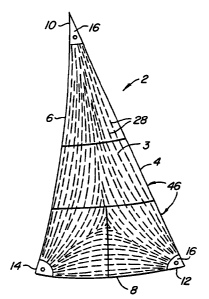
Fig. 1 illustrates a sail 2 made according to the invention. In this
embodiment sail 2 includes a sail body 3 and has three edges, Tuff 4, leech 6
and foot 8.
Sail 2 also has three comers, head 10 at the top, tack 12 at the lower forward
corner of the
sail at the intersection of Tuff 4 and foot 8, and clew 14 a the lower aft
corner of the sail at
the intersection of the leech and the foot. While sail 2 is typically a
molded, generally
triangular, three-dimensional sail, it could also be a two-dimensional sail
and could have
any of a variety of shapes. The finished sail 2 includes gussets 16 at head
10, tack 12 and
clew 14 and selvage 18 along Tuff 4, leech 6 and foot 8 to create the tinished
sail. A
process suitable for making sail body 3 and its construction will now be
discussed.
7
CA 02381282 2002-02-04
WO 01/17848 PCT/US00/24812
Fig. 2 illustrates a roll of adhesive-impregnated, uncured reinforced
material 20, also called a prepreg or a prepreg material. Material 20 is
typically made of
an uncured adhesive such as a copolyester resin, and a mesh or scrim 22 of
fibers or other
reinforcement elements. The mesh or scrim 22 will typically be unwoven but may
be
woven for increased tear resistance. Mesh or scrim 22 preferably includes a
set of first
reinforcement elements 24 which run parallel to one another along the length
of material
20 and a set of second, generally parallel reinforcement elements 26 which are
arranged
transversely to, typically perpendicular to, reinforcement elements 28.
Reinforcement
elements 24, 26 can be made from a variety of materials such as monofilament
material,
multifiber yarns made of, for example, carbon fiber, aramid fiber, polyester
fiber or fiber
sold under the trademarks PBOO, Pentex~ or Spectra~. Reinforcement elements
may
be, for example, cylindrical or flattened in cross-section and may be made of
twisted or
untwisted fibers. Reinforcement elements 24 are typically, but need not be,
the fibers used
to be generally aligned with the expected load lines 28 of sail 2.
In one embodiment, first and second reinforcement elements 24, 26 are
made of 500 denier unrivisted multifiber yarns and twisted multifiber yarns,
respectively.
Second reinforcement elements 26 are preferably twisted multifiber yarns for
increased
tear resistance. The spacing between first reinforcement elements 24 is, in
one
embodiment, about 3mm and the spacing between second reinforcements elements
is
- about l Omm. However, the first and second reinforcement elements 24, 26
could be
made of different materials and could be made with the same or different
diameters.
Also, the reinforcement elements could have equal or unequal lateral spacing
as well.
The choice of reinforcement elements 24, 26, their orientation and their
spacing will be
determined in large pan by the expected loading of sail 2.
?5 Material 20 is cut into sectors 30, 31 of prepreg material 20 of various
shapes and sizes, but typically triangular and quadrilateral, as suggested in
Fig. 2. Fig. 3
illustrates arranging triangular sectors 30 with their edges slightly
overlapping on to a
first, imperforate film 3?, film 32 typically made of PET, polyester film or
other materials
such as Kapton~ polyimide film made by Dupont. Each sector 30, 31 has a length
34 and
a width 36. the average length being substantially, typically at least about
three to ten
times, and more preferably at least about five times, the average width.
First,
longitudinally-extending reinforcement elements 24 are typically parallel to
length 34.
Pieces 30, 31 are sized. cut and arranged so that reinforcement elements.
typically first
reinforcement elements 24, will generally parallel expected load lines 28 when
sail 2 is
CA 02381282 2002-02-04
WO 01/17848 PCT/LTS00/24812
assembled. Fig. 4 illustrates a double layer of triangular sectors 30 with the
upper layer
38 not extending over the same surface area as the lower layer 40. Fig. 5
illustrates
overlapping of quadrilateral sectors 31 with the most extensive overlapping
taking place
at the lower left corner 41 to correspond to the concentration of expected
load lines 28 at
that region. When making multiple-layer sections. the sectors may be butt
joined
together within each layer to help create a smoother finished product. Of
course other
arrangements, sizes and shapes of sectors could also be used.
Fig. 6 illustrates capturing sectors 30 between first film 32 and a second
film 42. Pieces 30, 31 of reinforced material 20, first film 32 and second
film 42 may be
laminated in any of a variety of conventional or unconventional fashions. If
desired.
additional adhesives may be used between films 32, 42. Also, reinforced
material 20 may
be made without any adhesive so that all the adhesive is applied as a separate
step prior to
lamination. After lamination, the combination of sectors 30,31, films 32, 42
and the
adhesive bonding the layers constitute an uncut sail section 44, typically
generally
rectangular in shape. Uncut sail section 44 is then cut to the appropriate
shape to create a
sail section 46 as shown in Fig. 7. Sail body 3, in this embodiment, is made
by
assembling, typically broad seaming, four different sail sections 46 together
along their
adjacent edges 47. In addition to triangular sail section 46, sail 2 is also
made from three
different quadrilateral sail sections 46A, 46B and 46C. By comparing expected
load lines
on sail 1 with the suggested orientations of the reinforcement elements 24,
26. in
particular the longitudinally-extending the reinforcement elements 24, it is
seen that the
reinforcement elements are generally aligned with the expected load lines.
Uncut sail sections 44 may be either flat laminated sections or they may be
molded, three dimensional sail sections. Figs. 8, 8A and 8B illustrate one
method for
transforming the stack of sectors 30 of prepreg material 20 between films 32
and 42,
termed a material stack 64, into uncut sail section 44.
Material stack 64 is positioned between upper and lower flexible pressure
sheets 66, 68 as shown in Fig. 8. Pressure sheets 66. 68 are preferably made
of a flexible.
elastomeric material, such as silicone, which provides high-fizction surfaces
touching
films sides 32, 42 of material stack 6=1. L:pper and lower tlexibie pressure
sheets 66, 68
are circumscribed by upper and lower rectangular frames 70, 7 2. Frames 70, 72
are
mounted to upper and lower enclosure members 74, 76. Each enclosure member
7=1. 76 is
a generally three-sided enclosure member with open ends 78. 80. Upper and
lower
enclosure members 7-1. 76 catryina frames 70. 7 2 and flexible pressure sheets
66, 68
9
CA 02381282 2002-02-04
WO 01/17848 PCT/US00/24812
therewith. are then brought together as shown in Fig. 8A. A partial vacuum is
then
created within a lamination interior 82 formed between sheets 66, 68 using
vacuum
pump 83, thus creating a positive lamination pressure suggested by arrows 84
in Fig. 8A.
First and second end enclosure members 86, 88 are then mounted over the open
ends 78,
80 of upper and lower enclosure member 74, 76 to create a sealed enclosure 90.
First and second end enclosure members 86, 88 each include a fan 92 and
an electric heater element 94. Fans 92 cause air or other fluids, such as oil,
within
enclosure 90 to be circulated around and over the outer surfaces 96, 98 of
flexible
pressure sheets 66, 68. This ensures that flexible pressure sheets 66, 68 and
material
stack 64 thereberiveen are quickly and uniformly heated from both sides.
Because the
entire outer surfaces 96, 98 can be heated in this way, the entire material
stack 64 is
heated during the entire lamination process. This helps to ensure proper
lamination.
A$er a sufficient heating period, the interior 100 of enclosure 90 can be
vented to the
atmosphere and cooled with or without the use of fans 92 or additional fans.
After being
properly cooled, uncut sail section 44 is removed from between pressure sheets
66, 68.
Figs. 8, 8A and 8B illustrate the perforated nature of mold element 50
contacting outer surface 98 of lower flexible pressure sheet 68. In the
preferred
embodiment, perforated mold element 50 is made up of a number of relatively
thin
vertically-oriented members 104 oriented parallel to one another with
substantial gaps
therebetween to permit the relatively free access to the heated fluid to lower
surface 98.
Preferably, no more than about 20%, and more preferably no more than about 5%,
of that
portion of lower surface 98 which is coextensive with material stack 64 is
covered or
effectively obstructed by perforated mold element 50. Instead of verticallv-
oriented
members 104, perforated mold element ~0 could be made of, for example,
honeycomb
with vertically-oriented openings. Many dead spaces could be created within
the
vertically-extending honeycomb channels. thus substantially hindering heat
flow to large
portions of lower surface 98. This can be remedied by, for example, chancing
the air
flow direction so the air is directed into the honeycomb channels. minimizing
the height
of the honeycomb, and providing air flow escape channels in the honeycomb near
surface 98. Other shapes and configurations for perforated mold element ~0 can
also be
used.
Preferably the heated fluid within interior 100, which may be a gas or a
liquid, is in direct thermal contact with upper and lower surfaces 96, 98.
However, in
some circumstances an interposing surface could be created between the heated
fluid and
CA 02381282 2002-02-04
WO 01/17848 PCT/ITS00/24812
surfaces 96, 98. So long as such interposing surfaces do not create a
significant heat
barrier, the heated fluid will remain in effective thermal contact with outer
surfaces 96. 98
of pressure sheets 66, 68.
Vloditication and variation can be made to the disclosed embodiments
without departing izom the subject of the invention defined by the following
claims. For
example. first and second films 32, 42 may be made of the same or different
materials.
One or both films 32. 42 may not be imperforate. Section 46 may be joined by
other than
the broadseaming along adjacent edges 47, such as by conventional straight
seaming or
gluing techniques .
Any and all patents, patent applications and printed publications referred
to above are incorporated by reference.
11