Note: Descriptions are shown in the official language in which they were submitted.
CA 02381331 2009-05-13
29450-2
DISCHARGE ELECTRODE AND PHOTOCATALYSIS APPARATUS
BACKGROUND OF THE INVENTION
1. Field of the Invention
The present invention relates to a three-dimensional discharge electrode that
effectively and stably discharges, and to a photocatalysis apparatus employing
the three-
dimensional discharge electrode and a photocatalyst that becomes active when
irradiated
with light (ultraviolet rays) emitted from the electrode and removes hazardous
substances.
2. Description of the Related Art
It is well known that hazardous substances such as dioxins and NOx contained
in
the atmosphere or water cause environmental pollutions. To effectively remove
the
hazardous substances, various studies have energetically been made. There are
hazardous
substances that cause problems in closed spaces, such as putrid gas like
ethylene gas in
refrigerators, sick-house-syndrome causing chemicals like formaldehyde,
toluene, xylene,
and aradichlorobenzene in houses, and tobacco fumes in rooms or cabins.
To remove such hazardous substances, discharge apparatuses using electric
discharge and photocatalysis apparatuses using photocatalysts have been
developed.
Figure 1 shows a photocatalysis apparatus 101 according to a related art.
The photocatalysis apparatus 101 has a casing 102, a photocatalyst 103
carrying
titanium oxide (Ti02) and housed in the casing 102, a pair of thin-film
electrodes 104
arranged on each side of the photocatalyst 103, and a high-voltage power
source 105 to
apply a high voltage to the electrodes 104. Receiving the high voltage, the
electrodes 104
discharge. The discharge produces light (ultraviolet rays) to activate the
titanium oxide of
the photocatalyst 103. The activated photocatalyst 103 removes hazardous
substances
from incoming gas. When activated with ultraviolet rays, the photocatalyst 103
produces
hydroxy radicals (=OH) and super-oxide anions (=O2-). The hydroxy radicals are
strongly
-1-
CA 02381331 2002-04-09
oxidative to dissociate the molecular. The apparatus 101 uses the oxidizing
power of the
hydroxy radicals, to chemically remove hazardous substances.
This related art has some problems. The electrodes 104 are made of thin films
and are vulnerable to corrosive substances such as hydrogen sulfide, sulfurous
acid, nitrous
acid, chlorine, and ammonia among hazardous substances to remove.
Once the electrodes 104 corrode due to such corrosive substances, the corroded
part carries out no discharge, and therefore, the electrodes 104 unevenly
discharge. If the
corrosion develops further, the electrodes 104 will become partly
nonconductive to worsen
the uneven discharge. Then, the photocatalyst 103 will unevenly be activated
to provide
insufficient catalytic performance.
The thin-film electrodes 104 are unstable when installed. The electrodes 104
must be kept in parallel with each other to maintain the effect and efficiency
of the
photocatalyst 103. The electrodes 104 made of thin films easily shift, deform,
or break if
installed improperly or if exposed to excessive conditions such as a high flow
rate of
hazardous substances or a large amount of dust. If such trouble occurs, the
electrodes 104
will emit insufficient ultraviolet rays for the photocatalyst 103.
SUMMARY OF THE INVENTION
To solve these problems, the present invention provides a photocatalysis
apparatus
employing three-dimensional discharge electrodes that effectively and stably
discharge and
a photocatalyst that is activated by light generated by discharge of the
discharge electrodes
and efficiently and stably removes hazardous substances.
According to a first aspect of the present invention, a three-dimensional
discharge
electrode has an electrode body and a conductive frame. The electrode body
consists of
cells made of a conductive foil and has front, back, and side faces. The front
and back
faces are separated from each other by a predetermined distance and have a
shape selected
from a group including a honeycomb, a lattice, and a mesh. The conductive
frame covers
the side faces of the electrode body.
According to a second aspect of the present invention, a photocatalysis
apparatus
includes a photocatalyst module and a pair of discharge electrodes sandwiching
the
photocatalyst module. The photocatalyst module has a photocatalyst and a three-
dimensional ceramic mesh base carrying the photocatalyst. At least one of the
discharge
-2-
CA 02381331 2009-05-13
29450-2
electrodes is a three-dimensional discharge electrode having an electrode body
and a conductive frame. The electrode body consists of cells made of a
conductive foil and has front, back, and side faces. The front and back faces
are
separated from each other by a predetermined distance and have a shape
selected from a group including a honeycomb, a lattice, and a mesh. The
conductive frame covers the side faces of the electrode body.
According to a third aspect of the present invention, a photocatalysis
apparatus includes a plurality of unit structures each having a photocatalyst
module and a pair of discharge electrodes sandwiching the photocatalyst
module.
The photocatalyst module includes a photocatalyst and a three-dimensional
ceramic mesh base carrying the photocatalyst. At least one of the discharge
electrodes is a three-dimensional discharge electrode having an electrode body
and a conductive frame. The electrode body consists of cells made of a
conductive foil and has front, back, and side faces. The front and back faces
are
separated from each other by a predetermined distance and have a shape
selected from a group including a honeycomb, a lattice, and a mesh. The
conductive frame covers the side faces of the electrode body.
According to a fourth aspect of the present invention, there is
provided a three-dimensional discharge electrode comprising: an electrode body
consisting of cells made of a conductive foil, the electrode body having
front, back,
and side faces, the front and back faces being separated from each other by a
predetermined distance and having a shape consisting of a honeycomb, a
lattice,
or a mesh; and a conductive frame covering the side faces of the electrode
body;
wherein: the size of each of the cells is 5 mm at the minimum and the
thickness of
the foil is 1 mm at the maximum.
According to a fifth aspect of the present invention, there is provided
a photocatalysis apparatus comprising: a photocatalyst module including a
photocatalyst and a three-dimensional ceramic mesh base carrying the
photocatalyst; and a pair of discharge electrodes sandwiching the
photocatalyst
module, at least one of the discharge electrodes being a three-dimensional
discharge electrode according to the above fourth aspect.
-3-
CA 02381331 2009-05-13
29450-2
According to a sixth aspect of the present invention, there is
provided a photocatalysis apparatus comprising: a plurality of unit structures
each
having a photocatalyst module and a pair of discharge electrodes sandwiching
the
photocatalyst module, the photocatalyst module including a photocatalyst and a
three-dimensional ceramic mesh base carrying the photocatalyst, at least one
of
the discharge electrodes being a three-dimensional discharge electrode
according
to the above fourth aspect.
According to a seventh aspect of the present invention, there is
provided a photocatalysis apparatus comprising: a photocatalyst module
including
a photocatalyst and a three-dimensional ceramic mesh base carrying the
photocatalyst; and a pair of discharge electrodes sandwiching the
photocatalyst
module, characterized in that: one of the discharge electrodes is a three-
dimensional discharge electrode comprising an electrode body consisting of
cells
made of a conductive foil, the electrode body having front, back, and side
faces,
the front and back faces being separated from each other by a predetermined
distance and having the shape of a honeycomb, and a conductive frame covering
the side faces of the electrode body, the size of each of the cells is 5 mm at
the
minimum and the thickness of the foil is 1 mm at the maximum, another of the
discharge electrodes is a three-dimensional discharge electrode comprising an
electrode body consisting of cells made of a conductive foil, the electrode
body
having front, back, and side faces, the front and back faces being separated
from
each other by a predetermined distance and having the shape of a lattice; and
a
conductive frame covering the side faces of the electrode body, the size of
each of
the cells is 10 mm.
-3a-
CA 02381331 2009-05-13
29450-2
BRIEF DESCRIPTION OF THE DRAWINGS
Figure 1 shows a photocatalysis apparatus according to a related art;
Figs. 2 and 3 show a photocatalysis apparatus according to a first embodiment
of
the present invention;
Fig. 4 shows a photocatalysis apparatus according to a second embodiment of
the
present invention;
Fig. 5 shows a photocatalysis apparatus according to a third embodiment of the
present invention;
Fig. 6 shows a photocatalysis apparatus according to a fourth embodiment of
the
present invention;
Fig. 7 shows a photocatalysis apparatus according to a fifth embodiment of the
present invention;
Fig. 8 shows a photocatalysis apparatus according to a sixth embodiment of the
present invention;
Fig. 9 is a graph showing light intensities from different electrode
structures;
Fig. 10 is a graph showing a distribution of light intensities from thin-film
-3b-
CA 02381331 2002-04-09
electrodes according to the related art;
Fig. 11 is a graph showing a distribution of light intensities from honeycomb
electrodes according to the present invention;
Fig. 12 explains the cell size and foil thickness of a honeycomb electrode
according to the present invention;
Fig. 13 is a graph showing a relationship between the cell size and intensity
of a
honeycomb electrode;
Fig. 14 is a graph showing a relationship between the foil thickness and
intensity
of a honeycomb electrode; and
Fig. 15 is a graph showing a relationship between photocatalyst-module
thicknesses and light intensities.
DETAILED DESCRIPTION OF EMBODIMENTS
Various embodiments of the present invention will be described with reference
to
the accompanying drawings.
(First embodiment)
Figures 2 and 3 show a photocatalysis apparatus according to the first
embodiment of the present invention.
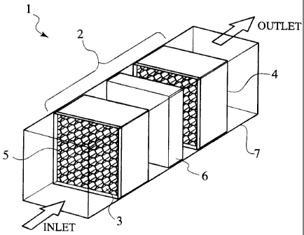
In Fig. 2, the photocatalysis apparatus 1 (1A in Fig. 3) has a unit structure
2 and a
casing 7 housing the unit structure 2. The casing 7 is in a pipe shape and has
an inlet and
an outlet to pass gas containing hazardous substances therethrough. The unit
structure 2
includes a pair of honeycomb electrodes 5 and a photocatalyst module 6
sandwiched
between the electrodes 5. The electrodes 5 are connected to a high-voltage
power source
8 (Fig. 3).
Each electrode 5 is made of an electrode body 3 and a conductive frame 4. The
electrode body 3 is a three-dimensional structure formed from cells made of a
conductive
foil. The electrode body 3 has front, back, and side faces in which the front
and back
faces are separated from each other by a predetermined distance and have a
honeycomb
shape, to pass gas containing hazardous substances through the electrode body
3. The
side faces of the electrode body 3 are covered with the conductive frame 4.
In Fig. 3, the honeycomb electrodes 5 receive power from the power source 8
and
discharge. The electrode body 3 and conductive frame 4 of each electrode 5 are
made
-4-
CA 02381331 2002-04-09
from stainless steel that is resistive to corrosive substances such as
hydrogen sulfide.
When discharging, the electrodes 5 emit light that includes ultraviolet rays
(having a wavelength of 185 nm). The ultraviolet rays produce ozone from
oxygen
contained in the atmosphere. The ozone has deodorizing, decolorizing,
disinfecting, and
sterilizing functions and is capable of decomposing and removing hazardous
substances
such as hydrogen sulfide and ammonia. At the same time, the strong oxidizing
effect of
the ozone oxidizes metal electrodes.
Corrosive substances such as hydrogen sulfide, sulfurous acid, nitrous acid,
chlorine, and ammonia also corrode metal electrodes. The electrodes 5,
therefore, must
be made of or coated with corrosion resistive material.
It is preferable to make the electrode body 3 and conductive frame 4 of each
electrode 5 from stainless steel, coated aluminum, coated copper, Hastelloy,
platinum, gold,
or any other corrosion resistive metal or alloy.
The honeycomb cells of the electrode body 3 may each have a size of 5 mm or
greater. The foil that forms the electrode body 3 may have a thickness of 1 mm
or thinner,
preferably, in the range of 0.1 to 0.2 mm. The reason of this will be
explained later.
The photocatalyst module 6 includes a three-dimensional ceramic mesh base
whose surface carries semiconductor particles such as Ti02 particles that
provide a
photocatalysis function. The thickness of the photocatalyst module 6 must be
15 mm or
thinner. The reason of this will be explained later.
There are various semiconductor particles that provide the photocatalysis
function
and are applicable to the photocatalyst module 6. A typical semiconductor
providing the
photocatalysis function is titanium oxide (Ti02) of anatase, rutile, or
brookite type. Other
semiconductors that provide the photocatalysis function are metal oxide
semiconductors
such as SrTiO3, ZnO, BaTiO3, V205, and SnOz, element semiconductors such as
Si, and
compound semiconductors such as GaAs, CdS, and ZnS.
The power source 8 to supply power to the honeycomb electrodes 5 is selected
according to the installation conditions of the photocatalysis apparatus 1
(1A). The power
source 8 may be a DC power source, a pulse power source to provide short
pulses having a
duty factor of 0.5 or lower, or an AC power source operating at a frequency of
10 kHz or
higher. The power source 8 may be provided with a function of superposing a DC
bias of
50% to 90% of a peak value, or a function of intermittent operation.
-5-
CA 02381331 2002-04-09
If the power source 8 is a DC power source, it will realize a simple structure
to
reduce cost, and low discharge noise to secure a quiet operation.
If the power source 8 is a pulse power source, it will realize high energy,
compactness, a simple structure, and cost reduction. The pulse power source
easily
provides large discharge energy, and therefore, is appropriate for low-cost,
middle-size
photocatalysis apparatuses.
If the power source 8 is a high-frequency AC power source operating at 10 kHz
or
higher, discharge energy can be increased in proportion to the operating
frequency thereof.
Accordingly, the high-frequency AC power source is suitable for photocatalysis
apparatuses that need large energy to carry out a deodorizing operation in
large scale, or to
process highly concentrated substances.
If the power source 8 is combined with a superposed DC bias, it can reduce a
pulse voltage and realize compactness. In addition, superposing a DC bias
stabilizes the
number of incidental atoms that cause discharge, to equalize spark transition
voltage and
secure a stable operation.
If the power source 8 is a pulse power source or an AC power source, the
discharge input energy per pulse or period of the photocatalysis apparatus 1
(1A) is
uniquely determined from gas composition and discharge parameters related to
an
electrode shape and an electrode-to-electrode distance.
Power applied from the power source 8 is expressed as follows:
Exr(W)
where E (J) is discharge input energy per pulse or period and r (pps or Hz) is
a frequency.
To maintain this power irrespective of frequencies, an intermittent operation
is needed.
The ratio of operation to non-operation, i.e., a modulation factor of the
intermittent operation is expressed as follows:
P / (E x F)
where P is the applied power, E is applied energy per pulse or period, and F
is a frequency.
With applied power of 10 (W), applied energy per pulse of 50 (mJ), and
frequency
of 20 (kHz), the modulation factor is as follows:
10/(50x 10-3x20x 10) =0.01
In this case, an intermittent operation of 10 ms per second is needed.
The intermittent operation is not lirnited to the 10-ms operation per second.
For
-6-
CA 02381331 2002-04-09
example, it may be a 20-ms operation per two seconds, or two 5-ms operations
per second.
If the power source 8 is a DC power source, power applied from the power
source
8 is uniquely determined according to discharge parameters. The intermittent
operation is
effective to lower power consumption without fluctuating voltage.
Operation of the photocatalysis apparatus of Figs. 2 and 3 will be explained.
The
power source 8 applies a high voltage to the honeycomb electrodes 5. The
electrodes 5
start to discharge to emit light (ultraviolet rays), which uniformly
irradiates the
photocatalyst module 6 to activate the photocatalyst of the module 6. The
activated
photocatalyst produces hydroxy radicals (-OH) that are chemically reactive. At
the same
time, the discharge light produces ozone. The hydroxy radicals and ozone
chemically
react with hazardous substances entering the unit structure 2 and decompose
and remove
the hazardous substances.
According to the first embodiment, the side faces of each electrode 5 are
covered
with the conductive frame 4 and the electrode 5 has a width, to improve
corrosion
resistivity compared with the thin-film electrodes of the related art.
The honeycomb structure of each electrode 5 secures mechanical accuracy and
strength, to keep a fixed distance between the adjacent electrodes 5 for a
long time. As a
result, the electrodes 5 uniformly and effectively irradiate the photocatalyst
module 6 with
discharge light so that the module 6 may efficiently and stably show a
substance
decomposing function for a long time.
According to the first embodiment, ozone produced by discharge chemically
reacts with hazardous substances that have not been removed by the
photocatalyst module
6 and decomposes and removes them. Namely, the oxidizing power of ozone
improves
the decomposing efficiency of the photocatalysis apparatus.
If the power source 8 is a DC power source, the electrodes 5 have polarities.
In
this case, any one of the positive and negative electrodes may be on the inlet
side of the
photocatalysis apparatus, to provide the effect of the first embodiment.
(Second embodiment)
Figure 4 shows a photocatalysis apparatus 1B according to the second
embodiment of the present invention. The second embodiment employs a plurality
of
unit structures each being the unit structure 2 of Figs. 2 and 3.
The photocatalysis apparatus 1B has a plurality of (four in this example) unit
-7-
CA 02381331 2002-04-09
structures 2, a casing 7 accommodating the unit structures 2, and a high-
voltage power
source 8. Each unit structure 2 has a pair of honeycomb electrodes 5 and a
photocatalyst
module 6 sandwiched between the electrodes 5. The electrodes 5 are connected
to the
power source 8.
Two adjacent unit structures 2 share one electrode 5 so that each electrode 5
may
efficiently emit light toward the unit structures 2.
The configuration, material, etc., of the electrode 5, photocatalyst module 6,
semiconductor catalytic particles of the module 6, and power source 8 are
basically the
same as those of the first embodiment, and therefore, are not explained again.
Operation of the photocatalysis apparatus 1B will be explained. The power
source 8 applies a high voltage to the electrodes 5. The electrodes 5 start to
discharge and
emit light (ultraviolet rays). The light uniformly in:adiates the
photocatalyst modules 6
and activates the photocatalysts thereof. The activated photocatalysts produce
hydroxy
radicals (OH) that are chemically reactive. At the same time, the emitted
light produces
ozone. The hydroxy radicals and ozone chemically react with hazardous
substances
flowing through the unit structures 2, to thereby decompose and remove the
hazardous
substances.
According to the second embodiment, the honeycomb electrodes 5 show
corrosion resistance and mechanical accuracy and strength like the first
embodiment. The
concatenated four unit structures 2 provide decomposing capacity four times
greater than
the first embodiment.
The number of electrodes 5 of the second embodiment is greater than that of
the
first embodiment, to produce a larger amount of ozone to promote the
oxidization and
decomposition of hazardous substances.
(Third embodiment)
Figure 5 shows a photocatalysis apparatus 1C according to the third embodiment
of the present invention. The third embodiment is a combination of the
photocatalysis
apparatus of the first embodiment and an ozonolysis catalyst 9.
The photocatalysis apparatus 1C has a unit structure 2, the ozonolysis
catalyst 9, a
casing 7 housing the unit structure 2 and ozonolysis catalyst 9, and a high-
voltage power
source 8.
The unit structure 2 includes a pair of honeycomb electrodes 5 and a
photocatalyst
-8-
CA 02381331 2002-04-09
module 6 sandwiched between the electrodes 5. The electrodes 5 are connected
to the
power source 8. The ozonolysis catalyst 9 is arranged downstream from the unit
structure
2 in a gas flowing direction.
The configuration, material, etc., of the electrode 5, photocatalyst module 6,
semiconductor catalytic particles of the module 6, and power source 8 are
basically the
same as those of the first embodiment, and therefore, are not explained again.
According to the first and second embodiments mentioned above, discharge light
produces ozone to oxidize, decompose, and remove hazardous substances, and
ozone that
has not reacted with hazardous substances is discharged as it is. The ozone
discharged
into the atmosphere is hazardous to human bodies, and therefore, must be
decomposed.
The ozonolysis catalyst 9 decomposes such unreacted ozone into innocuous
oxygen.
The ozonolysis catalyst 9 may employ an optional ozonolysis method depending
on conditions. For example, it may employ an activated carbon
absorption/decomposition method, a heating decomposition method, a contact
decomposition method, a water washing method, a chemical washing method
(alkali
washing method), or a chemical reduction method.
Operation of the photocatalysis apparatus 1C will be explained. The power
source 8 applies a high voltage to the electrodes 5. The electrodes 5 start to
discharge and
emit light (ultraviolet rays). The light uniformly irradiates the
photocatalyst module 6
and activates the photocatalyst thereof. The activated photocatalyst produces
hydroxy
radicals (-OH) that are chemically reactive. At the same time, the emitted
light produces
ozone. The hydroxy radicals and ozone chemically react with hazardous
substances
flowing through the unit structure 2, to thereby decompose and remove the
hazardous
substances. The ozonolysis catalyst 9 decomposes unreacted ozone into harmless
oxygen.
The third embodiment provides the same hazardous substance decomposing
performance as the first embodiment. In addition, the ozonolysis catalyst 9
decomposes
ozone that has not reacted with hazardous substances, to prevent hazardous
ozone from
spreading into the atmosphere.
The third embodiment arranges one ozonolysis catalyst 9 on the downstream side
of the unit structure 2. An optional number of ozonolysis catalysts may be
arranged at
optional locations in the photocatalysis apparatus if they properly remove
ozone.
(Fourth embodiment)
-9-
CA 02381331 2002-04-09
Figure 6 shows a photocatalysis apparatus 1D according to the fourth
embodiment
of the present invention. This embodiment is a combination of the
photocatalysis
apparatus 1B of Fig. 4 and the ozonolysis catalyst 9 of Fig. 5.
The photocatalysis apparatus 1D has four unit structures 2, an ozonolysis
catalyst
9, a casing 7 housing the unit structures 2 and ozonolysis catalyst 9, and a
high-voltage
power source 8. Each unit structure 2 has a pair of honeycomb electrodes 5 and
a
photocatalyst module 6 sandwiched between the electrodes 5. The electrodes 5
are
connected to the power source 8. The ozonolysis catalyst 9 is arranged
downstream from
the unit structures 2 in a gas flowing direction.
The configuration, material, etc., of the electrode 5, photocatalyst module 6,
semiconductor catalytic particles of the module 6, and power source 8 are
basically the
same as those of the second embodiment, and therefore, are not explained
again.
Operation of the photocatalysis apparatus 1D will be explained. The power
source 8 applies a high voltage to the electrodes 5. The electrodes 5 start to
discharge and
emit light (ultraviolet rays). The light uniformly irradiates the
photocatalyst modules 6
and activates the photocatalysts thereof. The activated photocatalysts produce
hydroxy
radicals (-OH) that are chemically reactive. At the same time, the emitted
light produces
ozone. The hydroxy radicals and ozone chemically react with hazardous
substances
flowing through the unit structures 2, to thereby decompose and remove the
hazardous
substances. The ozonolysis catalyst 9 decomposes unreacted ozone into harmless
oxygen.
The fourth embodiment provides the same hazardous substance decomposing
performance as the second embodiment. In addition, the ozonolysis catalyst 9
decomposes ozone that has not reacted with hazardous substances, to prevent
hazardous
ozone from spreading into the atmosphere.
The fourth embodiment arranges one ozonolysis catalyst 9 on the downstream
side of the unit structures 2. An optional number of ozonolysis catalysts may
be arranged
at optional locations in the photocatalysis apparatus if they properly remove
ozone.
(Fifth embodiment)
Figure 7 shows a photocatalysis apparatus 1E according to the fifth embodiment
of the present invention. This embodiment is a combination of the
photocatalysis
apparatus of Figs. 2 and 3 and a fan 10.
The photocatalysis apparatus 1E has a unit structure 2, the fan 10, a casing 7
-10-
CA 02381331 2002-04-09
housing the unit structure 2 and fan 10, and a high-voltage power source 8.
The unit structure 2 includes a pair of honeycomb electrodes 5 and a
photocatalyst
module 6 sandwiched between the electrodes 5. The electrodes 5 are connected
to the
power source 8. The fan 10 is arranged at an inlet of the photocatalysis
apparatus 1E.
The configuration, material, etc., of the electrode 5, photocatalyst module 6,
semiconductor catalytic particles of the module 6, and power source 8 are
basically the
same as those of the first embodiment, and therefore, are not explained again.
The fan 10 is used when a flow rate of gas containing hazardous substances
passing through the apparatus 1E is slow, or when the gas must forcibly be
circulated.
When gas is circulated by free convection, the gas circulation may stop
depending on
conditions. In this case, the fan 10 is used to forcibly circulate the gas or
secure a given
flow rate of the gas.
The fan 10 may be arranged at the inlet and/or outlet of the apparatus 1E, or
it
may be arranged at an optional position. If a plurality of unit structures 2
are employed,
the fan 10 may be arranged between every two adjacent unit structures 2. The
fan 10 may
be arranged between one of the electrodes 5 and the photocatalyst module 6 of
the unit
structure 2, or in front of an ozonolysis catalyst.
Operation of the photocatalysis apparatus 1E will be explained. The fan 10
forcibly feeds gas containing hazardous substances into the casing 7. The
power source 8
applies a high voltage to the electrodes 5. The electrodes 5 start to
discharge and emit
light (ultraviolet rays). The light uniformly irradiates the photocatalyst
module 6 and
activates the photocatalyst thereof. The activated photocatalyst produces
hydroxy
radicals (=OH) that are chemically reactive. At the same time, the emitted
light produces
ozone. The hydroxy radicals and ozone chemically react with hazardous
substances
flowing through the unit structure 2, to thereby decompose and remove the
hazardous
substances.
The fifth embodiment provides the same hazardous substance decomposing
performance as the first embodiment. In addition, the fan 10 secures a given
flow rate of
gas passing through the apparatus IE, to maintain the substance decomposing
capacity of
the apparatus 1E for a long time.
(Sixth embodiment)
Figure 8 shows a photocatalysis apparatus 1F according to the sixth embodiment
-11-
CA 02381331 2002-04-09
of the present invention. This embodiment is a combination of the
photocatalysis
apparatus 1E of the fifth embodiment and a filter 11.
The photocatalysis apparatus 1F has a unit structure 2, a fan 10, the filter
11, a
casing 7 housing the unit structure 2, fan 10, and filter 11, and a high-
voltage power source
8.
The unit structure 2 includes a pair of honeycomb electrodes 5 and a
photocatalyst
module 6 sandwiched between the electrodes 5. The electrodes 5 are connected
to the
power source 8. The fan 10 is arranged at an inlet of the apparatus 1F. The
filter 11 is
arranged on the inlet side of the fan 10.
The configuration, material, etc., of the electrode 5, photocatalyst module 6,
semiconductor catalytic particles of the module 6, and power source 8 are
basically the
same as those of the first embodiment, and therefore, are not explained again.
When the apparatus 1F is used in an environment containing a lot of dust, the
photocatalyst module 6 and electrodes 5 may be clogged or broken. The filter
11
removes dust and substances that may hinder the performance and functions of
the
electrodes 5 and module 6, to maintain the substance decomposing performance
of the
apparatus 1F.
Operation of the photocatalysis apparatus 1F will be explained. The filter 11
removes dust from gas containing hazardous substances. The fan 10 forcibly
feed the
dust removed gas into the casing 7. The power source 8 applies a high voltage
to the
electrodes 5. Discharge start and emit light (ultraviolet rays). The light
uniformly
irradiates the photocatalyst module 6 and activates the photocatalyst thereof.
The
activated photocatalyst produces hydroxy radicals (=OH) that are chemically
reactive. At
the same time, the emitted light produces ozone. The hydroxy radicals and
ozone
chemically react with hazardous substances flowing through the unit structure
2, to thereby
decompose and remove the hazardous substances.
The sixth embodiment provides the same hazardous substance decomposing
performance as the first embodiment. In addition, the filter 11 removes dust
and other
substances obstructive to the photocatalysis apparatus 1F, to maintain the
substance
decomposing capacity of the apparatus 1F for a long time.
(Other embodiments)
The embodiments mentioned above employ honeycomb electrodes. The present
-12-
CA 02381331 2002-04-09
invention allows other embodiments.
For example, one of the electrodes 5 of the unit structure 2 may be a thin-
film,
mesh or thin-wire electrode. The unit structures 2 each having such different
electrodes
may be concatenated so that the electrodes of different shapes are alternated.
The present invention may employ not only the honeycomb electrodes but also
lattice electrodes and mesh electrodes. According to the present invention, a
pair of
positive and negative electrodes may be the same electrodes or different
electrodes. For
example, an electrode pair may consist of a honeycomb electrode and a lattice
electrode.
According to the present invention, a pair of positive and negative electrodes
may
have different cell sizes. For example, an electrode pair may consist of a
honeycomb
electrode having a cell size of 5 mm and a lattice electrode having a cell
size of 10 mm.
In addition to the filter 11 of Fig. 8, the photocatalysis apparatus according
to the
present invention may employ catalysts and absorbents. These catalysts and
absorbents
are used to remove specific substances, so that the photocatalysis apparatus
may remove
the remnants. Alternatively, the photocatalysis apparatus removes specific
substances, so
that the catalysts and absorbents may remove the remnants. Such catalysts and
absorbents improve the performance of the photocatalysis apparatus.
The photocatalysis apparatus of any one of Figs. 3 and 4 is applicable to
process
industrial exhaust gas and clean air. The photocatalysis apparatus of any one
of Figs. 5
and 6 may be incorporated in room air conditioners, car air conditioners,
vacuum cleaners,
and refrigerators. The photocatalysis apparatus of Fig. 7 may be incorporated
in
refrigerators that employ natural convection. The photocatalysis apparatus of
Fig. 8 is
applicable to room air cleaners (in combination with the ozonolysis catalyst
of Fig. 5) and
smoke separators.
(Tests on honeycomb electrodes)
Tests were carried out to examine the characteristics of discharge electrodes,
in
particular, honeycomb electrodes in the unit structure 2 of Fig. 2. Results of
the tests will
be explained.
(Performance comparison between present invention and related arts)
(1) Intensity differences due to electrode stnictures
To activate and improve a substance decomposing function, a photocatalyst
needs
strong discharge light (ultraviolet rays having a wavelength of 380 nm or
shorter). To
-13-
__.
CA 02381331 2002-04-09
produce strong discharge light, a strong electric field is needed. The
electric field is
dependent on the shapes of discharge electrodes.
Figure 9 is a graph showing light intensities from thin-film mesh electrodes
according to a related art, thin-film lattice electrodes according to a
related art, and the
honeycomb electrodes of the present invention. These electrodes have the same
area and
are provided with the same power source (the same input energy). The honeycomb
electrodes of the present invention generate discharge light 1.5 to 2 times
stronger than the
electrodes of the related arts. This means that the present invention is
capable of realizing
substance decomposing capacity 1.5 to 2 times higher than the related arts
with the same
power consumption.
(2) Intensity distribution differences due to electrode structures
Figure 10 is a graph showing an intensity distribution of light from a thin-
film
electrode according to a related art, and Fig. 11 is a graph showing an
intensity distribution
of light from the honeycomb electrode of the present invention with the same
power source
(the same input energy) and the same electrode area.
The related art of Fig. 1.0 provides intensities sufficient to activate a
photocatalyst
only along the periphery of the electrode. The related art provides
insufficient intensities
at the central area of the electrode. Such intensity fluctuations are improper
to uniformly
activate a photocatalyst.
In Fig. 11, the present invention provides uniform intensities all over the
electrode.
Compared with the related art, the present invention stably activates a
photocatalyst and
realizes high decomposing performance.
(Electrode cell shape)
(1) Performance and cell size
The honeycomb electrode of the present invention is composed of honeycomb
cells. Figure 12 explains a cell size 12 of each honeycomb cell. The cell size
12
determines the intensity of light produced by electrode discharge. Figure 13
is a graph
showing a relationship between the cell size: and intensity of the honeycomb
electrode.
When the cell size 12 exceeds 5 mm, the intensity of discharge light steeply
increases to
realize high decomposing performance.
(2) Performance and foil thickness
The honeycomb electrode of the present invention is made of a metal foil as
-14-
CA 02381331 2002-04-09
shown in Fig. 12. The thickness 13 of the metal foil determines the intensity
of light
produced by electrode discharge. Figure 14 is a graph showing a relationship
between the
foil thickness and discharge light intensity of the honeycomb electrode. When
the foil
thickness 13 is in the range of 0.1 to 0.2 mm, the intensity of discharge
light steeply
increases to realize high decomposing performance.
(Reaching distance of discharge light)
To fully exploit the deconiposing function of a photocatalyst, it is necessary
to
uniformly irradiate the photocatalyst with discharge light and make the light
penetrate the
photocatalyst to the bottom thereof. Figure 15 is a graph showing a
relationship between
distance (the thickness of the photocatalyst module 6) and intensity of
discharge light.
Generally, light intensity necessary to activate a photocatalyst is 10"6
W/cm2. As
is apparent in Fig. 15, part of the photocatalyst deeper than 15 mm receives
insufficient
light to activate the photocatalyst. Accordingly, the thickness of the
photocatalyst module
6 sandwiched between the three-dimensional electrodes 5 according to the
present
invention must be 15 mm or thinner, so that the module 6 may wholly show high
decomposing capacity.
As explained above, the honeycomb electrode according to the present invention
is three-dimensional and has side faces covered with a conductive frame, to
improve
corrosion resistance. The honeycomb electrode uniformly emits discharge light
for a long
time.
The electrode according to the present invention secures proper mechanical
accuracy and strength, to maintain a given distance to an adjacent electrode
for a long time.
The electrode of the present invention provides discharge light that uniformly
and
effectively irradiates a photocatalyst module, to thereby maintain high
decomposing
capacity for a long time.
The photocatalysis apparatus according to the present invention discharges to
emit
light while passing gas containing hazardous substances therethrough. The
emitted light
activates a photocatalyst arranged in the apparatus and produces hydroxy
radicals. On the
surface of the photocatalyst, the hydroxy radicals chemically react with the
hazardous
substances and remove the hazardous substances.
The photocatalysis apparatus of the present invention employing a plurality of
unit structures each having discharge electrodes and a photocatalyst module is
capable of
-15-
CA 02381331 2002-04-09
maintaining high decomposing capacity for a long time.
The photocatalysis apparatus according to the present invention produces ozone
in
addition to hydroxy radicals. The ozone reacts with hazardous substances on
the surfaces
of the photocatalyst module and electrodes, to surely remove hazardous
substances that
have not been removed by the photocatalyst module, thereby improving the
processing
efficiency of the apparatus.
The photocatalysis apparatus of the present invention employing an ozonolysis
catalyst decomposes ozone that has not been reacted with hazardous substances,
to thereby
prevent the hazardous ozone from spreading into the atmosphere.
The photocatalysis apparatus of the present invention employing a fan secures
a
given flow rate of gas in the apparatus, to maintain the decomposing capacity
of the
apparatus for a long time.
The photocatalysis apparatus of the present invention employing a filter
removes
substances obstructive to the apparatus in advance, to stabilize and secure
the decomposing
capacity of the apparatus for a long time.
The photocatalysis apparatus of the present invention employing a high-
frequency
AC power source that is intermittently operated efficiently reduces power
consumption.
Additional advantages and modifications of the present invention will readily
occur to those skilled in the art. Therefore, the present invention in its
broader aspects is
not limited to the specific details and representative embodiments shown and
described
herein. Accordingly, various modifications may be made without departing from
the
spirit or scope of the general inventive concept as defined by the appended
claims and their
equivalents.
-16-