Note: Descriptions are shown in the official language in which they were submitted.
CA 02381475 2002-02-11
WO 01/12307 PCT/FI00/00681
1
METHOD FOR THE LEACHING OF SOLID MATTER FROM SLUDGE
The present invention relates to a method for the leaching of solid matter
from a sludge with the aid of a gas containing oxygen, whereby the solid
matter of the sludge is recirculated in a tall reactor equipped with a central
pipe in the centre of the reactor and a double-action mixer located in the
vicinity of the lower edge of the central pipe. A flow is formed with the aid
of
the mixer which sucks the sludge from the central pipe downward, and a gas
to be conducted into the sludge in the bottom part of the reactor is dispersed
l0 in the form of small bubbles into the sludge outside the central pipe and
the
flow direction of the sludge is turned upwards in the outer casing of the
reactor.
In leaching of a sludge containing solid matter, such as for example metal
concentrate, it is important that the participatory oxygen in the leaching,
being introduced in the form of oxygen or gas containing oxygen, must firstly
dissolve into the solid-containing sludge, in order that the oxygen can
participate in the leaching reactions of the solid matter. A tall reactor is
used
for the improvement of the dissolution of the oxygen, whereupon, as
compared to normal atmospheric reactors, great hydrostatic pressure forms
at the bottom of the reactor (1.5 - 3.0 atm, i.e. 0.15 - 0.30 MPa), due to
which the oxygen dissolves well in the reaction solution and thereby
catalyses the dissolution of the solid matter.
In the prior art it is known for example US Pat. No. 4,648,973, wherein the
equipment concerns a reactor with a height many times greater than its
diameter, inside which is located a concentric pipe. The sludge is fed into
the upper part of the central pipe, as is the oxygen. For recirculation of the
sludge, the central pipe is equipped with a mixer suspended from the top
downwards, which pumps the sludge down the central pipe and the sludge
then passes up through the space between the reactor and the internal pipe.
CA 02381475 2006-11-09
2
The ratio between the diameters of the central pipe and outer pipe is between
0.4 and
0.85.
Now, the developed invention relates to a method for leaching of solid matter
from a
sludge, such as metal concentrate with the aid of oxygen-containing gas
whereby the
sludge is recirculated in a tall reactor. The height of the reactor is many
times greater
than its diameter and the reactor is equipped with a concentric central pipe
extending
to the bottom part, a mixer being located in the vicinity of the lower part of
the central
pipe and a feeding member for gas containing oxygen. The shaft of the mixer
extends
upwards from the bottom of the reactor. A sludge flow turning downwards is
achieved
with the aid of the mixer. The gas containing oxygen to be fed underneath the
mixer is
dispersed into the sludge in the form of small bubbles and at the same time
the flow
direction of the sludge is turned in the bottom part of the reactor to ascend
upwards.
Reactions between the solid matter-containing sludge and the oxygen-containing
gas
happen mainly either in the bottom part of the reactor or in a casing part
between the
reactor walls and the central pipe. The essential features of the present
invention are
laid out in the enclosed claims.
A particularly preferred aspect of the invention relates to a method for
leaching of
solid matter from a sludge of metal concentrate aided by a gas containing
oxygen,
comprising leaching the solid matter from the sludge in a tubular reactor,
with a
height at least two times greater than its diameter and which is equipped with
a
concentric central pipe and a double action mixer having upper blades and
lower
blades, forming a downward directed sludge flow in the central pipe with the
aid of
upper-curved blades of the mixer, the mixer being located upward from the
bottom of
the reactor in the immediate vicinity of the lower edge of the central pipe,
turning the
direction of sludge flow outside the central pipe in the bottom part of the
reactor to an
upward flow while feeding and dispersing an oxygen-containing gas into the
sludge in
the form of small bubbles to prevent solid matter in the sludge from settling
to the
bottom of the reactor.
As mentioned above, it is more particularly preferred to the method that the
mixer is
located in the immediate vicinity of the lower edge of the central pipe,
whereby the
cross-section area of the discharge orifice remaining between the central pipe
and the
CA 02381475 2006-11-09
2a
mixer is less than half the cross-section area of the central pipe, preferably
at most one
third of the cross-section area of the pipe. Thus the flow rate, from the
central pipe, of
the downward-flowing sludge increases at least twofold in comparison to the
flow rate
taking place in the central pipe. The nearer the mixer is located to the lower
edge of
the pipe, the better the suction building up to the central pipe. In practice
the limit is
set by the tolerances, which result from the wearing of the shaft and from the
flexibility and dimensioning of the other parts. At the aforementioned
CA 02381475 2002-02-11
WO 01/12307 PCT/FI00/00681
3
cross-sectional area ratio, such a flow rate is achieved that the
downward-directed solution flow is faster than the ascending rate of the gas
bubbles, and the upward flow rate of the solution in the annular casing of the
reactor is greater than the settling rate of the particles of the solid
matter.
The mixer used in the method according to the invention is of double-action,
it is formed of two parts having an essentially horizontal plate between them.
Curved blades are fixed above the horizontal plate which suck sludge
downward in the central pipe. The blades fixed underneath the horizontal
l0 plate form a straight-bladed turbine mixer. As the gas containing oxygen is
fed underneath the mixer installed in the bottom part of the reactor, the
lower
part of the mixer disperses the feed gas into very small bubbles, thus
assisting the dissolution of the gas into the sludge. As the gas is fed into
the
sludge at the bottom part of the reactor, the gas bubbles moving with the
sludge flow have as long a residence and reaction time in the sludge as
possible, before they reach the surface or descend with the flow to be
recirculated through the central pipe or are discharged through outlet means
in the upper part of the reactor.
The equipment for carrying out the method according to the invention is
explained in more detail with the aid of the enclosed figures, wherein
figure 1 shows a vertical section of the reactor,
in figure 2 a vertical section of the reactor is shown at the point of the
central
pipe and mixer, and
figure 3 shows a three-dimensional picture of the reactor mixer.
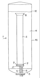
For the leaching of sludge containing solid matter, figure 1 shows a tubular
reactor 1, equipped with a concentric central pipe 2, which extends to the
bottom part of the reactor. The distance of the central pipe from the reactor
bottom is at range between 0.2 - 1.0 times the reactor diameter preferably
between 0.3 - 0.5. The surface area ratio between the central pipe and the
CA 02381475 2002-02-11
WO 01/12307 PCT/FI00/00681
4
casing of the reactor surrounding it is below 0.1. Upward from a reactor
bottom 3 is a mixer 5 supported by its shaft 4, and a feed member 6 for gas
containing oxygen. As the inlet of the mixer shaft is in the lower part of the
reactor, the shaft can be made to be as short and as sturdy as is possible.
5'
The mixer is concentric with the pipe 2 and is located in very close proximity
to a lower edge 7 of the central pipe. As seen in the figure, the central pipe
2
can be equipped at the upper and lower ends with conical extensions 8 and
9. According to the figure the mixer can also be placed partly inside the
l0 central pipe. The annular space between reactor walls 10 and central pipe 2
can be designated as a casing 11. When necessary the lower part of the
central pipe can be equipped with baffles (not illustrated). The sludge feed
to the reactor can be fed in a conventional manner for example to the central
pipe and the solution can be removed for example as overflow or the sludge
15 can be prefarble fed and discharged via its own means under a sludge
surface 12. The inlet and outlet means are not illustrated in more detail in
the figure.
As can be seen from figures 2 and 3, the mixer 5 comprises the mixer shaft
20 4, to which is fixed a horizontal plate 13, below which are attached
straight
lower blades 14 and above which are attached curved upper blades 15.
The horizontal plate of the mixer impedes the flow of sludge from above the
mixer to below it and vice versa. The horizontal plate can be circular or
angular. Both the lower blades 14 and upper blades 15 are fixed to the
25 horizontal plate 13 of the mixer in an essentially vertical manner. The
lower
blades are nearly rectangular and their task is to disperse the oxygen gas
fed underneath the mixer as well as possible into the sludge and to bring
about a vertically rotating flow at the bottom of the reactor, thereby
preventing the solid matter contained in the sludge from settling to the
30 bottom of the reactor. A well-mixed area, of a height about the same as the
diameter of the reactor, thus forms at the bottom part of the reactor.
CA 02381475 2002-02-11
WO 01/12307 PCT/FI00/00681
The lower parts of the upper blades are preferably of rectangular form, but
the upper part smoothly tapered. The curved upper blades bring about the
downward flow in the central pipe and the lower blades the upward return
5 flow to the casing 11 of the reactor, in other words between walls 10 and
central pipe 2. In figure 2 it can also be seen that in this case the mixer is
installed at such a height that upper blades 15 partly extend into the inside
of the central pipe.
The benefits gained from the method according to the present invention can
be listed among the following facts: An efficient mixing is performed to the
sludge only in the lower part of the reactor where the oxygen-containing gas
is also fed, and so both the mixing energy which promotes dissolution of the
solid matter of the sludge and the energy which is needed for recirculation
are brought to the sludge at the same time and then the total energy needed
is lower than conventionally. In the method, there is formed firstly a
downward sucking flow to the central pipe and secondly a flow which turns
the sludge flow from the bottom part of the reactor upwards and at the same
time mixes the oxygen-containing gas to the sludge and prevents the
particles of the solid matter to settle.