Note: Descriptions are shown in the official language in which they were submitted.
CA 02381631 2002-02-14
SPE CIFICATION
TITLE OF THE INVENTION
"SEALING LABEL"
TECHNICAL FIELD
The present invention relates to a sealing label for sealing a
container consisting of a barrel portion and a cap portion threaded and
tightened on the barrel portion, the sealing label including a lower portion
for substantially wrapping the barrel portion and an upper portion for
substantially wrapping the cap portion. This sealing label is provided for
identifying breaking of the seal or non-breahng of the seal and also for
providing various data or information.
BACKGROUND ART
In a sealing label for a liquid container such as an eye dropper, if its
horizontal perforations for breaking the sealing label is located upwardly of
a shoulder of the barrel portion of the container, that is, upwardly of a
border line between the barrel portion and the cap portion threaded and
fastened to this barrel portion, liquid dripping during use of the container
may be caught at the open gap between the lower portion of the sealing
label which remains on the baxmel portion after the breaking of the sealing
label and the threaded portion, so that resultant accumulation dirt may
present sanitary problem. For this reason, it is believed that the horizontal
pex~'orations should be located exactly at the shoulder of the barrel portion.
However, in such case too, in repeated use of the container after the
breaking of the label, if the upper portion of the sealing label cut off the
1
r
CA 02381631 2002-02-14
perforations remains at the lower region of the cap, this may give a user an
uncomfortable feel. Therefore, it is preferred that the upper portion of the
sealing label wrapping the cap portion can be easily removed after breal~xxg
of the seal.
A typical conventional sealing film includes horizontal perforations
along the upper and lower portions of the sealing film and vertical
perforations extending vertically in the upper portion. When the container
sealed with this sealing film is used, as a first step, the vertical
perforations
extending vertically in the upper portion of the sealing film wrapping the
cap portion is broken open by holding a knob portion. As a second step, the
upper portion removed from the cap portion is peeled off along the
horizontal perforations provided adjacent the border between the barrel
portion and the cap portion. As a third step, the cap is turned to open up
the container. In this case, the operation involving the first step of
vertically cutting off the upper portion of the sealing film along the
vertical
perforations and the subsequent step of removing this upper portion along
the horizontal perforations is a rather troublesome operation, which may
result in damage in the lower portion during the vertical cutting operation.
That is, since the horizontal perforations and the vertical perforations are
provided perpendicular to each other, the vertical cutting operation cannot
proceed smoothly into the horizontal cutting operation.
There has been also employed a sealing label made of a heat
shrinkable synthetic resin and having an adhesive agent. With such
sealing label, however, many of them have only the hox~.zontal perforations.
So, for breaking the seal, this is done by breaking the horizontal
perforations by turning the cap. The label portion remaining on the cap
will then have to be removed by pinching and forcibly pulling the exposed
portion or cutting it by means of a cutter or the like.
At present, many containers on the market are sealed with the
sealing label which is to be broken by one of the two method described above.
2
CA 02381631 2002-02-14
However, a user tends to try to break the seal by the method that this user
first experienced or the method which suits his/her feeling. With either
method used, it is difficult to obtain satisfaction of all users, leaving
either
type of users dissatisfied.
In particular, in the case of containers such as eye droppers, it is
desired that it allow clear distinction between the seal broken condition and
the seal un-broken condition and also that it provide tamperproof function.
However, in the case of the container sealed with the sealing label having
only the hoxzzontal perforations, after the seal is broken, if the cap is
fastened again to its original position, sometimes the trace of the seal break
cannot be visually judged, hence such sealing label is not suitable for
tamperproof. In particular, in the case of e.g. a small eye dropper for
medical treatment, the dropper is not put in a carton one by one, but a
plurality of them are put in one carton. Hence, it is desired that the
dropper gives clear and easy confixmation of seal-unbroken condition for
each dropper. In the case of containers such as eye droppers, clear
distinction between the seal broken condition and the seal un-broken
condition and reliable tamperproof ability are desired.
DISCLOSURE OF THE INVENTION
An object of the present invention is to provide a sealing label
which allows smooth transition from breaking of perforations in the upper
area of the label to the horizontal perforations when the label is removed
from the upper area thereof by holding a knob portion and which also allows
easy distinction between the seal broken condition and the seal un-broken
condition when the label is removed by breaking the horizontal perforations
by turning the cap from the beginning.
For accomplishing the above-noted object, a sealing label for
sealing a container consisting of a barrel portion and a cap portion threaded
3
CA 02381631 2002-02-14
and tightened on the barrel portion, the sealing label including a lower
portion for substantially wrapping the barrel portion and an upper portion
for substantially wrapping the cap portion, wherein the sealing label
includes horizontal pei~'orations consisting of cut segments and uncut
segments extending along a border between the upper portion and the lower
portion; a knob portion disposed at an edge of the upper portion; and
inclined perforations consisting of cut segments and uncut segments
extending obliquely in the upper portion fiom the knob portion to the
hoxzzontal perforations.
With this construction, it is possible to break the seal by either
breaking the pei~'orations in the upper portion of the sealing label by
holding the knob portion or breaking the horizontal pet~forations by turning
the cap portion. Moreover, in the case of breaking the seal by holding the
knob portion, since the perforations are inclined relative to the hoxzzontal
perforations, the transition to the breaking of the hoxzzontal pex~'orations
may proceed smoothly. ~rther, in the case of breaking the seal by
turning the cap, simultaneously with the breaking of the horizontal
perforations, the breaking of the inclined pez~forations occurs, thereby to
provide easy distinction between the seal broken condition and the seal un-
broken condition. Needless to say, in the case of breaking the seal by
breaking the horizontal perforations with holding the knob portion, the seal
portion may be removed easily and completely, thus providing reliable
tamperproof function.
According to a preferred embodiment of the present invention, as
the extending shape of the inclined pex~'orations, straight extending shape
or downwardly convex curved extending shape is chosen for obtaining
optimal breakability, although the shape will depend on e.g. the diameter of
the cap or the pitch of the cut and uncut segments of the pex~'orations.
According to one preferred embodiment of the present invention,
the sealing label further includes additional perforations extending from the
4
CA 02381631 2002-02-14
point of contact between the horizontal perforations and the inclined
perforations for forming a V-shaped region with the inclined perforations.
With this arrangement, when the gap is turned, the trace of the seal
breakage in the form of a txzangular region will be produced, which allows
clear distinction between the seal broken condition and the seal un-broken
condition at a glance, thus providing reliable tamperproof function. That is,
when the cap is turned for breaking the seal, first, the breakage begins from
that of the hoxzzontal perforations. In this, due to the presence of V-shaped
cut segment produced by the inclined perforations and the additional
perforations at the contact area between the horizontal perforations and the
inclined perforations, the inclined perforations will begin to break before
the
uncut segment of the horizontal perforations at this area is completely
broken. Thereafter, in association with the rotation of the cap, the seal
label portion between the horizontal perforations and the inclined
perforations will be removed from the cap and the horizontal perforations
will be broken accordingly. As a result, the triangular cutting line trace
will always be produced, which allows distinction between the seal broken
condition and the seal un-broken condition at a glance. The angle between
the inclined pex~'orations and the additional perforations, i.e. the angle of
the
V-shaped region, is preferably from 100 degrees to 160 degrees, more
preferably about 120 degrees.
In order to obtain the above-described function/e~'ect more
effectively, according to one prefex~xed embodiment of the present invention,
the uncut segment of the horizontal perforations located at the contact area
between the horizontal perforations and the inclined perforations is formed
as an elongate uncut segment which has a greater length than that of the
other uncut segments of the horizontal perforations. With this
axTangement, when the seal is broken by turning the cap, the portion of the
label contacting the portion of the horizontal perforations will resist
breaking, so that the inclined perforations will begin to break in an effcient
5
CA 02381631 2002-02-14
manner before the uncut segment of the horizontal perforations is
completely broken. More preferably, the elongate uncut segment is
disposed in contact with a cut segment of the inclined perforations.
Similarly, in order to obtain e~ci.ent breakage of the inclined
perforations, it is also important that a length ratio of the cut segment
relative to the uncut segment of the inclined perforations be greater than a
length ration of the cut segment relative to the uncut segment of the
horizontal perforations.
The lengths of the cut segment and uncut segment of the horizontal
perforations and the inclined perforations will be appropriately determined,
depending on e.g. the type of material forming the label, the size and
intended use of the container, etc. Taking an eye dropper for example, the
following lengths are employed normally.
For the horizontal perforations, its cut segment has a length of 2 to
3 mm, preferably about 2.5 mm and its uncut segment has a length of 0.2 to
1 mm, preferably about 0.5 mm. And, the above-described uncut segment
of the horizontal perforations at the contact area between the horizontal
perforations and the inclined perforations, that is, the elongate uncut
segment, has a length of 1.5 to 2.5 mm, preferably about 2 mm.
On the other hand, for the inclined perforations, its cut segment
has a length of 3 to 4 mm, preferably about 3.5 mm and its uncut segment
has a length of 0.2 to 1 mm, preferably about 0.5 mm. The additional
perforations will have values similar to those of the inclined perforations
and has 2 to 3 cut segments.
According to one preferred embodiment of the present invention,
the sealing label is formed of heat shrinkable synthetic resin with an
adhesive agent. With this, the adherence of the sealing label may be
improved and also after the breakage of the seal, the lower portion of the
sealing label will adhere to the container reliably, so that the v arious data
or
information required for the medical product or the like printed on this
6
i
CA 02381631 2002-02-14
lower portion will not be lost inadvertently.
BRIEF DESCRPTION OF THE DRAWINGS
[Fig. 1] a development of surface of a sealing label according to a
first embodiment of the present invention,
[Fig. 2] an enlarged view showing a mode of horizontal
perforations, inclined perforations and additional perforations of the sealing
label shown in Fig. 1,
[Fig. 3] an enlarged view corresponding to Fig. 2 with the
additional perforations being omitted therefrom,
[Fig. 4] a perspective view showing a container sealed with the
sealing label of Fig. 1,
[Fig. 5] a perspective view showing a condition when the seal is to
be broken by turning the cap of the container shown in Fig. 4,
[Fig. 6] a development of surface of a sealing label according to a
second embodiment of the present invention,
[Fig. 7] a development of surface of a sealing label according to a
third embodiment of the present invention,
[Fig. 8] a development of surface of a sealing label according to a
fourth embodiment of the present invention,
[Fig. 9] a perspective view showing a container sealed with the
sealing label according to the fourth embodiment of the present invention,
and
[Fig. 10] a perspective view showing a condition trying to break
the seal by turning the cap of the container shown in Fig. 9.
BEST MODE OF EMBODYING THE INVENTION
[First Embodiment]
7
CA 02381631 2002-02-14
A first embodiment of the present invention will be described with
reference to Figs. 1 through 5.
Fig. 1 is a development of a sealing label 1 according to the present
invention. This sealing label 1 includes a lower portion lA as the lower
half and an upper portion 1B as the upper half, and the sealing label being
formed of a heat shrinkable synthetic resin with an adhesive agent being
applied to a desired portion in the back surface thereof, preferably in the
back surface of the lower portion 1A. This sealing label 1 includes
perforations as shown in Fig. 2 or 3.
This sealing label 1 is for sealing a container 2 as shown in Fig. 4
consisting of a barrel portion 3 and a cap portion 4 threaded and fastened to
a threaded portion provided at an upper region of the barrel portion 3. In
doing so, the lower portion lA of the sealing label 1 is to cover the barrel
portion 3 and the upper portion 1B of the sealing label 1 is to cover the cap
portion 4.
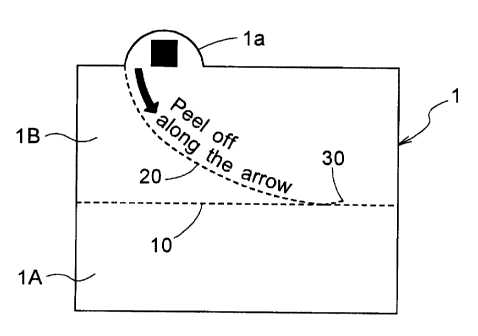
At the upper edge of the upper portion 1B of the sealing label l,
there is formed a knob portion la in the form of a tongue. The perforations
formed in the sealing label 1 include horizontal perforations 10 consisting of
cut segments 11 and uncut segments 12 extending along the border between
the upper portion 1B and the lower portion 1A and inclined perforations 20
consisting of cut segments 21 and uncut segments 22 extending obliquely in
the upper portion 1B from the knob portion la to the horizontal perforations
10. Thus, when tightly fitted to the container 2, the horizontal perforations
10 are to be located along the border between the barrel portion 3 and the
cap portion 4 of the container 2.
Further, in this embodiment, as best shown in Fig. 2, there are
provided additional perforations 30 extending from a contact point between
an elongate uncut segment 13 of the horizontal perforations 10 having a
greater length than the other uncut segments 12 thereof and the cut
8
CA 02381631 2005-05-18
segment 21 of the inclined perforations so as to form a V-shaped region with
the inclined perforations 20, in mirror symmetry and with forming 120
degree angle relative to the inclined perforations. The additional
perforations 30 have a length of one or two cut segments 31 and uncut
segments 32.
The elongate uncut segment 13 of the horizontal perforations 10
forming the contact point area with the inclined pet~'orations 20 has a length
of about 2 mm. Whereas, the other uncut segments 12 of the horizontal
perforations 10 have a length of about 0.5 mm. Further, each cut segment
11 of the horizontal pei~'orations 10 has a length of about 2.5 mm.
The inclined perforations 20 are provided in the form of
downwardly convex curved perforations in the instant embodiment and its
cut segment 21 has a length of about 3.5 mm and its uncut segment 22 has a
length of about 0.5 mm, respectively.
Fig.4 shows an eye dropper container 2 sealed with the sealing label 1
having the above-described construction. Fig. 5 illustrates a condition in
which the seal is cut, i.e. broken, by turning the cap portion 4 of this eye
dropper container 2.
Incidentally, as may be apparent from Figs. 4 and 5, the sealing
label 1 affixed to the eye dropper container 2 will be cut and broken by
turning the cap
portion 4 as described above. However, if the above-described additional
perforations 30 are omitted (see Fig. 3), when the turning of the cap 4
begins,
the uncut segments 12 and the elongate segment 13 of the horizontal
perforations 10 will be cut also. In this, however, as the inclined
perforations 20 were heat shrunk to fit tightly to the cap portion 4, its
uncut segments 22 will remain uncut. In this mode of embodiment, for
removing the upper portion 1B of the sealing label l, it is necessary to cut
one by one the uncut segments 22 of the inclined pet~orations 20 by holding
the knob portion la.
On the other hand, when the additional perorations 30 are
9
CA 02381631 2005-05-18
provided, in association with the start of turning of the cap portion 4, due
to
a cushioning effect provided by the V-shaped cut portion formed by the two
cut segments 21, 31 forming the crossing portion between the inclined
perforations 20 and the additional perforations 30, the uncut segment 22 of
the inclined perforations 20 will begin to be broken before the elongate
uncut segment 13 is broken. So that, only a sealing label portion 1Ba
upwardly of the inclined perforations 20 will be rotated together with the
turning cap 4. And, as the cap portion 4 is moved upward with further
rotation thereof, as illustrated in Fig. 5, the inclined perforations 20 will
be
broken successively upwards and a sealing label portion 1Ba downwardly of
the inclined perforations 20 will become bent. In this manner, as the
triangular portion 1Ba separated in the above manner will be bent in a
complex manner, this will provide clear trace of the seal broken event. At
the same ttimme, as such bent and curled portion cannot be easily restored, it
also becomes impossible to restore the seal on purpose so as not to leave any
trace of the seal broken event.
[Second Embodiment]
Next, a second embodiment of the present invention will be
described with reference to Fig. 6.
Fig. 6 is a development of a sealing label 1 according to the second
embodiment of the present invention. In this sealing label 1, its inclined
pex~'orations 20 consists of two straight series of perorations which are to
form a single continuous series of perforations when the label is wrapped
around the container 2. In this respect, this embodiment differs from the
foregoing embodiment.
[Still Further Embodiments]
10
CA 02381631 2005-05-18
Fig. 7 is a development of a sealing label 1 according to a third
embodiment of the present invention. This sealing label 1 has an upper
portion 1B which is sized so that when the label is tightly fitted to the
container 2 for sealing it, the leading end of the knob portion la will be
located at substantially the top face edge of the cap portion 4.
Further, Fig. 8 is a development of a sealing label 1 according to a
fourth embodiment of the present invention. This sealing label 1 has an
upper portion 1B which is sized so that when the label is tightly fitted to
the
container for sealing it, the leading end of the knob portion la will be
located
spaced apart by a predetermined distance from the top face edge of the cap
portion 4.
In the case of an eye dropper, various data or information may
sometimes be provided on the top face of the cap portion 4. Then, the third
embodiment or fourth embodiment will be employed when it is necessary to
prevent this display from being concealed by the sealing label. Further, by
employing the construction with the knob portion la not projecting from the
top face of the cap portion 4, this will achieve further effect of reducing
the
trouble of hooking of the knob portion 1a during a labeling step or a box
packaging step in the manufacture process. Further, as the sealing label
per se may be foamed smaller, the material cost may be reduced as well.
Figs. 9 and 10 are a perspective view of the eye dropper container 2 sealed
with the sealing label according to the fourth embodiment and a perspective
view illustrating a condition when an attempt has been made to break the
seal by turning the cap portion 4 of this eye dropper container 2,
respectively.
INDUSTRIAL APPLICABILITY
When a user tzzes to break the sealing label 1 by holding the knob
portion 1a, the sealing label 1 may be removed smoothly with a single action.
Further, the sealing may be broken also only by turning the cap portion 4 of
11
r
CA 02381631 2002-02-14
the container 2 sealed with this sealing label 1. In doing this, the
triangular separated portion 1Ba will always leave the curved trace which
can be easily recognized and which cannot be restored, so that the
tamperproof function is provided.
10
20
30
12