Note: Descriptions are shown in the official language in which they were submitted.
CA 02382173 2002-02-15
WO 01/13008 PCT/US00/03190
TORQUE TRANSFER DEVICE
FIELD OF THE INVENTION
This invention relates to a device for transferring torque.
BACKGROUND OF THE INVENTION
There are many devices which transfer torque, or rotational velocity,
from one point to another. Chains, belts and similar direct drive means
transfer
rotational movement from one gear or pulley or similar drive means to a second
or subsequent gear or pulley or similar driven means.
In some applications, it is desirable to transfer relatively high torque from
one point to another point, or from one device to another device. In such
applications, space limitations may be a factor. The relatively high torque to
be it
was the transferred may preclude the use of torque transfer devices which
cannot handle heavy duty loads, while space does not permit the use of large
devices. An example of such space limitations are torque transfer devices
which are placed within enclosures. Examples of devices which transfer
relatively high torque are tools which are used to tighten fasteners by the
application of torque. Engines and motors use torque transfer devices both
operationally, such as camshaft drives, and as power take off devices, such as
chain drives on motorcycles. High torque and limited space is a factor in such
devices.
Various wrenches, extensions, ratchets, adapters and power transfer
tools and devices are disclosed in the prior art. Similarly, camshafts and
similar
devices are driven by the application of relatively high torque where space
for
the application of the drive means is limited. Problems are encountered with
1
CA 02382173 2002-02-15
WO 01/13008 PCTNS00/03190
such devices where the devices are enclosed in relatively small housings, or
are
otherwise required to be relatively compact in comparison to the torque to be
transferred. Common problems experienced with the devices of the prior art
include friction and wear between the housing of the device and the drive
means, inadequate strength of the drive means or gears, and inadequate or
improper engagement of the drive means and the gears due to space
limitations.
An additional problem which is experienced relates to stretching of the
drive means. The drive means is subjected to substantial forces as power is
transferred from one drive gear to the other drive gear. Over time, the drive
means will stretch, causing problems in the operation of the device.
Other drive means jam or bind due to bunching of the drive means at the
points of entry or exit to the drive sprockets. The path travelled by the
drive
means or the structure of the drive means causes such jamming or binding.
SUMMARY OF THE PRESENT INVENTION
The present invention is a device which transfers torque from one point
to a second remote point of the device. A drive means or drive tool inputs
torque into the device at a first point, and the rotational movement, and
torque,
is taken, or harvested, from the second remote point. Typically, the transfer
of
the rotation by the tool will be along a path of travel which is not on the
same
axis as the rotation of the drive tool.
The invention incorporates a direct drive means which connects a first
drive sprocket to a second drive sprocket. The first sprocket rotates as
torque is
applied to the first sprocket, and as the direct drive means is engaged by the
2
CA 02382173 2002-02-15
WO 01/13008 PCT/US00/03190
first sprocket, the direct drive means engages the second drive sprocket,
causing it to rotate.
The direct drive means is comprised of a plurality of pins, which form a
continuous loop. The pins engage the drive sprockets as the pins are
advanced. The pins are not connected to each other. Except when the pins are
engaging the drive sprockets, each pin contacts two other pins, with each pin
being pushed by an adjoining pin, and each pin pushing an adjoining pin.
Forming the direct drive means from a series of pins which contact each other,
but which are not connected, eliminates problems which are associated with
wear when chains or belts are used as the drive means. The pins will not
stretch or break, and are able to handle high torque loads. The pins
inherently
have an arcuate surface which acts as a bearing surtace with regard to the
other
pins and the sprockets.
The pins are formed to have a reduced center dimension, and are
shaped like a dumb bell. The space between the teeth of the drive sprocket is
enlarged at the outside, and the space is of reduced size nearest the hub of
the
sprocket.
The interaction of pins, the housing, the shedder and the drive sprockets
according to the invention prevents jamming of the pins.
DESCRIPTION OF THE DRAWINGS
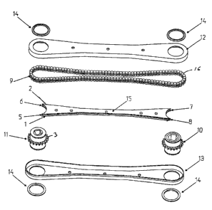
Figure 1 is an exploded view of the device.
Figure 2 is a partially sectioned view of the device.
Figure 3 is a partial view of the device.
Figure 4 is a perspective view of an isolated pin.
3
CA 02382173 2002-02-15
WO 01/13008 PCTNS00/03190
DESCRIPTION OF THE PREFERRED EMBODIMENT
The present invention is characterized by a direct drive means which is
driven by a first drive sprocket, or gear, or similar rotational device. The
direct
drive means, in tum, drives a second drive sprocket, or gear, or pulley, or a
similar rotational device. The direct drive means transfers torque from the
first
rotating member, or sprocket, to a second, or perhaps subsequent, sprocket.
Figure 1 shows the elements of the device. The direct drive means 9 is
comprised of a plurality of pins 16. The pins abut each other as shown, but
are
not attached to each other.
The housing is shown in two parts 12,13 with the housing split for
assembly and subsequent access. One sprocket 11 has a void for a
rectangular drive, and the remaining sprocket 10 has a hexagonal void,
although
other configurations could be used. Snap rings 14 may be provided for the
sprockets to hold the sprockets in place. A shedder 15 is centrally disposed
within the housing to direct the travel of the pins.
The device is contained within the housing. The housing may be
elongated. The housing may have a race formed in it in which the pins track.
The shedder directs the pins through the housing. The shedder and the
interior walls of the housing direct the travel of the pins. The pins are not
connected to each other.
The pins form a continuous loop direct drive means. The continuous
loop direct drive means rotates through a first drive sprocket 10 and a second
drive sprocket 12. The first drive sprocket receives torque from an external
input
source, and is the drive sprocket. The drive sprocket rotates, and each tooth
of
the drive sprocket engages a pin, pushing the pin through the drive sprocket,
and pushing the pin as it exits the tooth of the drive sprocket. The force
applied to a pin as it exits the drive sprocket causes the pin to move along.
As
4
CA 02382173 2002-02-15
WO 01/13008 PCT/US00/03190
the pin exits the tooth which it occupied, the pin pushes the adjoining pin
which
abuts, and is ahead of, the pin. Each pin, in tum, pushes the pin adjoining it
and
ahead of it, advancing the pins, and advancing the continuous loop direct
drive
means.
As the pins enter the second, or driven, sprocket, they engage the teeth
and push the driven sprocket, causing it to rotate. A tool or other device may
be attached to the driven sprocket, and torque taken or harvested from the
driven sprocket. The pins exit the driven sprocket, and engage the shedder,
and continue to be pushed through the housing, and back to the drive sprocket.
Each pin contacts two pins at all times, except while the pin is engaged
within a
tooth of the drive sprockets. The pin behind in the direction of travel pushes
the
pin ahead, in a chain, providing the continuous direct drive means.
The pins contact each other along curved surfaces on the ends 17 of the
pins. The curved surfaces act as bearings, and since they are not connected to
each other or to the housing, the pins can rotate about their axis. This
structure
yields a direct drive means which is low in associated friction, resulting in
minimal wear, as compared with chain drives formed of connected links. A
relatively large number of pins is used, since the pins are relatively small
in
comparison to the size of the overall device.
The pins 16 have a reduced center dimension, and have a greater
dimension on each end. As shown in Figure 4, the pins are shaped like a dumb
bell used in weight lifting, except that they will typically be substantially
smaller
and lighter than an actual dumb bell. The key feature of the embodiment of the
pins as shown is that they are larger on each end than in the center. As
shown,
each end 17 of the pin is of one diameter, and the center 18 is of a smaller
diameter than the ends. This structure allows engagement of the pins with the
shedder and with the teeth 3 of the sprocket. The interaction of pins, the
5
CA 02382173 2002-02-15
WO 01/13008 PCT/US00/03190
housing, the shedder and the drive sprockets according to the invention
prevents jamming of the pins.
The drive sprockets are adapted to engage the pins. The space
between each tooth of the drive sprockets has a relatively large opening which
is
reduced in size as the space approaches the center of the sprocket. The larger
opening assists in initially engaging the center 18 of the pins, and the
smaller
portion of the opening is of only slightly larger dimension than the center of
the
pin, to engage and hold the pin firmly about the center. In the preferred
embodiment, the space 20 has a first larger radius near the outside of the
drive
sprocket, and a smaller radius nearer the center of the drive sprocket. This
use
of two non-concentric intersecting voids of larger and smaller radii to form
the
space between the sprockets results is a shape which has the appearance of a
cross section of a bell, and is referred to herein as the "bell shaped space."
Figure 3. The smaller interior radius of the bell shaped space is slightly
larger
than the radius of center of the dumb bell shaped pin of the preferred
embodiment, so that the center of the pin is accepted and engaged. Play is
minimized between the pin and the sprocket for efFcient torque transfer, but
the
tolerance between the teeth and the pin allows the pin to be readily engaged
and released for smooth operation of the device.
The shedder 15 has an upper leaf 2 and lower leaf 1. Each end of the
shedder is formed in an arcuate shape. A void is present between the upper
leaf and lower leaf on each end which accepts each of the drive sprockets
therein . The teeth of the drive sprockets enter the void between the leaves
as
shown in Figure 2.
The upper leaf and the lower leaf are formed so that the shedder enters
the center 18 of each of the pins. The shedder guides the pins as the pins
travel
between the drive sprockets. The centers of the pins ride along the sides of
the
6
CA 02382173 2002-02-15
WO 01/13008 PCT/US00/03190
shedder, with the sides of the shedder acting as guide rails. Accordingly, the
space between the ends of the pins where the center is located is slightly
greater than the thickness of the shedder, so that the pins can ride on the
shedder and be guided by it. The space between the upper leaf and the lower
leaf is sufficient to allow the teeth of the drive sprockets to pass between
the
upper leaf and the lower leaf. In the preferred embodiment, the shedder is
formed of an upper leaf, a center leaf, and a lower leaf, which fit together
in a
sandwich. The center leaf does not extend to either end, so that the void
between the upper and lower leaves is present.
The interior side walls of the housing and the shedder guide the pins into
the teeth of the sprocket. As the pins enter the drive sprocket, the larger
opening of the bell shaped space between the teeth of the sprocket yields a
relatively sharp tooth which facilitates picking the pins from the shedder.
Once
the pin is picked by the drive sprocket, the pin is forced into the smaler
opening
in the bell shaped space by the interior wall of the housing. The arcuate
shaped
ends of the shedder are of slightly larger radius than the center hub of the
drive
sprocket, so that the shedder extends relatively far toward the drive
sprocket.
This structure is facilitated by the space between the void between the upper
and lower leaf of the shedder, which allows the teeth of the drive sprocket to
enter the end of the shedder.
Accordingly, the guiding of the pins by the housing and the shedder is
along a precise path. The elongation of the shedder, enabled by the void
between the leaves, and the dumb bell shaped pins, which allow the shedder to
engage the pins, provide an efFcient guide for the pins onto and off of the
drive
sprockets. In particular, the pins enter and exit the drive sprockets without
jamming at the entry and exit points. The radius of the housing on each end is
such that the pins are held within the teeth of the drive sprocket by the
housing
7
CA 02382173 2002-02-15
WO 01/13008 PCT/US00/03190
as shown in Figure 3. The distance from the deepest point of the space in the
teeth to the inside of the housing at the radius on each end of the housing is
slightly more than distance d'. Similarly, the distance between the housing
and
the shedder is slightly more than distance d' as the pins travel along the
shedder.
The elongation of the shedder allowed by the voids also allows the
points 5, 6, 7, 8 to be formed in the shedder. The points pick the pins
exiting
the teeth of the drive sprocket. The sides of the spreader, which are extended
over the teeth of the drive sprockets, allow the pins to enter the teeth on
what is
very Gose to a tangent line, so that the pins are picked smoothly from the
shedder by the sprocket. As the pins leave the sprocket, the points of the
shedder pick the pins from the teeth and place them back on the shedder, on an
initial line along the shedder that is almost a tangent line. Entry of the
pins into
the drive sprocket is at a very low angle of attack to the sprocket, and
departure
of the pins from the sprocket occurs with only a small change in the angle of
travel of the pins. This structure provides for very smooth operation of the
device without jamming or binding of the pins, which are not interconnected.
The present invention may be used with hand tools or power tools.
Hand tools and power tools commonly use six point, or hexagonal, engagement
means, or twelve point engagement means. Torque is applied from another
rotating device, or drive means. The rotating device could be any known tool,
including a wrench, ratchet, screwdriver, or a power tool, a motor, or a
transmission, or other device which will apply a rotational force to the
sprocket.
The rotation of the direct drive means by the first sprocket causes rotation
of the
second sprocket. In this manner, torque is transferred to the second sprocket.
Power take off means may be supplied, and application means, such as a tool,
a generator, a pump, or other device which is actuated by the application of
8
CA 02382173 2002-02-15
WO 01/13008 PCT/US00/03190
torque could be used. For the purpose of increasing or decreasing torque, or
increasing or decreasing rotational speed, sprockets of different effective
diameters could be employed, with the housing modified accordingly.
The housing may have various shapes, although the reduced center
dimension as shown is preferred. An object of the present invention is to
provide a device which will transfer torque to a point where there is
difficulty in
positioning a drive. The use of the housing as shown provides relatively
straight
lines of travel for the pins between the sprockets, while also providing a
housing
of minimum dimensions for working in tight spaces.
The best mode for using the device is as extension for tools. A drive,
such as the drive of a ratchet or air wrench is inserted into the first drive
sprocket. The direct drive means transfers torque to the second drive
sprocket,
and a socket or other tool can be used to tighten or loosen a threaded
fastener
at a location which is remote from the wrench. The device is particularly
suited
to such an application since tools for torquing threaded fasteners must be
able
to handle high torque, while the space in which such tools are used is
frequently
limited, meaning that the tool must be as small as possible. Other uses for
the
device are apparent from the disclosure of the device herein.
9