Language selection

Search

Patent 2382240 Summary

Third-party information liability

Some of the information on this Web page has been provided by external sources. The Government of Canada is not responsible for the accuracy, reliability or currency of the information supplied by external sources. Users wishing to rely upon this information should consult directly with the source of the information. Content provided by external sources is not subject to official languages, privacy and accessibility requirements.

Claims and Abstract availability

Any discrepancies in the text and image of the Claims and Abstract are due to differing posting times. Text of the Claims and Abstract are posted:

  • At the time the application is open to public inspection;
  • At the time of issue of the patent (grant).
(12) Patent: (11) CA 2382240
(54) English Title: A VIDEO SURVEILLANCE SYSTEM CONCEALED IN AN ELONGATED TUBULAR HOUSING OBLIQUE TO A WALL
(54) French Title: SYSTEME DE SURVEILLANCE VIDEO DISSIMULE DANS UN LOGEMENT TUBULAIRE ALLONGE OBLIQUE PAR RAPPORT A UN MUR
Status: Deemed expired
Bibliographic Data
(51) International Patent Classification (IPC):
  • H04N 7/18 (2006.01)
(72) Inventors :
  • LEITGEB, DENNIS R. (United States of America)
(73) Owners :
  • LEITGEB, DENNIS R. (United States of America)
(71) Applicants :
  • LEITGEB, DENNIS R. (United States of America)
(74) Agent: BROUILLETTE LEGAL INC.
(74) Associate agent:
(45) Issued: 2010-02-16
(22) Filed Date: 2002-04-17
(41) Open to Public Inspection: 2002-10-25
Examination requested: 2004-07-02
Availability of licence: N/A
(25) Language of filing: English

Patent Cooperation Treaty (PCT): No

(30) Application Priority Data:
Application No. Country/Territory Date
09/843,380 United States of America 2001-04-25

Abstracts

English Abstract

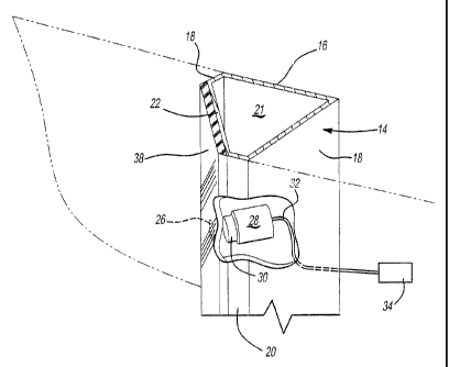
A video surveillance system is disclosed having an elongated tubular housing. The housing includes a planar back wall, a pair of spaced side walls, and a front wall extending between the side walls. The front wall further includes a portion lying in a plane oblique with respect to a plane of the back wall and the back wall, front wall. and side walls together form an interior chamber in the housing. An opening is formed in the oblique portion of the front wall, and a video camera having a lens is mounted within the housing chamber so that the camera lens is aligned with the housing opening. The camera produces an output signal representative of the video picture at the camera lens which is electrically connected to video processing equipment, such as a recorder. The housing itself is mounted to a stationary structure, such as a building.


French Abstract

L'invention concerne un système de surveillance vidéo ayant un logement tubulaire allongé. Le logement comprend un mur arrière planaire, une paire de murs latéraux espacés et un mur avant s'étendant entre les murs latéraux. Le mur avant comprend en outre une partie oblique par rapport à un plan du mur arrière; le mur arrière, le mur avant et les murs latéraux forment ensemble une chambre intérieure dans le logement. Une ouverture est formée dans la partie oblique du mur avant, et une caméra vidéo dotée d'une lentille est fixée dans la chambre du logement de sorte que la lentille de la caméra soit alignée avec l'ouverture du logement. La caméra produit un signal de sortie représentatif de l'image vidéo sur la lentille de caméra qui est électriquement connectée à un dispositif de traitement vidéo, tel qu'un enregistreur. Le logement en soi est fixé sur une structure stationnaire, comme un immeuble.

Claims

Note: Claims are shown in the official language in which they were submitted.


I claim:

1. A video surveillance system comprising:

an elongated tubular housing, said housing having an elongated planar back
wall, a
pair of spaced elongated side walls, and an elongated front wall extending
between said side
walls, said front wall having a portion lying in a plane oblique with respect
to a plane of the
back wall, said back, front and side walls forming an interior chamber in said
housing,
said housing having an opening in said portion of said front wall,
a video camera having a lens, said video camera being mounted in said housing
chamber so that said camera lens is aligned with said housing opening, said
camera
producing an output signal representative of the video picture at said camera
lens, and
a transparent shield secured to said portion of said housing front wall along
the length
of said housing,
wherein said shield is tinted to thereby visually obscure the camera lens from
a
position exterior to said housing,
wherein said housing is adapted to be mounted to a stationary building,
wherein said
housing is dimensioned so that said housing extends along the length of the
building and
simulates a decorative molding strip.

2. The system as defined in claim 1 wherein said shield comprises a plastic
sheet,
said sheet being adhesively attached to said portion of said housing front
wall.

3. The system as defined in claim 1 wherein said housing comprises an
extrusion.

4. The system as defined in claim 1 wherein said housing comprises a metal
extrusion.

5. The system as defined in claim 1 wherein said housing comprises an
aluminum extrusion.

6. The system as defined in claim 1 and comprising means to record said output

signal from said camera.

7. The system as defined in claim 1 and comprising foam disposed in said
housing chamber around said camera.

Description

Note: Descriptions are shown in the official language in which they were submitted.


CA 02382240 2008-04-10

A VIDEO SURVEILLANCE SYSTEM CONCEALED IN AN
ELONGATED TUBULAR HOUSING OBLIQUE TO A WALL
Background of the Invention

1. Field of the Invention

The present invention relates to a video surveillance system.
II. Description of Related

In order to combat crime, many establishments, such as retail
establishments, office buildings, and the like utilize video surveillance
cameras
to monitor the premises. Oftentimes, the output from the video camera is

recorded using video recording equipmerit while, in other cases, security
personnel view monitors from the video cameras in an effort to police the
premises and reduce crime.

Many of these previously known surveillance cameras, however, are
simply placed in open view on the premises. This, however, suffers from two
disadvantages.

One disadvantage of openly mounteci video surveillance cameras is that
criminals, noting the position of the video cameras, are frequently able to
evade
the video camera by carefully moving around the video camera. For example,
for a video camera mounted on the exterior of a building at an elevated height

and facing downwardly, seasoned criminals are able to evade the camera by
merely walking closely along the side of the building.

A still further disadvantage of these openly mounted video cameras is
that the video cameras are subject to attack by criminals in an effort to
disable
the camera. Since video cameras are relatively delicate electronic
instruments,

1


CA 02382240 2002-04-17

merely striking the video camera with a blunt instrument, such as a metal bar,
is sufficient to disable the camera.

Summary of the Present Invention

The present invention provides a surveillance system which overcomes
all of the above-mentioned disadvantages of the previously known devices.

In brief, the surveillance system of the present invention comprises an
elongated tubular housing having a planar back wall, a pair of spaced side
walls and a front wall extending between the side walls. This front wall
includes a portion which extends obliquely with respect to the plane of the
back

wall. Furthermore, the back wall, side walls and front wall of the housing
form
an interior housing chamber.

An opening is formed in the oblique portion of the front wall of the
housing. A video camera having a lens is then mounted within the interior of
the housing so that the camera lens is aligned with the opening in the oblique

housing portion. The video camera provides an output signal representative of
the view as seen by the camera lens. This camera output signal is coupled to
conventional video processing equipment, such as video monitors, a video
recorder or the like.

In the preferred embodiment of the invention, a transparent, but tinted,
shield is disposed along the oblique wall portion. This transparent shield not
only obscures the housing opening, and thus the camera lens, from view but
also renders the overall housing decorative in appearance.

2


CA 02382240 2002-04-17

The housing back wall is then secured to a stationary structure, such as
a building wall, so that the elongated housing has the appearance of a
decorative strip on the structure. Since the housing is secured to the
structure,
the housing remains both stationary and protects the interior camera from

attack. Furthermore, since the entire housing has the overall appearance of a
decorative strip, even seasoned criminals will be unaware that the housing
contains a camera and thus be unable to avoid the video camera.

Brief Description of the Drawing

A better understanding of the present invention will be had upon
reference to the following detailed description, when read in conjunction with
the accompanying drawing, wherein like reference characters refer to like
parts
throughout the several views, and in which:

FIG. 1 is a perspective view illustrating a preferred embodiment of the
present invention secured to a building;

FIG. 2 is a sectional view taken substantially along line 2-2 in FIG. 1
and enlarged for clarity; and

FIG. 3 is a fragmentary front view illustrating a portion of the preferred
embodiment of the present invention.

Detailed Description of a Preferred
Embodiment of the Present Invention

With reference first to FIG. 1, a preferred embodiment of the
surveillance system 10 of the present invention is there shown mounted to a
structure 12, such as a building. The surveillance system 10 includes an
elongated housing 14 which will be subsequently described in greater detail.
3


CA 02382240 2008-04-10

Furthermore, although only one housing 14 is shown mounted to the building
in FIG. 1, it will be understood that the surveillance system may include
multiple housings 14 as desired.

With reference now to FIGS. 2 and 3, the housing 14 is elongated and
tubular in shape having a planar back wall 16, a pair of spaced side walls 18
and a front wall 20 extending between the side walls 18. Furthermore, this
front wall 20 includes a planar portion 22 which lies in a plane oblique with
respect to the plane of the back wall 16. The housing back wall 16, side walls
18 and front wall 20 together form an interior housing chamber 21 which
extends along the length of the housing 14.

Still referring to FIGS. 2 and 3, an opening 26 is formed in the oblique
portion 22 of the housing front wa1120. A video camera 28 having a lens 30 is
then mounted by any conventional means within the housing chamber 21 so
that the lens 30 is aligned with the housing opening 26. The video camera 28

thus provides an output signal on an output line 32 representative of the
image
viewed by the camera lens 30. This ouitput line 32 is then electrically
connected to video processing equipment 34 (FIG. 3), such as a video monitor
or video recording equipment.

As best shown in FIG. 3, the housing; chamber 21 around the camera 28
is preferably filled with a foam 36. This foam protects the video camera 28
from moisture and other condensation and is particularly desirable where the
housing 14 is mounted to an exterior wall of a structure 12 (FIG. 1).

4


CA 02382240 2008-04-10

As best shown in FIGS. 2 and 3, an elongated transparent strip 38, such
as a plastic strip, is secured along the oblique portion 22 of the housing
front
wall 20. This strip 38 is secured to the hoiusing front wall portion 22 by any
conventional means, such as an adhesive, and preferably extends along the

entire length of the housing 14. The strip 38, furthermore, is preferably
tinted
so that the strip 38 obscures the opening 26 in the housing wall portion 22
and
thus obscures the camera lens 30 from sight.

Referring again to FIG. 1, the housing 14 is secured to the structure 12
by any conventional fashion, such as by bolting the housing back wall 16 onto
the structure 12, so that the housing 14 extends along the length of the
structure

12. In doing so, the housing 14 together with the strip 38 provides an
appearance of a decorative molding strip on the housing 12. As such, even
seasoned criminals will be unaware that the housing 14 contains a hidden
surveillance video camera 28.

The present invention thus provides several advantages over the
previously known exposed surveillance cameras. First, since the video camera
28 is contained within the housing chambei- 21 and the housing 14, in turn, is
securely mounted to the structure 12, the housing 14 protects the video camera
28 from attack even if a criminal suspects that the housing 14 contains a
hidden
camera.

Perhaps more importantly, however, is that, since the video camera 28
is mounted to the oblique portion 22 of the housing front wall 20, the video
camera 28 provides a view down along the side of the structure 12. As such, it
5


CA 02382240 2002-04-17

will not be possible for criminals to avoid capture by the surveillance camera
28 by merely walking closely along the side of the structure 12.

From the foregoing, it can be seen that the present invention provides a
simple and yet effective surveillance system that not only hides and protects
the video camera, but also provides an enhanced view along the side of the

building structure 12. It will also be understood, of course, that multiple
housings 14, together with their hidden cameras 28, can be employed to
provide a full vision along all of the sides of the building 12.

Having described my invention, however, many modifications thereto
will become apparent to those skilled in the art to which it pertains without
deviation from the spirit of the invention as defined by the scope of the
appended claims.

I claim:

6

Representative Drawing
A single figure which represents the drawing illustrating the invention.
Administrative Status

For a clearer understanding of the status of the application/patent presented on this page, the site Disclaimer , as well as the definitions for Patent , Administrative Status , Maintenance Fee  and Payment History  should be consulted.

Administrative Status

Title Date
Forecasted Issue Date 2010-02-16
(22) Filed 2002-04-17
(41) Open to Public Inspection 2002-10-25
Examination Requested 2004-07-02
(45) Issued 2010-02-16
Deemed Expired 2018-04-17

Abandonment History

There is no abandonment history.

Payment History

Fee Type Anniversary Year Due Date Amount Paid Paid Date
Application Fee $300.00 2002-04-17
Maintenance Fee - Application - New Act 2 2004-04-19 $100.00 2004-03-30
Request for Examination $800.00 2004-07-02
Maintenance Fee - Application - New Act 3 2005-04-18 $100.00 2005-03-29
Maintenance Fee - Application - New Act 4 2006-04-17 $100.00 2006-04-04
Maintenance Fee - Application - New Act 5 2007-04-17 $200.00 2007-03-09
Maintenance Fee - Application - New Act 6 2008-04-17 $200.00 2008-04-17
Maintenance Fee - Application - New Act 7 2009-04-17 $200.00 2009-04-08
Final Fee $300.00 2009-04-09
Maintenance Fee - Patent - New Act 8 2010-04-19 $200.00 2010-04-16
Maintenance Fee - Patent - New Act 9 2011-04-18 $400.00 2012-04-18
Maintenance Fee - Patent - New Act 10 2012-04-17 $450.00 2012-08-10
Maintenance Fee - Patent - New Act 11 2013-04-17 $250.00 2013-04-09
Maintenance Fee - Patent - New Act 12 2014-04-17 $250.00 2014-04-14
Maintenance Fee - Patent - New Act 13 2015-04-17 $250.00 2015-04-09
Maintenance Fee - Patent - New Act 14 2016-04-18 $250.00 2016-04-18
Owners on Record

Note: Records showing the ownership history in alphabetical order.

Current Owners on Record
LEITGEB, DENNIS R.
Past Owners on Record
None
Past Owners that do not appear in the "Owners on Record" listing will appear in other documentation within the application.
Documents

To view selected files, please enter reCAPTCHA code :


To view images, click a link in the Document Description column. To download the documents, select one or more checkboxes in the first column and then click the "Download Selected in PDF format (Zip Archive)" or the "Download Selected as Single PDF" button.

List of published and non-published patent-specific documents on the CPD .

If you have any difficulty accessing content, you can call the Client Service Centre at 1-866-997-1936 or send them an e-mail at CIPO Client Service Centre.


Document
Description 
Date
(yyyy-mm-dd) 
Number of pages   Size of Image (KB) 
Representative Drawing 2002-07-11 1 8
Abstract 2002-04-17 1 23
Description 2002-04-17 6 210
Claims 2002-04-17 2 46
Drawings 2002-04-17 1 34
Cover Page 2002-10-16 1 38
Description 2008-04-10 6 197
Claims 2008-04-10 1 39
Representative Drawing 2010-01-21 1 10
Cover Page 2010-01-21 2 45
Assignment 2002-04-17 3 91
Fees 2008-04-17 1 34
Fees 2004-03-30 1 32
Prosecution-Amendment 2004-07-02 1 37
Fees 2005-03-29 1 27
Fees 2006-04-04 1 25
Fees 2007-03-09 1 28
Prosecution-Amendment 2007-10-25 3 108
Prosecution-Amendment 2008-04-10 6 212
Correspondence 2008-04-10 3 111
Assignment 2002-04-17 4 130
Fees 2009-04-08 1 34
Prosecution-Amendment 2009-10-02 1 31
Correspondence 2009-04-09 2 89
Correspondence 2009-12-10 1 25
Fees 2010-04-16 1 201
Fees 2012-04-18 2 45
Correspondence 2012-04-18 3 86
Correspondence 2012-05-07 1 14
Correspondence 2012-05-07 1 17
Fees 2012-08-10 1 44
Fees 2013-04-09 1 163
Fees 2014-04-14 1 33
Fees 2015-04-09 1 33
Fees 2016-04-18 1 33