Note: Descriptions are shown in the official language in which they were submitted.
CA 02382446 2002-02-18
Device for optoelectronic determination of the length and/or
width of a body situated on a support
Specification
Technical field
The invention relates to a device for determining the length and/or the
width of a body situated on a support.
io
The body can, for example, be a person's foot, whereby the device is
intended in this case for determining the length and/or the width of the
foot and, thereby, the correct shoe size.
is Prior art
Such a device, for example, for determining the length of children's
feet, is generally known and is based upon a purely mechanical
measurement of the foot. The previously known device has abutting
Zo rails which are pushed from the front against the toes to determine the
length of the foot and/or from the side against the already fixed foot to
determine the width. As a result of the abutting rails making contact
with the foot, the disadvantage arises of the foot becoming displaced as
a reflex reaction, for example, or the toes pulling in, which can lead to
2s an incorrect measurement; the measured foot length would then be
shorter than the actual foot length. In order to obtain an exact
measurement result, it is therefore necessary to take several
measurements, which is quite unsatisfactory for all involved in the
measuring process. Furthermore, there is generally the risk of reading
3o errors by the device operator, which, when using devices for
determining the length of a person's foot can lead to the allocation of
CA 02382446 2002-02-18
an incorrect shoe size in view of the small gradings in the foot/shoe
size measuring systems.
Disclosure of the invention
The invention is based on the problem of showing a device for
determining the length and/or the width of a body situated on a
support, in which the above mentioned disadvantages are avoided and
in which contact is only made with the bearing surface of the body.
to Moreover, good accuracy of measurement should be achieved using a
simple, economic design.
This problem is solved according to the invention by the features of
Claim 1. The subclaims refer to advantageous embodiments.
is
In order to solve the problem, a device is provided for
optoelectronically determining the length and/or the width of a body
situated on a support, comprising a first linear guide for determining
the length and/or a second linear guide for determining the width of the
zo body, whereby the first and/or the second linear guide are moveable
along the lengthwise and/or crosswise direction of the support,
whereby the linear guides have at least one optoelectronic probe
respectively and whereby the probes are connected using a signal line
with an evaluation device for converting and displaying the electrical
Zs signal given by the probes as the length and/or the width of the body.
By using such a device, the support only makes contact with the
bearing surface of the body to be measured. The length and/or width is
determined by optical measurement. By using linear guides, the device
has a comparatively simple design and can be economically produced.
3o Moreover, the device has the advantage of being compact in size. The
size is only negligibly greater than the support itself on which the body
2
CA 02382446 2002-02-18
to be measured is situated. The evaluation device can be spatially
separated from the support and the linear guides. The signals sent by
the probes to the evaluation device are converted by the evaluation
device into any measuring system and are displayed and/or outputted
s via an interface on a peripheral unit, for example, on a monitor. Such a
device is particularly advantageous for determining the length and/or
the width of a person's feet since it no longer requires abutting rails
which make direct and close contact with the feet. Also, the risk of
reading errors by the operator is reduced to a minimum by the
io evaluation device and the display on which the size of the body, for
example, in millimetres, or the shoe size can be directly read.
Contamination of the support, for example, with dust from the home,
has no negative effect on the measurement result. The claimed device
is therefore has both an excellent degree of reliability and high accuracy
of measurement.
Should the device be provided for determining the length and the width
of a body situated on a support, the linear guides for determining the
Zo length and the width are arranged orthogonal to one another. To obtain
an exact measurement result, it is preferably provided that the support
is connected with the linear guides and that the support and the linear
guides are positioned immovably in relation to one another. Since the
device as a whole is compact in size and, therefore, is easy to
Zs transport, such an embodiment is particularly advantageous with
respect to good accuracy of measurement. The support and the linear
guides form a unit, whereby the unit has simply to be joined to the
evaluation device. Handling is therefore made considerably easier.
Adjusting the linear guides in relation to the support after
30 manufacturing of the device is no longer necessary.
3
CA 02382446 2002-02-18
The probes can be formed as light barriers and have respectively at
least one emitter and at least one detector allocated in a technical,
functional manner to the emitter. Light barriers function reliably and
maintenance-free over along usable life, which is especially
s advantageous in view of a technically inexperienced operator.
Preferably, the linear guides are respectively U-shaped and underlap
the support with a connecting frame, whereby the sides of the linear
guides are arranged on opposite sides of the body and whereby one of
io the sides has an emitter and one of the sides of each linear guide has a
detector. The emitters and the detectors of each linear guide are
synchronously moved using the connecting frame.
The measuring beams of the emitter of each linear guide are preferably
is modulated and filtered at the detector and undergo a threshold
weighting in order to avoid malfunctions, for example, as a result of
outside light. The recording, feature extraction and storing of the
detector signals digitalised in this way can occur in a program-
controlled manner during routine probe movement. The evaluation of
Zo the signals takes place, for example, after the completion of the
measuring process without a time limit.
The linear guides can be respectively driven by a stepping motor. The
fundamental principal of the evaluation is based on the fixed
as relationship between the propulsion stepping number and the
respective probe position, such that by counting the motor steps
between two edge changes of the detector signals, a clear allocation of
length is given. The transition of a signal level (voltage level) from one
level value to another level value is referred to as a signal edge,
3o whereby the transition from a lower level value to a higher level value
is referred to as a rising edge and the transition from a higher level
4
CA 02382446 2002-02-18
value to a lower level value is referred to as a falling edge.
The linear guides are moved, for example, in equidistant steps or at a
constant speed. The evaluation device can be formed by an electronic
s module and can comprise, for example, a classification apparatus for
converting the one measuring signal at least into a size classification.
Such an evaluation device is particularly useful when the device is used
for determining the size of a person's foot.
~o Brief description of the drawings
One embodiment of the device according to the invention is described
below in more detail by means of the diagrammatically illustrated
figures.
is
Figure 1 shows a perspective view of the device.
Figure 2 shows a side view of the device. and
Zo Figure 3 shows a top view of the device.
Carrying out the invention
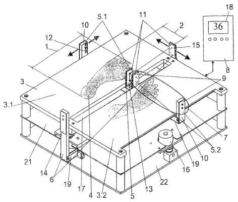
Figure 1 shows one embodiment of the device according to the
as invention. In this embodiment, bodies to be measured 4 are a person's
feet, the length 1 and width 2 of which are determined by
optoelectronic means. Support 3 consists on the side that faces body 4
of a step-on plate 20 comprising two partial surfaces 3.1, 3.2. Partial
surfaces 3.1, 3.2 are separated from one another by gap 17, whereby
3o detectors 11 of both first linear guides 5.1 and 5.2, which are
respectively provided for establishing the length of both feet, are
CA 02382446 2002-02-18
arranged inside gap 17. Both linear guides 5.1, 5.2 are mechanically
coupled with one another and are moveable only together and
synchronously in the lengthwise direction of bodies to be measured 4.
Second linear guide 6 for establishing width 2 of bodies 4 is moveable
s in the crosswise direction of body to be measured 4 and can travel
along the whole width of support 3.
Both first linear guides 5.1, 5.2 are substantially U-shaped, whereby
respective connecting frame 19 runs under step-on plate 20.
io
An intermediate plate 21 is arranged adjacently at a distance under
step-on plate 20, the driving mechanism for both linear guides 5.1, 5.2
being mounted thereon. Driving is performed by stepping motor 16
which is screwed onto intermediate plate 21. Connecting frame 19 of
is second linear guide 6 is arranged between intermediate plate 21 and
base plate 22. Both first linear guides 5.1, 5.2 for establishing the
length of bodies 4 are moveable orthogonal to second linear guide 6.
Both first linear guides 5.1, 5.2 are driven in this embodiment by
common stepping motor 16. Another stepping motor, which is not
Zo illustrated herein, is provided for driving second linear guide 6.
The stepping motors are actuated by evaluation device 8 having,
moreover, display 18 which displays a shoe size in this embodiment.
Display 18 is formed in this embodiment as a liquid crystal matrix
Zs display which can be read without difficulty even under bad lighting
conditions.
First linear guide 5.1, 5.2 and second linear guide 6 are arranged
orthogonal to one another. Optoelectronic probe 7, which is formed by
light barriers 9, is connected using a signal line with evaluation device
30 8, whereby light barriers 9 have an emitter 10 and a detector 11
respectively. Due to sides 12, 13, 14, 15 of linear guides 5, 5.1, 5.2, 6
6
CA 02382446 2002-02-18
being arranged on opposite sides of body 4, these sides travel right
around the feet to be measured which are placed on step-on plate 20,
to calculate the movements of probes 7.
s Figure 2 shows a side view of the device and Figure 3 shows a top view
of the device.
io
is
25
7