Note: Descriptions are shown in the official language in which they were submitted.
CA 02382583 2002-04-18
426BA
SHEET METAL HE~~VIING METHOD AND APPARATUS
Technical Field
This invention relates generally to the hemming of sheet metal and more
particularly, to a hemming apparatus and method for forming a generally flat
hem.
Background of the Invention
It is well known to construct motor vehicle body panels, doors, hoods,
fenders, tailgates, trunks and deck lids by stamping an outer sheet metal
panel and
separately stamping an inner sheet metal reinforcing panel and then joining
the two
panels together by hemming a flange of the periphery of the outer panel over
an adjacent
edge of the inner panel to secure the panels together. Desirably, the outer
panel is slightly
larger than the inner panel to provide a border flange portion along the
periphery of the
outer panel that can be folded over the peripheral edge of the inner panel to
define the
hem flange that connects the two panels.
When the flange is folded over the peripheral edge of the inner panel with
a traditional hemming apparatus and method, the resulting edge of the hemmed
panels
has a generally smooth, curved or arcuate shape with a diameter of the bend
equal to
twice the thickness of the outer panel plus the thickness of the inner panel.
With inner
and outer panels of the same thickness, the diameter of the bend for a
standard hemming
apparatus and method is equal to three times the thickness of a sheet metal
panel. While
many standard hemming methods and devices produce a smooth and fair hem or
fold
line, the relatively large bend diameter of the fold line reflects light in
various directions
along the curved fold line. This creates the visual impression that the gap
between
adjacent hemmed panels of the vehicle body is larger than it actually is, that
the gap is
inconsistent or that the panels are not flush with one another.
1
CA 02382583 2002-04-18
According to known hemming processes, an outer sheet metal panel is
stamped and formed to include a border flange along a periphery of the outer
panel. An
inner sheet metal reinforcing panel is formed and shaped to be slightly
smaller than the
outer sheet metal panel. The inner panel is placed against the outer panel
such that a
S periphery of the inner panel is disposed adjacent and generally parallel to
the border
flange of the outer panel. The two panels are then secured together by hemming
the
border flange of the outer panel over the adjacent periphery of the inner
panel. In more
conventional hemming processes this is done by folding the border flange over
the inner
panel such that the flange lies flat against the inner panel - resulting in a
relatively large
flange bend diameter. In a less-conventional process known as an "open hem"
process,
the panels are secured together by folding the border flange over the inner
panel such that
the flange is inclined against the outer edge of the inner panel and an outer
edge of the
flange is spaced from the inner panel. This leaves a smaller flange bend
diameter but also
leaves an elongated gap between and along the outer edge of the flange and the
inner
panel that foreign material can collect in.
Summary of the Invention
The invention is a sheet metal hemming apparatus for securing two sheet
metal panels together by forming a generally flat hem along respective
peripheries of the
two panels. The apparatus includes a fixture configured to receive and hold a
sheet metal
panel having an upstanding border flange and a hemming tool movably supported
adjacent the fixture and configured to bend the upstanding border flange of a
sheet metal
panel supported on the fixture into a position forming an acute angle relative
to an
underlying portion of the panel. The hemming tool is configured to bend an
outer portion
of the flange into a position over and generally parallel to the underlying
portion of the
sheet metal panel.
The invention also includes a method for forming a generally flat hem
along respective peripheries of the two panels. According to this method one
can secure
two sheet metal panels together by forming a generally flat hem along
respective
peripheries of the two panels. An outer sheet metal panel is formed to include
a generally
upstanding border flange along a periphery of the outer panel. The border
flange is then
folded until the flange is inclined over an underlying portion of the outer
panel. The
2
CA 02382583 2002-04-18
border flange is then further folded such that an outer portion of the flange
is disposed
generally parallel to an underlying portion of the outer panel.
Objects, features and advantages of this invention include providing a
relatively simple hemming apparatus that produces a hemmed flange having a
first
portion inclined relative to a second portion, that provides a hemmed flange
with a
reduced bend diameter, that provides a fold line having a more consistent
appearance
when viewed from different angles, that provides adjacent hemmed panels on a
vehicle
visually appearing to have a narrower or smaller gap between them, that
eliminates the
need for a separate assembly operation to provide sealing material between the
hemmed
flange and inner panel by providing a closed hem, that is readily adaptable
for use with
panels having different configurations, that is reliable, durable, of
relatively simple
design and economical manufacture and assembly and that has a long, useful
service life.
Brief Description of the Drawings
1 S These and other objects, features and advantages of this invention will be
apparent from the following detailed description of the preferred embodiments
and best
mode, appended claims and accompanying drawings in which:
FIG. 1 is a perspective view of an automobile having various body panels
formed from hemmed inner and outer sheet metal panels;
FIG. 2 is a perspective view of the interior of a vehicle door having
hemmed inner and outer sheet metal panels;
FIG. 3 is a cross-sectional view taken generally along line 3 - 3 of FIG.
1;
FIG. 4 is an enlarged fragmentary sectional view of the encircled portion
4 in FIG. 3;
FIG. 5 is a fragmentary sectional view illustrating a prehem tool for
initially bending the flange of the outer sheet metal panel;
FIG. 6 is a fragmentary sectional view illustrating a final hem tool
constructed according to a first embodiment of the invention;
FIG. 7 is an enlarged fragmentary sectional view illustrating an alternative
modified hemmed flange configuration;
FIG. 8 is a fragmentary sectional view similar to that of FIG. 3 but
3
CA 02382583 2002-04-18
illustrating a known hemmed flange configuration;
FIG. 9 is a cross-sectional view of a second hem tool embodiment of the
invention;
FIG. 10 is an end view of a roller of the hem tool of Figure 9; and
FIG. 11 is a cross-sectional view of a third hem tool embodiment of the
invention.
Detailed Description
Referring in more detail to the drawings, FIGS. 1 and 2 illustrate a vehicle
10
having various body panels 12, doors 14, a tnuik 16 and a hood 18 wherein each
may be
formed from inner and outer sheet metal panels 20, 22 connected together by a
hem 24
embodying the invention. As best shown in FIGS. 3 and 4, the various body
panels 12,
14, 16, 18 of the vehicle 10 may each comprise an outer sheet metal panel 22
that is
slightly larger than an inner sheet metal panel 20 and has a border flange 25
along the
periphery of the outer panel 22 that is folded or hemmed over the peripheral
edge 40 of
the inner panel 20 to form the hem 24 connecting inner and outer panels 20, 22
together.
A smooth and fair hem outer edge 26 is required to avoid blemishes on the
finished,
painted panel and to ensure a consistent gap between adjacent panels 20, 22.
Figures S and 6 illustrate a method and a first apparatus embodiment of the
invention for forming a flat hem 24 in the outer sheet metal panel 22 onto the
inner sheet
metal panel 20 to connect the panels 20, 22 together. A second hemming method
and
second and third flange hemming apparatus embodiments for producing flat
modified
hems are shown in Figures 9-11. Reference numerals with the subscript "a" in
Figures 9
and 10 indicate alternative configurations of elements that also appear in the
first
embodiment. Likewise, reference numerals with the subscript "b" in Figure 11
indicate
alternative configurations of elements that also appear in the first or second
embodiments.
Unless indicated otherwise, where a portion of the following description of
the first
embodiment uses a reference numeral to refer to the figures, that portion of
the description
applies equally to elements designated by the subscripts "a" and "b" in
Figures 9-11.
Likewise, unless indicated otherwise, where a portion of the description of
the second
apparatus embodiment uses a reference numeral to refer to the figures, that
portion of the
description applies equally to elements designated by the subscript "b" in
Figure 11.
4
CA 02382583 2002-04-18
The hemming method and apparatus provide a smooth and fair fold line defining
the outer edge 26 of the outer panel 22 having a reduced outside bend diameter
27 that
is less than three times the thickness of a sheet metal panel 20 or 22,
desirably less than
about twice the thickness of a sheet metal panel 20 or 22, and preferably
generally equal
to or less than the thickness of a single sheet metal panel 20 or 22, to
improve the
appearance of the outer edge 26 and of the automotive vehicle body in general.
To
achieve the reduced outside bend radius or diameter 27, the hemming apparatus
and
method produce a hemmed flange 24 that has an inner portion 28 adjacent the
outer edge
26 that is generally flat and inclined relative to an outer portion 30 folded
flat against the
inner sheet metal panel 20.
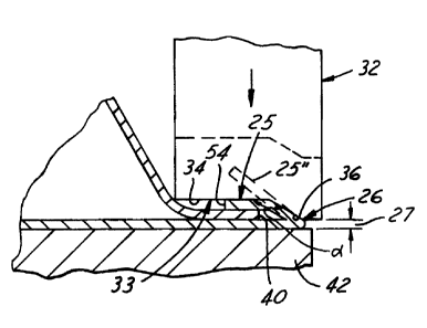
The improved hem 24 may be produced with a standard hemming press using an
improved hemming tool 32 (FIG. 6) with an end forming face 33 having a first,
generally
planar section 34 constructed to form the outer portion 30 of the flange and a
second
portion 36 inclined relative to the first section 34 to form the inner portion
28 of the
flange 24. As best shown in FIGS. 5 and 6, to form the hem, the inner sheet
metal panel
is disposed on the outer sheet metal panel 22 that in turn is received on a
locating and
support fixture 42 in a press. A prehem tool 44 having an inclined forming
face 46 is
preferably carried by an upper platen of a press (not shown) and is advanced
toward and
engages the upstanding flange 25' of the outer sheet metal panel 22 to bend it
from an
20 initial included angle of approximately 90 degrees to a prehemmed acute
included angle
of between 25 and 75 degrees, and preferably about 45 degrees, to form a
prehemmed
flange 25". Thereafter, as shown in FIG. 6, the final hem tool 32 also carned
by an upper
platen of the press, is advanced toward the prehemmed flange 25" to bend the
flange into
its final, hemmed position and form the flange 25 having an outside bend
diameter 27
that is less than three times the thickness of a sheet metal panel 20 or 22.
The final hem tool 32 has a forming face 33 with a generally planer first
section
34 constructed to form the outer portion 30 of the flange 25 substantially
flat onto the
inner sheet metal panel 20 and thus provide a so called "closed hem" without
any gap
between an outside edge 54 of the flange 25 and the inner panel 20. The second
section
36 of the forming face 33 is inclined at an obtuse included angle relative to
the first
section 34 and is also preferably generally planer to form the generally flat,
inclined inner
portion 28 of the hemmed flange 25 immediately adjacent to the outer edge 26
or bend
5
CA 02382583 2002-04-18
in the outer sheet metal panel 22. Desirably, the second section 36 is
disposed at an
included angle of about 100 to 160 degrees relative to the first section 34
and preferably
about 135 degrees. The angle may be varied to permit the location of the
peripheral edge
40 of the inner sheet metal panel 20 to be varied relative to the outer edge
26 or hem line.
Preferably, the second section 36 of the final hem tool 32 does not
immediately overlie
and is spaced outboard of the inner sheet metal panel 20 to prevent the inner
sheet metal
panel 20 from being unduly pinched by the inclined second section 36 of the
hemming
tool 32 and inner portion 28 of the flange 25. Thus, as shown in FIG. 4, the
longitudinal
distance "a" from the peripheral edge 40 of the inner panel 20 to the outer
edge 26 of the
outer panel 22 is preferably greater than the longitudinal distance "b" from
the fold or
bend 56 between the inner portion 28 of the flange 25 and the outer portion 30
and the
outer edge 26 of the outer panel 22.
A modified hem flange embodiment is illustrated at 70 in FIG. 7. The modified
hemmed flange 70 has an outer bend diameter 2T equal to about twice the
thickness of
1 S the outer sheet metal panel 22'. An inner portion 71 of the flange 70 is
folded flat onto
the outer sheet metal panel 22' and an outer portion 72 of the flange 70 is
folded flat or
closed on the inner sheet metal panel 20'. To prevent creasing of the flange
70 and to
provide the outer portion 72 above the inner sheet metal panel 20', a smooth
or generally
arcuate transition or ramp section 74 is preferably provided between the inner
and outer
portions 71, 72 of the hemmed flange 70.
In either hemmed flange embodiment 25,70, the outer bend diameter 27,27 at the
outer edge of the flange 25, 70 is substantially less than in the prior art,
as shown in FIG.
8, wherein the outer bend diameter 80 of an outer panel 82 is equal to the sum
of the
thickness of the inner panel 82 and twice the thickness of the outer panel 84.
If the panels
82 and 84 are of equal thickness the radius of the bend 80 is equal to three
times the
thickness of either panel. Desirably, the outer bend diameter 27 may be
generally equal
to one or two times the thickness of the outer sheet metal panel 22 or less.
The reduced
bend diameter 27,27' of the present invention provides an improved appearance
of the
finished hemmed panels by themselves, and in assembly relative to the prior
art hemmed
panels they appear to have a substantially more uniform and smaller gap and a
flush
alignment.
As with the first method and apparatus embodiment of Figures 1-6, the second
CA 02382583 2002-04-18
embodiment shown in Figures 9 and 10 and the third embodiment shown in Figure
11 are
for forming a flat hem 24a, 24b in an outer sheet metal panel 22a, 22b onto an
inner sheet
metal panel 20a, 20b to connect the panels 20a, 20b; 22a, 22b together.
According to the second embodiment shown in Figures 9 and 10, the apparatus
includes a support fixture in the form of a die ring 42a. The die ring 42a is
shaped to
receive and hold a sheet metal panel, such as the outer sheet metal panel
shown at 22a,
having an upstanding border flange 25a formed along at least a portion of the
panel 22a.
The border flange 25a of the outer sheet metal panel 22a is bendable to the
flanged
position shown in Figure 9. The inner sheet metal panel 20a is stacked on top
of the
outer sheet metal panel 22a in a layered disposition.
A roll hemming tool 60 is movably supported adjacent the fixture 42a and
includes a forming roller 68 that engages and bends the border flange 25a
while rolling
along a length of the border flange 25a. The forming roller 68 is supported by
a bearing
70 that is, in turn, supported on a forming roller axle 72. The forming roller
68 includes
1 S an outer circumferential forming face 62 that actually engages the border
flange 25a. The
forming face 62 includes a fiusto-conical first portion 64 shaped to bend the
upstanding
border flange 25a of the outer sheet metal panel 22a along a first fold line
26a of the
border flange 25a into a position forming an acute angle relative to an
underlying portion
of the inner sheet metal panel 20a as shown in Figure 9. The forming face 62
of the
hemming tool 60 forming roller 68 also has a cylindrical second portion 66
shaped and
positioned to bend an outer portion 30a of the border flange 25a into a
position over and
generally parallel to the underlying portion of the inner sheet metal panel
20a. The second
portion 66 of the forming face 62 bends the outer portion 30a of the border
flange 25a
along a second fold line 56a that is generally parallel to and spaced from the
main fold
line 26a.
The apparatus may also include a pre-hem tool such as the pre-hem tool 44
shown
in Figure 5, that pre-bends the border flange 25a to an acute included angle
relative to the
underlying portion of the panel before the forming roller 68 is used to form
the final hem.
When such a pre-hem tool 44 is used, it bends the border flange 25a to a pre-
hem angle
of between 25 and 75 degrees relative to the underlying portion of the panel.
Whether or not a pre-hem tool is to be employed, the forming roller 68 is
shaped
such that the frusto-conical first portion 64 of the forming surface 62 is
shaped to incline
CA 02382583 2002-04-18
relative to the cylindrical second portion 66 of the forming surface 62 at an
obtuse
included angle of between 110 and 160 degrees depending on, among other
considerations, the thickness of the outer sheet metal panel.
In fabricating the roller 68, the angle of the frusto-conical first portion 64
of the
forming surface 62 is selected to provide a border flange angle that meets
requirements
specified for an intended application. Depending on the selected angle of the
fiusto-
conical first portion 64 of the forming surface 62, a border flange 25a that
is hemmed by
the hemming tool 60 may end up having an outer bend diameter 26a that's less
than three
times the thickness of the outer sheet metal panel 22a, less than twice the
thickness of the
outer sheet metal panel 22a, or that's approximately equal to the thickness of
the outer
sheet metal panel 22a.
The forming roller 68 is supported in a position to hem the border flange 25a
over
a peripheral edge 40a of the inner sheet metal panel 20a as shown in Figure 9.
When the
forming roller 68 engages the border flange 25a, the frusto-conical first
portion 64 of the
forming surface 62 of the forming roller 68 is disposed outboard of the
peripheral edge
40a of the inner panel 20a such that the cylindrical second portion 66 of the
forming
surface 62 of the forming roller 68 overlies the peripheral edge 40a of the
inner sheet
metal panel 20a.
To support the forming roller 68 for rotational and translational motion
relative
to the inner and outer sheet metal panels 20a, 22a, the apparatus includes a
forming roller
support arm 76. The forming roller support arm 76 may extend from any suitable
manipulating means known in the art to include a robot arm or a roll form
hemming
machine. The support arm 76 and manipulating means support the roller axle 72
in such
a way as to allow the roller 68 to be moved along a path that will cause the
roller 68 to
engage and hem the outer panel border flange 25a as described above and shown
in
Figures 9 and 10.
An inner end of the forming roller 68 includes a radially-extending annular
rim
78 configured to guide the forming roller 68 along a periphery 79 of the
fixture 42a. The
radially-extending annular rim 78 is axially biased against the fixture 42a by
a spring 86
disposed axially around the forming roller axle 72. The spring 86 is disposed
between
the forming roller 68 and a spring retainer portion 88 of the forming roller
support arm
76. The spring 86 may be a coil spring, a gas spring or any other suitable
biasing device
8
p..y .. I
CA 02382583 2002-04-18
known in the art.
According to the third flange hemming apparatus embodiment shown in Figure
11, a ball roller 90 is supported on a collar 92 that is fixed to a forming
roller axle 72b
immediately adjacent a forming roller 68b. The ball roller 90 serves the same
purpose
as the radially extending annular rim 78 of the roller 68 in the second flange
hemming
apparatus embodiment of Figures 9 and 10 in that the ball roller 90 is
disposed in a
position to guide the forming roller 68b along a periphery 79b of a die ring
fixture 42b.
However, the ball roller 90 of the third embodiment accomplishes this by
rolling along
an outer side wall 94 of the die ring fixture 42b rather than turning against
the side wall
94.
In practice, the second and third apparatus embodiments may be used to hem two
sheet metal panels together by first providing an outer sheet metal panel 22a,
22b having
a generally upstanding border flange 24a, 24b along a periphery 26a, 26b of
the outer
panel 22a, 22b. An inner sheet metal reinforcing panel 20a, 20b, that is
slightly smaller
than the outer panel 22a, 22b, is then positioned against the outer sheet
metal panel 22a,
22b. The inner panel 20a, 20b is positioned against an inner surface of the
outer panel
22a, 22b such that a peripheral edge 40a, 40b of the inner panel 20a, 20b is
disposed
adj acent and generally parallel to the border flange 24a, 24b of the outer
panel 22a, 22b.
The forming roller 68, 68b is fabricated so that the frusto-conical first
portion 64,
64b of its forming surface 62, 62b is angled to accommodate the thickness of
the inner
panel 20a, 20b and to provide a desired outer panel border flange fold radius.
The
forming roller 68, 68b is then mounted on a support arm 76, 76b of a robot or
a roll
hemming machine that is then programmed or otherwise configured to roll the
forming
roller 68, 68b along the hem. As the forming roller 68, 68b rolls along the
border hem,
the frusto-conical first portion 64, 64b of the forming surface 62, 62b of the
roller 68, 68b
folds the border flange 24a, 24b into its inclined position over the
underlying portion of
the outer panel 22a, 22b while the cylindrical second portion 66, 66b of the
forming
surface 62, 62b simultaneously folds the outer portion 30a, 30b of the border
flange 24a,
24b into a position flat against the inner surface of the inner panel 22a,
22b. This is done
by rolling the forming roller 68, 68b along the border flange 24a, 24b such
that the frusto-
conical first portion 64, 64b of the forming surface 62, 62b rolls along an
inner portion
9
CA 02382583 2002-04-18
98, 98b of the border flange 24a, 24b and the cylindrical second portion 66,
66b of the
forming surface 62, 62b rolls along the outer portion 30a, 30b of the border
flange 24a,
24b. In its inclined position the border flange 24a, 24b forms an acute angle
relative to
the underlying portion of the panel.
Alternatively, a pre-hem roller or steel 44 may be used to fold the border
flange
24a, 24b until the border flange is inclined against the peripheral edge 40a,
40b of the
inner panel 20a, 20b such that a distal edge of the panel is spaced from the
inner surface
of the inner panel 20a, 20b as shown in phantom in Figure 5. One of the two
forming
roller embodiments is then employed to further fold the border flange 24a, 24b
such that
the portion of the border flange 24a, 24b disposed generally parallel to the
underlying
portion of the outer panel 22a, 22b lies flat against the inner surface of the
inner panel
20a, 20b, securing the inner panel to the outer panel.
This description is intended to illustrate certain embodiments of the
invention
rather than to limit the invention. Therefore, it uses descriptive rather than
limiting
words. Obviously, it's possible to modify this invention from what the
description
teaches. Within the scope of the claims, one may practice the invention other
than as
described.
1o