Note: Descriptions are shown in the official language in which they were submitted.
CA 02382679 2002-04-19
In-Situ Transducer Modeling in a Digital Hearing Instrument
CROSS-REFERENCE TO RELATED APPLICATION
This application claims priority from and is related to the following prior
application: In-
Situ Transducer Modeling In a Digital Hearing Instrument, United Stages
Provisional Application
No. 60/284,984, filed April 19, 2001. In addition, this application is related
to the following co-
pending application which is owned by the assignee of the present ;invention:
Digital Hearing
Aid System, United States Patent Application [application number not yet
available], filed April
12, 2001. These prior applications, including the entire written descriptions
and drawing figures,
to acre hereby incorporated into the present application by reference.
BACKGROUND
1. Field of the Invention
This invention generally relates to digital hearing instruments. More
specifically, the
invention provides a method in a digital hearing instrument for in-situ
modeling of the
instrument transducers (i.e., microphone(s) and speaker(s)) using the digital
hearing instrument
a.s a signal processor.
2. Description of the Related Art
2o Digital hearing instruments are known in this field. These instmments
typically include a
plurality of transducers, including at least one microphone and at least one
speaker. Some
instruments include a plurality of microphones, such as a front microphone and
a rear
microphone to provide directional hearing.
1
CA 02382679 2002-04-19
Hearing aid fitting software is often used during the customization of such
instruments in
order to configure the instrument settings for a particular user. This
software typically presents
information regarding the instrument to the fitting operator in the form of
graphs displayed on a
personal computer. The graphs are intended to display the performance o.f the
instrument given
t:he current settings of the device. In order to display these performance
graphs, the fitting
software requires mathematical models of the electrical transfer function of
the instrument in
conjunction with electro-acoustical models of the microphone and the speaker.
Traditionally, the electro-acoustical models of the microphone and the speaker
are
derived independently from the fitting process by skilled technicians. FIG. 2
is a block diagram
1o showing the traditional method of characterizing a microphone in a digital
hearing instrument.
here, the microphone-under-test (MUT) is coupled to a meter 108 for measuring
the voltage
output from the microphone. This measured voltage is applied to a custom test
and measurement
system 104, which is also coupled to a tone generator 106 and an external
speaker 110.
Operationally, the test and measurement system 104 controls the tone generator
106 and causes it
to sweep across a particular frequency range of interest, during which time it
takes measurement
data from the meter 108. The test an measurement system then derives an
electro-acoustical
model 112 of the MLTT' 102 using the data gathered from the meter 108.
FIG. 3 is a block diagram showing the traditional method of characterizing a
speaker in a
digital hearing instrument. Here, the speaker-under-test (SUT) is coupled to
the tone generator
l~ 06. The test and measurement system I 04 causes the tone generator 106 to
drive the SUT with
a known signal level while the acoustic sound pressure developed from the SUT
is quantified by
a test microphone 102 and level meter 108. U sing the data gathered from the
level meter 108,
the test and measurement system 104 then derives the electro-acoustical model
for the SUT 110.
2
CA 02382679 2002-04-19
The problem with the foregoing traditional characterization and modeling
methods is that
the specialized equipment required to derive the models, i.e., the test and
measurement system
1.04 and other equipment, is very expensive, and also requires a skilled
technical operator.
BRIEF DESCRIPTION OF THE DRAWINGS
FIG. 1 is a block diagram of an exemplary digital hearing instrument including
a plurality
of transducers;
FIG. 2 is a block diagram showing the traditional method of characterizing a
microphone
in a digital hearing instrument;
FIG. 3 is a block diagram showing the traditional method of characterizing a
speaker in a
digital hearing instrument;
FIG. 4 is a block diagram showing a method of in-situ transducer modeling
according to
the present invention; and
FIG. 5 is a block diagram showing another method of in-situ transducer
modeling
according to the present invention.
SUMMARY
A method for in-situ transducer modeling in a digital hearing instnunent is
provided. In
one embodiment, a personal computer is coupled to a processing device in the
digital hearing
instrument and configures the processing device to operate as a level detector
and an internal
tone generator. An audio signal generated by the personal computer is received
by a
microphone-under-test (MUT) in the digital hearing instrument and the energy
level of the
received audio signal is determined by the level detector. In addition, an
audio output signal
generated by the tone generator and a speaker-under-test (SUT) in the digital
hearing instrument
3
CA 02382679 2002-04-19
is received by a microphone, and the energy level of the audio output signal
is determined by a
level meter. The energy levels of the received audio signal and the audio
output signal are used
by the personal computer to generate an electro-acoustic model of the digital
hearing instrument.
In another embodiment, the personal computer configures the processing device
in the
digital hearing instrument to operate as a level detector. An audio signal
generated by the
personal computer is received by a MUT in the digital hearing instrument, and
the energy level
of the received audio signal is determined by the level detector. A ,gain is
then applied to the
received audio signal, and the energy level of the amplified audio signal is
determined by the
level detector. The personal computer compares the energy levels of the
received and amplified
l0 audio signals and adjusts the gain such that the digital hearing instrument
meets pre-determined
hearing aid characteristics.
DETAILED DESCRIPTION OF THE DRAWINGS
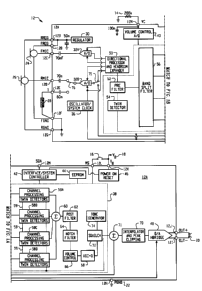
Turning now to the drawing figures, FIG. 1 is a block diagram of an exemplary
digital
hearing aid system 12. The digital hearing aid system 12 includes several
external components
1.4, 16, 18, 20, 22, 24, 26, 28, and, preferably, a single integrated circuit
(IC) 12A. The external
components include a pair of microphones 24, 26, a tele-coil 28, a volume
control potentiometer
24, a memory-select toggle switch 16, battery terminals 18, 22, and a speaker
20.
Sound is received by the pair of microphones 24, 26, and converted into
electrical signals
that are coupled to the FMIC 12C and RMIC 12D inputs to the IC 1 2A. FMIC
refers to "front
microphone," and RMIC refers to "rear microphone." The microphones 24, 26 are
biased
between a regulated voltage output Lrom the RREG and FREE pins 12B, and the
ground nodes
4
CA 02382679 2002-04-19
FGND 12F and RGNI) 12G. The regulated voltage output on FREE and RREG is
generated
internally to the IC 12A by regulator 30.
The tele-coil 28 is a device used in a hearing aid that magnetically couples
to a telephone
handset and produces an input current that is proportional to the telephone
signal. This input
current from the tele-coil 28 is coupled into the rear microphone A/I)
converter 32B on the IC
1.2A when the switch '76 is connected to the "'T" input pin 12E, indicating
that the user of the
hearing aid is talking on a telephone. The tele-coil 28 is used to prevent
acoustic feedback into
the system when talking on the telephone.
The volume control potentiometer 14 is coupled to the volume control input 12N
of the
to IC. This variable resistor is used to set the volume sensitivity of the
digital hearing aid.
The memory-select toggle switch 16 is coupled between the positive voltage
supply VB
1.8 and the memory-select input pin 12L. This switch 16 is used to toggle the
digital hearing aid
system 12 between a series of setup configurations. For example, the device
may have been
previously programmed for a variety of environmental settings, such as quiet
listening, listening
to music, a noisy setting, etc. For each of these settings, the system
parameters of the IC 12A
rnay have been optimally confrgurecl for the particular user. By repeatedly
pressing the toggle
switch 16, the user may then toggle through the various configurations stored
in the read-only
memory 44 of the IC 12A.
The battery terminals 12K, 12I-( of the IC 12A are preferably coupled to a
single 1.3 volt
~:inc-air battery. This battery provides the primary power source i:or the
digital hearing aid
system.
The last external component is the speaker 20. This element is coupled to the
differential outputs at pins 12J, 121 of the IC', 12A, and converts the
processed digital input
5
CA 02382679 2002-04-19
signals from the two microphones 24, 26 into an audible signal for the user of
the digital hearing
aid system 12.
There are many circuit blocks within the IC 12A. Primary sound processing
within the
system is earned out by a sound processor 38 and a directional processor and
headroom
expander 50. A pair of A/D converters 32A, 32B are coupled between the front
and rear
microphones 24, 26, and the directional processor and headroom expander 50,
and convert the
analog input signals into the digital domain for digital processing. A single
D/A converter 48
converts the processed digital signals back into the analog domain for output
by the speaker 20.
Other system elements include a regulator 30, a volume control A/D 40, an
interface/system
<;ontroller 42, an EEPROM memory 44, a power-on reset circuit 46, a
oscillator/system clock 36,
a summer 71, and an interpolator and peak clipping circuit 70.
The sound processor 38 preferably includes a pre-filter 52, a wide-band twin
detector 54,
a band-split filter 56, a plurality of narrow-band channel processing and twin
detectors 58A-58D,
a summation block 60, a post filter 62, a notch filter 64, a volume control
circuit 66, an automatic
gain control output circuit 68, a squelch circuit 72, and a tone generator 74.
Operationally, the digital hearing aid system 12 processes digital sound as
follows.
Analog audio signals picked up by the front and rear microphones 24, 26 are
coupled to the front
and rear A/D converters 32A, 32B, which are preferably Sigma-Delta modulators
followed by
decimation filters that convert the analog audio inputs from the two
microphones into equivalent
digital audio signals. Note that when a user of the digital hearing aid system
is talking on the
telephone, the rear A/D converter 32B is coupled to the tele-coil input "T"
12E via switch 76.
Both the front and rear A/D converters 32A, 32B are clocked with the output
clock signal from
6
CA 02382679 2002-04-19
t:he oscillator/system clock 36 (discussed in more detail below). This name
output clock signal is
also coupled to the sound processor 38 and the D/A converter 48.
The front and rear digital sound signals from the two A/D converters 32A, 32B
are
coupled to the directional processor and headroom expander 50. The rear A/D
converter 32B is
coupled to the processor 50 through switch 75. In a first position, the switch
75 couples the
digital output of the rear A/D converter 32 B to the processor 50, and in a
second position, the
switch 75 couples the digital output of the rear A/D converter 32B to
summation block 71 for the
purpose of compensating for occlusion.
Occlusion is the amplification of the users own voice within the ear canal.
The rear
to microphone can be moved inside the ear canal to receive this unwanted
signal created by the
occlusion effect. The occlusion effect is usually reduced by putting a
mechanical vent in the
hearing aid. This vent, however, can cause an oscillation problem as the
speaker signal feeds
back to the microphones) through the vent aperture. Another problem associated
with traditional
.renting is a reduced low frequency response (leading to reduced sound
quality). Yet another
limitation occurs when the direct coupling of ambient sounds results in poor
directional
performance, particularly in the low frequencies. The system shown in FIG. 1
solves these
problems by canceling the unwanted signal received by the rear microphone 26
by feeding back
t:he rear signal from the A/D converter 32B to summation circuit 71. The
summation circuit 71
then subtracts the unwanted signal rom the processed composite signal to
thereby compensate
2o i:or the occlusion effect.
The directional processor and headroom expander 50 includes a combination of
filtering
and delay elements 'that, when applied to the two digital input signals, form
a single,
directionally-sensitive response. This directionally-sensitive response is
generated such that the
7
CA 02382679 2002-04-19
gain of the directional processor 50 will be a maximum value for sounds coming
from the front
microphone 24 and will be a minimum value for sounds coming from the rear
microphone 26.
The headroom expander portion of the processor 50 significantly extends the
dynamic
range of the A/D conversion, which is very important for high fidelity audio
signal processing. It
does this by dynamically adjusting the operating points of the A/D converters
32A/32B. The
headroom expander 50 adjusts the gain before and after the A/D conversion so
that the total gain
remains unchanged, but the intrinsic dynamic range of the A/D converter block
32A/32B is
optimized to the level of the signal being processed.
The output from the directional processor and headroom expander SO is coupled
to the
pre-filter 52 in the sound processor 38, which is a general-purpose filter for
pre-conditioning the
sound signal prior to any further signal processing steps. This "pre-
conditioning" can take many
i:orms, and, in combination with corresponding "post-conditioning" in the post
filter 62, can be
used to generate special effects that may be suited to only a particular class
of users. For
c;xample, the pre-filter 52 could be configured to mimic the transfer function
of the user's middle
c;ar, effectively putting the sound signal into the "cochlear domain." Signal
processing
algorithms to correct a hearing impairment based on, for example, inner hair
cell loss and outer
hair cell loss, could be applied by the sound processor 38. Subsequently, the
post-filter 62 could
be configured with the inverse response of the pre-filter 52 in order to
convert the sound signal
back into the "acoustic domain" from the "cochlear domain." Of course, other
pre-
2o c;onditioning/post-conditioning configurations and corresponding signal
processing algorithms
c;ould be utilized.
The pre-conditioned digital sound signal is then coupled to the band-split
filter 56, which
preferably includes a bank of filters with variable corner frequencies and
pass-band gains. These
8
CA 02382679 2002-04-19
filters are used to split the single input signal into four distinct frequency
bands. The four output
signals from the band-split filter 56 are preferably in-phase so that when
they are summed
together in summation block 60, after channel processing, nulls or pe<~ks in
the composite signal
( from the summation block) are minimized.
Channel processing of the four distinct frequency bands frorr~ the band-split
filter 56 is
accomplished by a plurality of channel processing/twin detector blocks 58A-
58D. Although four
blocks are shown in FIG. 1, it should be clear that more than four (or less
than four) frequency
bands could be generated in the band-split filter 56, and thus more or less
than four channel
processing/twin detector blocks 58 may be utilized with the system.
to Each of the channel processing/twin detectors 58A-58D provide an automatic
gain
control ("AGC") function that provides compression and gain on the particular
frequency band
(channel) being processed. Compression of the channel signals permits quieter
sounds to be
~unplified at a higher gain than louder sounds, for which the gain is
compressed. In this manner,
the user of the system can hear the full range of sounds since the circuits
58A-58D compress the
lull range of normal hearing into the reduced dynamic range of the individual
user as a function
of the individual user's hearing loss within the particular frequency band of
the channel.
The channel processing blocks 58A-58D can be configured to employ a twin
detector
average detection scheme while compressing the input signals. This twin
detection scheme
includes both slow and fast attack./release tracking modules that allow for
fast response to
transients (in the fast tracking module), while preventing annoying pumping of
the input signal
(in the slow tracking module) that only a fast time constant would produce.
The outputs of the
i:ast and slow tracking modules are compared, and the compression parameters
are then adjusted
accordingly. The compression ratio, channel gain, lower and upper thresholds
(return to linear
9
CA 02382679 2002-04-19
point), and the fast arid slow time canstants (of the fast and slow tracking
modules) can be
independently programmed and saved in memory 44 for each of the plurality of
channel
processing blocks 58A-58D.
FIG. 1 also shows a communication bus 59, which may include one or more
connections
for coupling the plurality of channel processing blocks 58A-~8D. This inter-
channel
communication bus 59 can be used to communicate information between the
plurality of channel
processing blocks 58A-58D such that each channel (frequency band) can take
into account the
"energy" level (or some other measure) from the other channel processing
blocks. Preferably,
each channel processing block 58A-58D would take into account the "energy"
level from the
l0 higher frequency channels. In addition, the "energy" level from the wide-
band detector 54 may
be used by each of the relatively narrow-band channel processing blocks 58A-
58D when
processing their individual input signals.
After channel processing is complete, the four channel signals are summed by
summation
hock 60 to form a composite signal. This composite signal is then coupled to
the post-filter 62,
is which may apply a post-processing filter function as discussed above.
Following post-
processing, the composite signal is then applied to a notch-filter 64, that
attenuates a narrow
band of frequencies that is adjustable in the frequency range where hearing
aids tend to oscillate.
'Chis notch filter 64 is used to reduce feedback and prevent unwanted
"whistling" of the device.
Preferably, the notch filter 64 may include a dynamic transfer function that
changes the depth of
2o the notch based upon the magnitude of the input signal.
Following the notch filter 64, the composite signal is coupled to a volume
control circuit
66. The volume control circuit 66 receives a digital value from the volume
control A/D 40,
CA 02382679 2002-04-19
which indicates the desired volume level set by the user via potem:iometer 14,
and uses this
stored digital value to set the gain of an included amplifier circuit.
From the volume control circuit, the composite signal is coupled to the AGC-
output
block 68. The AGC-output circuit fib is a high compression ratio, low
distortion limner that is
used to prevent pathological signals from causing large scale distorted output
signals from the
speaker 20 that could be painful and armoying to the user of the device. The
composite signal is
coupled from the AGC'.-output circuit 68 to a squelch circuit 72, that
performs an expansion on
low-level signals below an adjustable threshold. The squelch circuit: 72 uses
an output signal
fiom the wide-band detector 54 for this purpose. The expansion. of the low-
level signals
l0 attenuates noise from the microphones and other circuits when the input S/N
ratio is small, thus
producing a lower noise signal during quiet situations. Also shown coupled to
the squelch circuit
72 is a tone generator block 74, which is included for calibration and testing
of the system.
The output of the squelch circuit 72 is coupled to one input of summation
block 71. The
other input to the summation bock 71 is from the output of the rear A!D
converter 32B, when the
:.witch 75 is in the second position. These two signals are summed in
summation block 71, and
passed along to the interpolator and peak clipping circuit 70. This circuit 70
also operates on
pathological signals, but it operates almost instantaneously to large peak
signals and is high
distortion limiting. The interpolator shifts the signal up in frequency as
part of the D/A process
and then the signal is clipped so that the distortion products do not alias
back into the baseband
2o frequency range.
The output of 'the interpolator and peak clipping circuit 70 is coupled from
the sound
processor 38 to the D/A H-Bridge 48. This circuit 48 converts the digital
representation of the
input sound signals to a pulse density modulated representation wisth
complimentary outputs.
11
CA 02382679 2002-04-19
'Chese outputs are coupled off chip through outputs 12J, 12I to the speaker
20, which low-pass
filters the outputs and produces an acoustic analog of the output signals.
'The D/A H-Bridge 48
includes an interpolator, a digital Delta-Sigma modulator, and an H-Bridge
output stage. The
D/A H-Bridge 48 is also coupled to and receives the clock signal from the
oscillator/system
clock 36 (described below).
The interface/system controller 42 is coupled between a serial data interface
pin 12M on
the IC 12, and the sound processor 38. This interface is used to communicate
with an external
controller for the purpose of setting the parameters of the system. These
parameters can be
stored on-chip in the EEPROM 44. If a "black-out" or "brown-out" condition
occurs, then the
to bower-on reset circuit 46 can be used to signal the interface/system
controller 42 to configure the
system into a known state. Such a condition can occur, for example, if the
battery fails.
FIG. 4 is a block diagram showing a method of in-situ transducer modeling
according to
one embodiment of the present invention. Here, instead of the specialized test
and measurement
system 104 used in the traditional characterization and modeling methods, a
personal computer
1'.28 is substituted. Th.e personal computer 128 is coupled to a tone
generator 106 and a level
meter 108. The personal computer 128 is also coupled to the digital hearing
instrument 12 via an
external port connection 130, such as a serial port.
Within the digital hearing instrument is the microphone-under-test (MUT) 102
and the
speaker-under-test (SL;~T) 120. Also included in the digital hearing
instrument is a processing
2o device, such as a programmable digital signal processor (DSP) 122. 'Chis
processing device 122
may be similar to sound processor 38 shown in FIG. 1.
Software operating on the personal computer 128 configures the DSP 122 to
operate as a
level detector (LD) 124 for incoming MUT 102 signals, and as an internal tone
generator (TG)
12
CA 02382679 2002-04-19
1.26 for the SUT 120. This software then performs the required frequency sweep
measurements
using the external speaker 110 and the MUT/LD combination 102/124 within the
digital hearing
instrument 12. The software also performs the frequency sweep of the TG/SUT
combination
1.26/120 and measures with the external microphone 122 and level meter 108. By
configuring
the DSP 122 in this manner, the personal computer can replace the ;more
complicated test and
measurement system 104 shown in F'I(~s. 2 and 3, and enables a non-skilled
operator to generate
the electro-acoustic models 112 of the digital hearing instrument 12.
FIG. 5 is a block diagram showing another method of in-situ transducer
modeling
according to the present invention. In this method, the processing device 122
does not include a
to tone generator (TG) 126. Instead, the 'TG 126 function is achieved by using
the external speaker
1.10 transduced by the MUT 102, and by adjusting the gain of the circuit so
that the signal level
presented to the SUT 120, and measured by an additional level detector 124,
meets the pre-
determined hearing instrument characteristics. Again, the software operating
at the personal
computer 128 performs the desired frequency sweep with the additional step of
adjusting the
lain at each frequency step.
This written description uses examples to disclose the invention, including
the best mode,
and also to enable any person skilled in the art to make and use the
invention. The patentable
scope of the invention is defined by fhe claims, and may include other
examples that occur to
those skilled in the art.
13