Note: Descriptions are shown in the official language in which they were submitted.
CA 02382829 2002-02-25
WO 01/17457 PCT/US00/40811
REMOVABLE THROMBUS FILTER
Field of the Invention
The present invention relates generally to filters for use inside blood
vessels.
More particularly, the present invention relates to thrombus filters which can
be
securely affixed at a selected location in the vascular system and removed
when no
longer required.
Background of the Invention
There are a number of situations in the practice of medicine when it becomes
desirable for a physician to place a filter in the vascular system of a
patient. One of
1o the most common applications for vascular filters is the treatment of Deep
Venous
Thrombosis (DVT). Deep Venous Thrombosis patients experience clotting of blood
in the large veins of the lower portions of the body. These patients are
constantly at
risk of a clot breaking free and traveling via the inferior vena cava to the
heart and
lungs. This process is known as pulmonary embolization. Pulmonary embolization
can frequently be fatal, for example when a large blood clot interferes with
the life-
sustaining pumping action of the heart. If a blood clot passes through the
heart it will
be pumped into the lungs and may cause a blockage in the pulmonary arteries. A
blockage of this type in the lungs will interfere with the oxygenation of the
blood
causing shock or death.
2o Pulmonary embolization may be successfully prevented by the appropriate
placement of a thrombus filter in the vascular system of a patient's body.
Placement
of the filter may be accomplished by performing a laparotomy with the patient
under
general anesthesia. However, intravenous insertion is often the preferred
method of
placing a thrombus filter in a patient's vascular system.
Intravenous insertion of a thrombus filter is less invasive and it requires
only a
local anesthetic. In this procedure, the thrombus filter is collapsed within a
delivery
catheter. The delivery catheter is introduced into the patients vascular
system at a
point which is convenient to the physician. The delivery catheter is then fed
further
into the vascular system until it reaches a desirable location for filter
placement. The
3o thrombus filter is then released into the blood vessel from the delivery
catheter.
In the treatment of Deep Venous Thrombosis, a thrombus filter is placed in the
inferior vena cava of a patient. The inferior vena cava is a large vessel
which returns
1
CA 02382829 2002-02-25
WO 01/17457 PCT/US00/40811
blood to the heart from the lower part of the body. The inferior vena cava may
be
accessed through the patient's femoral or jugular vein.
Thrombus filters may be placed in other locations when treating conditions
other than deep venous thrombosis. For example, if blood clots are expected to
approach the heart and lungs from the upper portion of the body, a thrombus
filter
may be positioned in the superior vena cava. The superior vena cava is a large
vessel
which returns blood to the heart from the upper part of the body. The superior
vena
cava may also be accessed through the jugular vein or femoral vein.
Once placed inside a blood vessel, a thrombus filter acts to catch and hold
to blood clots. The flow of blood around the captured clots allows the body's
lysing
process to dissolve the clots.
It is recognized in the art that it is undesirable for a thrombus filter to
change
position once it has been place in the desired position by a physician. If a
filter
becomes loose in the lumen of a blood vessel, it may migrate to a position
where it
may be ineffective at capturing thrombi. Alternately, and more seriously, a
loose
thrombus filter may migrate to a dangerous or life threatening position. Prior
art
filters have addressed this concern by including anchor members which
penetrate the
vessel walls.
The walls of the blood vessels are lined with a thin inner membrane which
2o may be referred to as the intima or the endothelium. When this inner
membrane is
disrupted by a foreign object such as a thrombus filter the body responds in a
process
referred to as neointimal hyperplasia. As a result, the disrupted area of
inner
membrane is overgrown with a number of new cells. The anchor portions of the
thrombus filter are encapsulated with new cell growth, sometimes referred to
as
endothelial growth.
Due to endothelial growth, thrombus filters placed in the blood vessel of
patient become affixed to the blood vessel walls within two weeks after being
implanted. Because the portions of the filter contacting the blood vessel wall
become
fixed in this way, many prior art filters cannot be removed percutaneously
after being
in place for more than two weeks.
2
CA 02382829 2002-02-25
WO 01/17457 PCT/US00/40811
Summary of the Invention
The present invention pertains to a thrombus filter and a method of removing a
thrombus filter using minimally invasive methods, and avoiding complications
due to
endothelial growth. The thrombus filter includes a body member and a plurality
of
wires. Each wire has a joined end and free end. The joined end of each wire is
fixably attached to the distal portion of the body member. Each wire radiates
away
from the body member along a generally helical path of expanding diameter. The
shape of each wire may be generally described as a spiral or helix of
expanding
diameter. The wires radiate away from the body member to form a generally
conical
1o filtering portion which includes a plurality of open cells defined by the
wires of the
thrombus filter.
The open cells allow blood to flow through the thrombus filter while the wires
enable the filtering portion of the thrombus filter to trap or capture blood
clots. The
generally conical shape of the filtering portion of the thrombus filter urges
blood clots
toward the center of the blood flow. The flow of blood around the captured
blood
clots allows the body's natural lysing process to dissolve the clots.
Each wire extends beyond the filtering portion into a wall engaging portion.
The wall engaging portion applies an outward force on the wall of the blood
vessel.
The body member of the thrombus filter is held in a position proximate the
center of
2o the blood vessel by the plurality of wire which engage the blood vessel
walls with
opposing force vectors. When the wires contact the walls of the blood vessel,
they
can deform to the generally cylindrical shape of the blood vessel lumen. Thus,
the
wall engaging portion of the thrombus filter is generally cylindrical in shape
when it
is positioned in a blood vessel.
Once the thrombus filter has been placed in the desired position by a
physician
it is undesirable for the thrombus filter to migrate to another position in
the
vasculature of the patient. If a filter becomes loose in the lumen of a blood
vessel, it
may migrate to a position where it does not effectively capture thrombi.
Alternately,
and more seriously, a loose thrombus filter may migrate to a dangerous or life
3o threatening position. As described above, the wires of the thrombus filter
are spring
biased outward so that they exert an outward force on the walls of the blood
vessel
proximate the wall engaging portion of the thrombus filter. The outward force
3
CA 02382829 2002-02-25
WO 01/17457 PCT/US00/40811
applied to the walls of the blood vessel helps prevent the thrombus filter
from leaving
the desired position.
As described previously, each wire is generally helical or spiraled in shape.
The shape of the wires causes them to travel across the wall of the blood
vessel at an
acute angle relative to the longitudinal axis of the blood vessel lumen. The
cross
ways engagement of the wires with the wall of the blood vessel also helps to
retain the
thrombus filter in the desired position.
The wires of the thrombus filter engage the walls along a significant portion
of
their length. This significant length of engagement between each wire and the
walls
1o of the blood vessel also serves to retain the thrombus filter in the
desired position,
preventing it from migrating along the length of the blood vessel. The
relatively large
area of contact between the wire and the blood vessel wall serves to minimize
disruption to the endothelium or intima portion of the blood vessel.
Minimizing the
disruption to the endothelium serves to minimize the amount of endothelial
growth
resulting from the presence of the thrombus filter in the lumen of the blood
vessel.
Minimizing endothelial growth makes the removal of the thrombus filter less
problematic. However, the thrombus filter may be removed even in cases where
endothelial growth has occurred.
It is a desirable feature of this thrombus filter that the wires be shaped so
that
they can be easily pulled through encapsulating endothelial growth if such
growth
occurs. In a currently preferred embodiment, the cross sectional dimensions of
the
wires are substantially unchanged along their entire length. In an alternate
embodiment, the wires may be tapered so that each free end is generally
smaller than
other portions of the wire. The shape of each wire proximate its free end aids
in
pulling the wire through any endothelial growth which may occur.
As described previously, each wire is generally in the shape of helix with an
expanding diameter. The gently curved shape of the helix also aids in pulling
the
wires through any endothelial growth which may occur.
Although the thrombus filter is retained securely in place as described above,
3o it may be removed using minimally invasive methods when such removal
becomes
desirable. The design of this thrombus filter allows it to be removed using
minimally
invasive methods while avoiding complications due to endothelial growth. When
4
CA 02382829 2002-02-25
WO 01/17457 PCT/US00/40811
removal of the thrombus filter is desired, a catheter including a lumen is
positioned in
the blood vessel. The distal end of the catheter is positioned proximate the
thrombus
filter, and the proximal end of the catheter extends outside the patient's
body. An
elongate retrieval member is positioned in the lumen of the catheter. A
mechanical
link is formed between the distal end of the retrieval member and the thrombus
filter.
A proximal end of the elongate retrieval member protrudes beyond the proximal
end
of the catheter. After a mechanical link is formed between the retrieval
member and
the thrombus filter, the thrombus filter may be pulled in the lumen of the
catheter by
applying a twisting and pulling force to the proximate end of the retrieval
member.
This pulling and twisting force is transferred via the retrieval member to the
thrombus
filter, "unscrewing" it from the endothelial growth.
Pulling the thrombus filter into the lumen of the catheter causes the wires to
collapse. The collapse of the wires causes the thrombus filter to assume the
general
shape of the lumen of the catheter. Once the thrombus filter is pulled into
the lumen
of the retrieval catheter, the removal of the thrombus filter from the
patient's body
becomes a simple matter of withdrawing the catheter from the lumen of the
blood
vessel.
Brief Description of the Drawings
Figure 1 is a plan view of a prior art thrombus filter disposed in a blood
vessel
2o with the blood vessel being shown in longitudinal cross section;
Figure 2 is a plan view of a thrombus filter disposed in a blood vessel with
the
blood vessel being shown in longitudinal cross section; and
Figure 3 is a plan view of a thrombus filter disposed in a blood vessel with
the
blood vessel being shown in axial cross section
Detailed Description of the Invention
The following detailed description should be read with reference to the
drawings, in which like elements in different drawings are numbered
identically. The
drawings which are not necessarily to scale, depict selected embodiments and
are not
intended to limit the scope of the invention.
3o Examples of constructions, materials, dimensions, and manufacturing
processes are provided for selected elements. All other elements employ that
which is
known to those of skill in the field of the invention. Those skilled in the
art will
5
CA 02382829 2002-02-25
WO 01/17457 PCT/US00/40811
recognize that many of the examples provided have suitable alternatives which
may
be utilized.
Figure 1 is a plan view of a prior art thrombus filter 20 disposed in a lumen
102 of a blood vessel 100. Blood vessel 100 includes walls 104 which define
lumen
102. Walls 104 of blood vessel 100 include a thin inner membrane referred to
as an
endothelium or an intima 106. The main components of thrombus filter 20 are an
apex 22 and a plurality of elongated struts 24.
Struts 24 each have a joined end 26 and a free end 28. Joined end 26 of each
strut 24 is fixedly attached to body member 22. Struts 24 radiate outwardly
from
to body member 22 such that thrombus filter 20 is generally conical in shape.
An anchor
member 30 is disposed on the free end 28 of each strut 24.
When thrombus filter 20 is released in a blood vessel, struts 24 expand
outward so that free ends 28 of struts 24 contact walls 104 of blood vessel
100. The
geometry of anchor members 30 results in localized contact between the
thrombus
filter and the blood vessel walls at a small number of points. In the prior
art thrombus
filter of Figure 1, thrombus filter 20 contacts walls 104 of blood vessel 100
at four
points proximate free ends 28 of the four struts 24. Anchor members 30 become
imbedded in walls 104 of blood vessel 100 proximate these four points of
initial
contact. Obviously, intima 106 of blood vessel wall 104 is punctured by
anchors 30.
2o As a result of the disruption of intima 106 by anchors 30, the disrupted
area of
intima 106 will be overgrown with a number of new cells (endothelial growth).
In a
period of about two to three weeks anchor portions 30 of thrombus filter 20
will be
encapsulated with new cell growth (endothelial growth). Due to neointimal
hyperplasia, it is not practical to remove thrombus filter 20 percutaneously
after it has
been in place for more than two weeks.
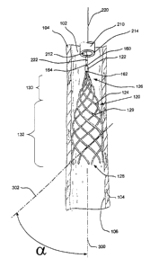
Figures 2 and 3 are plan views of a thrombus filter 120 disposed in a lumen
102 of a blood vessel 100. Blood vessel 100 includes walls 104 which define
lumen
102. Walls 104 of blood vessel 100 include a thin inner membrane referred to
as an
endothelium or an intima 106. The main components of thrombus filter 120 are a
body member or apex 122 and a plurality of elongated wires 124.
The term "wire", as used in describing wires 124 should not be mistaken as
limiting wires 124 to elements having a circular cross section. The cross
section of
6
CA 02382829 2002-02-25
WO 01/17457 PCT/US00/40811
wires 124 may be any number of shapes. For example, wires 124 could have an
oval
shaped cross section. Likewise, the term "wire", as used in describing wires
124
should not be mistaken as being limited to metallic materials. In fact, the
"wire"
forming filter 120 may consist of any biocompatable material possessing the
structural and mechanical attributes necessary for filter 120 to remain in the
desired
location and capture thrombi. Thus, both metallic and non-metallic materials
are
suitable. Examples of preferred metallic materials include stainless steel,
tantalum,
gold, and titanium. Wires 124 may also include a nickel-titanium alloy known
in the
art as Nitinol. Nitinol is commercially available from Memry Technologies
(Brookfield, Conneticut), TiNi Alloy Company (San Leandro, California), and
Shape
Memory Applications (Sunnyvale, California). Preferred non-metallic materials
may
be selected from the list immediately below, which is not exhaustive:
poly(L-lactide) (PLLA), poly(D,L-lactide) (PLA), polyglycolide (PGA),
poly(L-lactide-co-D,L-lactide) (PLLA/PLA), poly(L-lactide-co-glycolide)
(PLLA/PGA), poly(D, L-lactide-co-glycolide) (PLA/PGA), poly(glycolide-co
trimethylene carbonate) (PGA/PTMC), polyethylene oxide (PEO), polydioxanone
(PDS), polycaprolactone (PCL), polyhydroxylbutyrate (PHBT), poly(phosphazene),
polyp,L-lactide-co-caprolactone) (PLA/PCL), poly(glycolide-co-caprolactone)
(PGA/PCL), polyanhydrides (PAN), poly(ortho esters), poly(phoshate ester),
2o poly(amino acid), poly(hydroxy butyrate), polyacrylate, polyacrylamid,
poly(hydroxyethyl methacrylate), polyurethane, polysiloxane and their
copolymers.
In the embodiment of Figure 2, body member or apex 122 is generally
cylindrical in shape. Body member 122 includes a proximal portion 160 and a
distal
portion 162. A coupling member 164 is fixedly attached to proximal portion 160
of
body member 122. It should be understood that further embodiments of body
member 122 are possible without departing from the spirit or scope of the
present
invention. For example, body member 122 could include a bore adapted to
receive a
guide wire or a wire hook.
Wires 124 each have a joined end 126, a free end 128, and an outer surface
129 extending from the joined end 126 to the free end 128. Joined end 126 of
each
wire 124 is fixedly attached to distal portion 162 of body member 122. Each
wire 124
radiates away from body member 122 along a generally helical path of expanding
7
CA 02382829 2002-02-25
WO 01/17457 PCT/US00/40811
diameter. The shape of each wire 124 may be generally described as a spiral,
or a
helix of expanding diameter.
Wires 124 extending outward from body member 122 form a generally conical
filtering portion 130. As mentioned previously each wire 124 follows a spiral
or
helical path. When filtering portion 130 is viewed axially as shown in Figure
3 it has
the appearance of a plurality of spirals. As is also seen in Figure 3,
filtering portion
130 includes a plurality of open cells 134 defined by wires 124.
Open cells 134 allow blood to flow through thrombus filter 120, while wires
124 enable filtering portion 130 to trap, or capture blood clots. The conical
shape of
to filtering portion 130 urges captured blood clots toward the center of the
blood flow.
The flow of blood around the captured blood clots allows the body's natural
lysing
process to dissolve the clots.
As best seen in Figure 2, wires 124 extend beyond filtering portion 130 into a
wall engaging portion 132. When wires 124 contact walls 104 of blood vessel
100,
is they conform to the generally cylindrical shape of lumen 102. As shown in
Figure 2,
wall engaging portion 132 of thrombus filter 120 is generally cylindrical in
shape
when it is positioned in blood vessel 100.
Once thrombus filter 120 has been placed in the desired position by a
physician, it is undesirable for thrombus filter 120 to migrate to another
position in
2o the vasculature of a patient. If a filter becomes loose in the lumen of a
blood vessel, it
may migrate to a position where it does not effectively capture thrombi.
Alternately,
and more seriously, a loose thrombus filter may migrate to a dangerous or life
threatening position. Many prior art filters have addressed this concern by
including
anchor members which penetrate the vessel walls. The use of anchor members
results
25 in significant disruption to the intima of the blood vessel.
Wires 124 of thrombus filter 120 are spring biased outward, so that wires 124
exert an outward force on walls 104 of blood vessel 100 proximate wall
engaging
portion 132. The outward force applied to walls 104 of blood vessel 100 helps
prevent thrombus filter 120 from leaving it's desired position.
3o As described previously, each wire 124 is generally helical or spiraled in
shape. The shape of wires 124 causes them to travel across wall 104 of blood
vessel
100 at an acute angle relative to the longitudinal axis of lumen 120. The
cross-ways
8
CA 02382829 2002-02-25
WO 01/17457 PCT/US00/40811
engagement of wires 124 with wall 104 of blood vessel 100 is best illustrated
in
Figure 2. In Figure 2, the longitudinal axis of lumen 120 is represented by a
first
centerline 300. A second center line 302 is positioned over a portion of a
wire 124
which is engaging wall 104 of blood vessel 100. Second centerline 302 is
aligned
with the centerline of one wire 124. First centerline 300 and second
centerline 302
intersect each other at an angle a. In Figure 2, angle a represents the acute
angle at
which wires 124 engage walls 104 of blood vessel 100.
In a preferred embodiment of thrombus filter 120 angle a is between about
30° and about 90°.
to In a most preferred embodiment of thrombus filter 120 angle a is between
about 80° and about 90°.
Those of skill in the art will appreciate that the angle of helix may vary
from
the filter's apex to the base. For example, the angle may be closer to
30° in the
filtering portion and may be closer to 90° in the wall engaging portion
of the
thrombus filter. The cross-ways path taken by wires 124 as they engage walls
104 of
blood vessel 100 helps retain thrombus filter 120 in the desired position. The
cross
ways engagement between wires 124 and walls 104 serves to prevent thrombus
filter
120 from migrating along the length of blood vessel 100.
As can also be seen in Figure 2, wires 124 engage walls 104 along a
2o significant portion of their length. The significant length of engagement
between
each wire 124 and wall 104 of blood vessel 100 also serves to retain thrombus
filter
120 in the desired position, preventing it from migrating along the length of
blood
vessel 100.
The length of blood vessel 100 in which wires 124 engage wall 104 of blood
vessel 100 may be referred to as the wall contact length. In a presently
preferred
embodiment, the wall contact length is between about 2 cm and about 6 cm. In a
presently most preferred embodiment, the wall contact length is between about
2 cm
and about 3 cm.
The overall length of the filter when it is disposed in blood vessel 100
measured along the longitudinal axis of blood vessel 100 may be referred to as
the
overall filter height. In the presently preferred embodiment, the overall
filter height is
9
CA 02382829 2002-02-25
WO 01/17457 PCT/LTS00/40811
between about 4 cm and about 8 cm. In a presently most preferred embodiment,
the
overall filter height is between about 5 cm and about 6 cm.
As described immediately above, each wire 124 is in continuous contact with
intima 106 of blood vessel wall 104 across a substantial portion of its
length. The
relatively large area of this contact minimizes disruption to intima 106 due
to the
presence of thrombus filter 120. The disruption to intima 106 is minimized
because
the engagement force applied by the thrombus filter is disposed across the
large
contact area. Minimizing the disruption to intima 106 serves to minimize the
amount of endothelial growth resulting from the presence of thrombus filter
120 in
lumen 102 of vessel 100. Minimizing endothelial growth makes the removal of
thrombus filter 120 less problematic. However, thrombus filter 120 may be
removed
even in cases where endothelial growth has occurred.
It is a desirable feature of thrombus filter 120 that wires 124 be shaped so
that
they can be pulled through encapsulating endothelial growth, if such growth
occurs.
In a currently preferred embodiment, the cross sectional dimensions of wire
124 are
substantially unchanged along the entire length of each wire 124. In this
preferred
embodiment, the cross sectional dimensions of wire 124 proximate free end 128
are
substantially the same as the cross sectional dimension of wire 124 in areas
between
fixed end 126 and free end 128. In an alternate embodiment, wires 124 may be
tapered so that each free end 128 is generally smaller than other portions of
the wire
124. The shape of each wire 124 proximate it's free 128 aids in pulling the
wire 124
through any endothelial growth which may occur.
As described previously, each wire 124 is generally in the shape of a helix of
expanding diameter. The gently curved shape of this helix also aids in pulling
wires
124 through any endothelial growth which may occur.
Although thrombus filter 120 is retained securely in place as described above,
it may be removed using minimally invasive methods when such removal becomes
desirable. Referring again to Figure 2, a catheter 210 is shown which may be
used to
remove thrombus filter 120 from lumen 102 of blood vessel 100. The design of
3o thrombus filter 120 allows it to be removed using minimally invasive
methods
without complications due to neointimal hyperplasia or endothelial growth .
CA 02382829 2002-02-25
WO 01/17457 PCT/US00/40811
Catheter 210 includes a distal portion 214 and a lumen 212. Catheter 210 is
made to enter the patients vascular system at a point which is readily
accessible to the
physician. Once in the vascular system, catheter 210 is urged forward until
distal
portion 214 is proximate thrombus filter 120. For example, if thrombus filter
120 is
located in the inferior vena cava of a patients vascular system, catheter 210
may enter
the vascular system at the femoral vein. Alternately, if thrombus filter 120
is located
in the superior vena cava of a patients vascular system, catheter 210 may
enter the
vascular system at the jugular vein. In either case, the filter removal
procedure is
minimally invasive, and does not require general anesthesia.
1o An elongated retrieval member 220 is disposed in lumen 212 of catheter 210.
Retrieval member 220 includes a distal end 222 and a proximal end 224 (not
shown).
Retrieval member 220 is capable of forming a mechanical link with coupling
member
164 of thrombus filter 120. In the embodiment of Figure 2 a mechanical link is
formed by threading a hood through an eyelet. In should be understood that a
number
of methods for forming a mechanical link are known in the art, any of which
may be
used without deviating from the spirit and scope of this invention.
Proximal end 224 of elongated retrieval member 220 protrudes beyond the
proximal end of catheter 210. Both catheter 210 and retrieval member 220
extend
outside the body of the patient. After a mechanical link is formed between
retrieval
2o member 220 and coupling member 164, thrombus filter 120 may be pulled into
lumen
212 of catheter 210 by applying a twisting and pulling force to proximal end
224 of
retrieval member 220. This twisting and pulling force is transferred via
retrieval
member 220 to thrombosis filter 120, "unscrewing" it from the endothelial
growth.
Pulling thrombus filter 120 into lumen 212 of catheter 210 causes wires 124 to
collapse. The collapse of wires 124 causes thrombus filter 120 to assume a
shape
similar to that of lumen 212 of catheter 210. Once thrombus filter 120 is
pulled into
lumen 212 of retrieval catheter 210, the removal of thrombus filter 120 from
the
patient's body becomes a simple matter of withdrawing catheter 210 from lumen
102
of blood vessel 100.
3o Numerous advantages of the invention covered by this document have been
set forth in the foregoing description. It will be understood, however, that
this
disclosure is, in many respects, only illustrative. Changes may be made in
details,
11
CA 02382829 2002-02-25
WO 01/17457 PCT/US00/40811
particularly in matters of shape, size, and arrangement of parts without
exceeding the
scope of the invention. The inventions's scope is, of course, defined in the
language
in which the appended claims are expressed.
12