Note: Descriptions are shown in the official language in which they were submitted.
CA 02382876 2004-11-26
COMPOSITE EXPANSION JOINT MATERIAL
BACKGROUND OF THE INVENTION
1. Field of the Invention
This invention relates, primarily, to composite expansion joint materials for
high
temperature service, i.e., conditions where gas temperatures exceed
600°F.
2. Description of the Prior Art
Early examples of high temperature composite expansion joint materials are
described
in U.S. Patent Nos. 5,296,287 and 5,496,628 (Ribbans). Such materials
typically comprise a
non-fluoropolymer thermal barrier (woven fiberglass mat) laminated to a fluid
barner
(fluoropolymer film) andlor a load bearing composite (fluoropolymer coated
fiberglass fabric).
Lamination is typically effected by melt bondable adhesives, e.g. PFA, FEP,
MFA, etc.
Although the performance of such products was excellent, their widespread
acceptance
by the industry was somewhat hampered by their high costs, due in part to the
high cost of the
woven fiberglass mats used as the thermal barrier components.
Equally efficient and far less expensive nonwoven "needled" fiberglass mats
were
available, but their use was discounted due to the then perceived difficulty
of effectively
coating such high porosity materials with melt bondable adhesives. The
adhesives would
simply "wick" into the needled mats, with insufficient adhesive remaining at
the lamination
interface to effect an adequate bond with the mating component.
This problem was eventually solved by the introduction of the so call "glue
sheet", an
adhesive coated Garner element of the type described in U.S. Patent No.
5,368,923 (Tippett).
The adhesive carrer sheet comprised a light weight scrim coated with the melt
bondable
adhesive, typically PFA. During lamination, the adhesive remained locally
confined at the
lamination interface, resulting in an effective bonding without adhesive loss
through wicking
into the porous needled mat. Although highly successful in this regard, the
relatively high cost
of the adhesive Garner sheet continued to be a drawback.
Accordingly, the objective of the present invention is to overcome the above
described
problems and associated drawbacks by providing an improved lower cost high
temperature
composite expansion joint material in which the needled fiberglass mat is
bonded to a fluid
barrier component and/or a load bearing component by a surface coating of a
fluoropolymer
CA 02382876 2004-11-26
2
based dispersion. The surface coating is selectively applied to a depth which
is less than the
overall mat thickness, thereby efficiently conserving adhesive material while
avoiding
excessive penetration and resulting unwanted stiffness.
A companion objective of the present invention is to improve the resulting
bond while
further restricting adhesive penetration by densifying the needled fiberglass
mat as a
preparatory step to lamination with the other components of the composite.
BRIEF SUMMARY OF THE INVENTION
According to an aspect of the present invention, there is provided a method of
preparing
a single membrane high temperature insulation material, the method comprising:
densifying a
nonwoven insulation mat by reducing its thickness by about 5-50% to provide a
densified mat;
coating a surface of the densified mat with a fluoropolymer based dispersion
to provide a
densified and coated mat, the coating having a depth of penetration which is
less than the total
reduced thickness of the densified mat; and laminating the coated and
densified mat to a
fluoropolymer containing component under conditions of elevated temperature
and pressure.
According to another aspect of the present invention, there is provided a
method of
preparing a single membrane high temperature insulation material, the method
comprising:
coating a surface of a nonwoven insulation mat with an unsintered
polytetrafluoroethylene
based dispersion, the coating having a depth of penetration which is less than
the total thickness
of the mat; laminating in a first step an unsintered polytetrafluoroethylene
film to one side of a
load bearing component under conditions of elevated temperature and pressure;
and laminating
in second step the coated surface of the insulation mat to the
polytetrafluoroethylene film
surface of the laminated component under conditions of elevated temperature
and pressure,
resulting in the coating and the film being sintered.
These and other features and advantages of the present invention will
hereinafter be
described in greater detail with reference to the accompanying drawings,
wherein:
BRIEF DESCRIPTION OF THE DRAWINGS
Figures lA and 1B are plan views respectively of a virgin needled fiberglass
mat and a
needled fiberglass mat following its densification in accordance with the
present invention;
Figure 2 is an exploded cross-sectional view of the components of a composite
expansion joint material in accordance with the present invention;
CA 02382876 2002-02-25
WO 01/19610 PCT/US00/23987
3
Figure 3 a cross-sectional view showing the components of Figure 2 following
lamination under conditions of elevated temperature and pressure;
Figure 4 is a cross sectional view of another embodiment incorporating an
additional load bearing component for added strength; and
Figure 5 is an exploded cross-sectional view of the components of still
another
embodiment of the invention.
DETAILED DESCRIPTION OF THE INVENTION
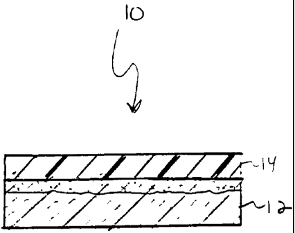
With reference initially to Figure 2, the components of one embodiment of a
composite high temperature expansion joint material of the present invention
include a
nonwoven fiberglass mat 12 coated as at 13 with a fluoropolymer dispersion,
and a
fluid barrier 14. Figure 3 shows the same components after they have been
laminated
under conditions of elevated temperature and pressure. If the strength of the
resulting
laminate is inadequate for certain applications, as shown in Figure 4, a load
bearing
component 16 can be added to the laminated composite.
The needled fiberglass mat is advantageously densified to reduce its thickness
by 5 to SO%. Figures lA and 1B show the fiberglass mat 12 before and after
densification, respectively. The densification process increases the
uniformity of
thickness of the rnat and flattens the mat's surface. The surface of the
densified mat is
thus more susceptible to being evenly coated by the fluoropolymer dispersion,
and its
increased density serves to resist wicking of the dispersion into its
interior.
The mat.12 is densified under conditions of elevated temperature and pressure
by compressing it between heated platens. The mat 12 is densified at a
temperature
between 200 and 900 °F and preferably at a temperature of approximately
725°F. The
operating pressures are between about 5 to 100 psi and preferably at
approximately 40
psi. Cycle time is between 20 and 150 seconds and preferably approximately 75
seconds. The densification process "cleans" the fiberglass by burning off
chemicals in
the fiberglass. The resultant densified mat has a much greater internal
strength than
the virgin needled fiberglass mat.
The fluoropolymer dispersion may include of PTFE, FEP, PFA, MFA, as well
as mixtures and blends thereof, and may further include fluoroelastomers, and
perfluoroelastastomers. The preferred fluoropolymer dispersion is PTFE based
and is
thixotropic .
CA 02382876 2004-11-26
4
The PTFE coated fiberglass mat 12 is laminated to the fluid barner 14 under
conditions
of elevated temperature and pressure. Temperatures range between 660 and 900
°F, with the
preferred temperature being approximately 725 °F. Pressures range
between 1 and 100 psi, with
a pressure of approximately 40 psi being preferable. Lamination cycle time
ranges between 5
and 240 seconds, and preferably is approximately 90 seconds. In the laminate,
there is a
mechanical bond between the coating and the mat and an intermolecular bond
between the
coating and the film.
The application of the fluoropolymer dispersion should be carefully controlled
and
localized at the surface of the mat, with penetration being adequate to
achieve the desired bond,
yet limited to a depth which does not unduly increase mat stiffness.
Penetration depths should
range between 0.001 and 0.125 inches, with the preferred depth being between
0.002 and 0.50
inches. In any event, penetration depth should not exceed 50% of the overall
mat thickness.
The depth of penetration of the fluoropolymer dispersion is dependent on a
number of
factors, including the density of the mat 12, the viscosity of the dispersion,
the specific gravity
of the dispersion, the coating method and its corresponding parameters such as
coating time,
etc.
A fluoropolymer dispersion will be chosen based on the characteristics
required to
produce the desired product. The specific dispersion selected must have
sufficient penetration
to create an adequate bond between the fiberglass mat and its associated
component.
Dispersions having a wide range of viscosities can be utilized dependent on
the thickness and
porosity of the mat, the desired weight of the finished product, the stiffness
of the finished
product, etc.
As disclosed, the specific gravity of the dispersion also affects the coating
properties.
The specific gravity of the dispersion should be in the range of between 1.05
and 1.5 and
preferably at least 1.35. Coating weights should be at least 0.5 oz/sq yd and
less than 32 oz/sq
yd. More preferably the coating weight is preferably between 0.5 and 10 oz/sq
yd, with the
optimal weight being approximately 5.0 oz/sq yd.
Fluoropolymers useful in the composite expansion joint material of the present
invention may be selected from those known to those skilled in the art, as
described for
example in U.S. Patent No. 4,770,927 (Effenberger et al.). Commercially
available
fluoropolymer products useful with the present invention include the
following:
CA 02382876 2004-11-26
Perfluoroplastics
PTFE - Daikin-PolyflonTM; Dupont TeflonTM; ICI FluonTM; Ausimont AlgoflonTM
FEP - Daikin NeoflonTM; Dupont TeflonTM
S PFA - Daikin NeoflonTM; Dupont TeflonTM; Ausimont HyflonTM
MFA - Ausimont HyflonTM
Fluoroelastomers
Dupont VitonTM
3M FluorelTM
Ausimont TecnoflonTM
Daikin DaielTM
Asahi Glass AflasTM
Perfinoroelastomers
Dupont KalrezTM
Daikin PerfluorTM
Of the above, PTFE and specifically unsintered PTFE is preferred. PTFE
produces a
good mechanical bond with the surface of the fiberglass mat and an
intermolecular bond with
the fluoropolymer content of the associated fluid barrier or load bearing
component. Also it is
less expensive than many of the other fluoropolymer dispersions.
The fluoropolymers of the present invention may additionally include fillers,
pigments
and other additives, examples of which include titanium dioxide, talc,
graphite, carbon black,
cadmium pigments, glass, metal powders and flakes, and other high temperature
materials such
as sand, fly ash, etc.
The fluid barner component 14 comprise films of PTFE, FEP, PFA or MFA. As
shown
in Fig. 5, the coated fiberglass mat 12 may alternatively be laminated to a
load bearing
component 18 such as TEXCOATTM or to a combination of a fluid barrier
component 14 and a
load bearing component 16 as shown in Figure 4. The load bearing component may
include
fabric substrates, including woven or knitted substrates, produced from
various materials
CA 02382876 2004-11-26
6
including inter alia, fiberglass, amorphous silica, graphite, polyaramides
including KEVLARTM
and NOMEXTM, PBI (polybenzimadazole), ceramics and metal wires, and
combinations
thereof. Fiberglass is the preferred substrate material.
To produce high temperature insulation materials, i.e. those used at
temperatures over
600 °F, the insulation mat fibers should be formed from
nonfluoropolymers and consist of
randomly arranged mechanically interlocked fibers. The nonfluoropolymers may
include
fiberglass, amorphous silica, graphite, polyaramides, polybenzimadazole and
ceramics.
The fiberglass mat may be coated by various techniques employing vertical
coating
towers, spray coaters, reverse roll coaters, roller coaters, horizontal
coaters with doctor blades,
etc.
Alternatively, two lamination steps may be employed in the production of the
15
composite expansion joint material illustrated in Figure 4. Initially, the
insulation mat is
densified as previously discussed, and then coated with an unsintered PTFE
dispersion 13.
A fluid barrier component 14, typically an unsintered PTFE film 14, and a load
bearing
component 16 are laminated under appropriate elevated temperature and pressure
conditions
with the lamination cycle time ranging between 5 and 240 seconds and
preferably being
approximately 60 seconds.
Subsequently, the fluid barner surface of the laminated component is laminated
to the
coated surface of the densified mat, with lamination cycle time ranging
between 5 and 325
seconds, and preferably being approximately 240 seconds.
This two step lamination procedure improves the overall quality of the
insulation
product by ensuring that a sufficient bond is obtained between the fluid
barner component 14
and the load bearing component 16 before completing the final lamination step
of the process.
The following are illustrative examples of composite expansion joint materials
30 in
accordance with the present invention.
Example A
A needled fiberglass insulation mat having a thickness of %2" and a density of
9-11
lbs/cu ft (BGF Mat; BGF Industries, Inc.; Greensboro, NC) was densified
between
CA 02382876 2002-02-25
WO 01/19610 PCT/US00/23987
7
platens heated to 725°F. Densification was carried out at a pressure of
40 psi for 75
seconds. The resulting densified mat, having a thickness of 3/8" and a density
of 13
lbs/cu ft was surface coated on one side with a PTFE dispersion (Algoflon
D60G;
Ausimont USA; Thorofare, NJ) having a specific gravity of 1.35 and a viscosity
of
250,000 cp. Coating weight was 4.89 oz/sq yd with the penetration below the
coated
surface averaging about 0.005". An unsintered PTFE film having a thickness of
0.004" (DeWal Corporation; Saunderstown, RI) was then laminated to the coated
surface of the insulation mat. Lamination was effected between heated platens
at a
temperature of 725°F and a pressure of 40 psi for a cycle time of 90
seconds.
The resulting bond between the PTFE film and the coated insulation mat was
very uniform, essentially free of any significant lamination voids across the
surface of
the lamination specimen. The adhesion bond between the film and needled mat
was
high, exceeding the internal strength of the insulation mat. The insulation
mat tore in
every attempt to separate the insulation component from the bonded PTFE film.
Example B
TEXCOATTM 1400 (Available from Textiles Coated, Inc.; 32 oz/sq yd
fiberglass fabric, Hexcel-Schwebel Corporation, Anderson, SC; coated with
Algoflon
D60G PTFE dispersion to 48 oz/sq yd) was laminated to the coated surface of
the
insulation mat of Example A with a 0.004" PTFE film (DeWal Corporation) placed
in
between. The components were laminated at a temperature of 725°F and
pressure of
40 psi for a cycle time of 135 seconds.
The resulting bond between the three components was very uniform, essentially
free of any significant lamination voids across the surface of the lamination
specimen.
The adhesion bond of the laminate exceeded the internal strength of the
insulation mat.
The insulation mat tore in every attempt to delaminate any of the three
components in
the laminate.
Example C
TEXCOAT~' 300 (Available from Textiles Coated, Inc.; 8.5 oz/sq yd fiberglass
fabric, JPS Industries, Inc., Slater, NC; coated with Algoflon D60G PTFE
dispersion
to 18 oz sq yd) was laminated to the coated surface of the insulation mat of
Example A.
The components were laminated at a temperature of 725°F and pressure of
40 psi for a
cycle time of 135 seconds.
CA 02382876 2002-02-25
WO 01/19610 PCT/US00/23987
8
The resulting bond between the two components was very uniform, essentially
free of any significant lamination voids across the surface of the lamination
specimen.
The adhesion bond of the laminate exceeded the internal strength of the
insulation mat.
The insulation mat tore in every attempt to separate the TEXCOAT~' 300
component
from the bonded mat.
The foregoing description has been limited to a specific embodiment of the
invention.
It will be apparent, however, that variations and modifications can be made to
the
invention, with the attainment of some or all of the advantages. For example
the
insulation material may be used in conjunction with additional components
dependent
on the desired final product. Also, the insulation material may be used in
applications
below 600°F, e.g., to reduce heat loss from flue gas to the
environment. It is the
object of the claims to cover all such variations and modifications as come
within the
true spirit and scope of the invention.
Example D
A needled fiberglass insulation mat having a thickness of'/z" and a density of
9-
11 lbs/cu ft (BGF Mat; BGF Industries, Inc.; Greensboro, NC) was densified
between
platens heated to 725 °F. Densification was carried out at a pressure
of 40 psi for 75
seconds. The resulting densified mat, having a thickness of 3/8" and a density
of 13
lbs/cu ft was surface coated on one side with an unsintered PTFE dispersion
(Algoflon
D60G; Ausimont USA; Thorofare, NJ) having a specific gravity of 1.35 and a
viscosity of 250,000 cp. The coating weight was 4.89 oz/sq yd with the
penetration
below the coated surface averaging about 0.005".
An unsintered PTFE film having a thickness of 0.004" (DeWal Corporation;
Saunderstown, RI) was then laminated to TEXCOAT'~ 1400. The components were
laminated between heated platens at a temperature of 725°F and a
pressure of 40 psi
for a cycle time of 60 seconds to produce a laminated composite.
The coated surface of the insulation mat was then laminated to the film
surface
of the laminated composite. This second lamination step was performed at a
temperature of 725°F and a pressure of 40 psi for a cycle time of 240
seconds.
The resulting bond between the PTFE film and the coated insulation mat was
very uniform, essentially free of any significant lamination voids across the
surface of
the lamination specimen. The adhesion bond between the film and needled mat
was
high, exceeding the internal strength of the insulation mat. The insulation
mat tore in
CA 02382876 2002-02-25
WO 01/19610 PCTlUS00/23987
9
every attempt to separate the insulation component from the bonded PTFE film.
Example E
TEXCOATTM 300 was laminated to the unsintered PTFE coated surface of the
insulation mat of Example D. The components were laminated at a temperature of
725°F and a pressure of 40 psi for a cycle time of 240 seconds.
The resulting bond between the two components and was very uniform,
essentially free of any significant lamination voids across the surface of the
lamination
specimen. The adhesion bond of the laminate was high, exceeding the internal
strength
of the insulation mat. The insulation mat tore in every attempt to separate
the
TEXCOAT''M 300 from the bonded mat.
I claim: