Note: Descriptions are shown in the official language in which they were submitted.
CA 02382934 2002-03-26
WO 01/41971 PCT/GB00/04651
1
COMPUTER CONTROLLED GRINDING MACHINE
Field of Invention
This invention concerns the grinding of workpieces such as crankpins and the
cam regions
of cam shafts, where the grinding wheel performing the grinding is moved
towards and
away from the axis about which the workpiece is rotating so as to maintain
engagement
with the surface thereof which is to be ground, as the workpiece rotates
around its main
axis such as in the case of a crankpin which precesses around the main
crankshaft axis, as
the latter rotates.
Background to the invention
The advance and withdrawal of the grinding wheel is normally under computer
control and
with the current development of grinding machines, errors which hitherto were
present in
ground workpieces have been largely eliminated by appropriate programming and
secondary errors which were previously masked by the larger process errors,
have now
begun to be revealed.
Errors such as out of roundness of 1 or 2 microns, can result in unwelcome
wear of a final
component such as between a crankpin and lower big end bearing.
Errors which have already been accommodated, can arise from the varying height
of the
axis of the workpiece region which is being ground (such as the orbital
movement of a
crankpin as the crankshaft rotates), relative to the horizontal plane
containing the axis
about which the grinding wheel rotates. Typically the throw of a crankshaft is
the order of
a few centimetres and there is thus a considerable variation in height of the
axis of the pin
relative to the horizontal plane containing the wheel axis of rotation as the
pins are rotated
due to the rotation of the crankshaft. The grinding wheel is moved towards and
away from
CA 02382934 2002-03-26
WO 01/41971 PCT/GB00/04651
2
the crankshaft so as to maintain the grinding contact with the surface of the
pin at all times
as the latter is rotated around the main crankshaft axis, but, assuming that
the crankpin
axis lies in the same horizontal plane as the axis of rotation of the grinding
wheel, there
are only two points during each rotation of the crankshaft when the pin axis
also occupies
that same plane. These are at 3 o'clock and 9 o'clock positions. At the 12
o'clock and 6
o'clock positions, the pin axis will be at the maximum displacement above and
below the
plane and at all intermediate positions, the height of the pin will vary
relative to the plane.
The reference to a horizontal plane presupposes that the movement of the
grinding wheel is
in a horizontal sense without any divergence therefrom. This is normally the
case but for
the avoidance of doubt, it is to be understood that if the locus of the
grinding wheel axis as
the latter is moved towards and away from the workpiece, is in a plane which
is not
horizontal, the same considerations still apply with regard to the alignment
of the
crankshaft axis with the wheel axis, except that the "3 o'clock" and "9
o'clock" positions
now correspond to when the crankpin axis lies within the plane containing the
path of the
movement of the wheel axis.
Computer controlled grinding machines have been programmed to alter the
wheelhead
demand positions during the crankpin rotation, to compensate for the errors
which can
result from the varying height of the crankpin as the crankshaft rotates. Such
a machine
will be referred to as "of the type described" .
In the more general case, the main axis of rotation of the crankshaft (or cam
shaft as the
case may be) will not normally occupy the same plane as the path of movement
of the
grinding wheel axis as the latter is moved towards and away from the
workpiece, so that
there is a constant height error to be taken into account. Effectively this
introduces a
degree of non-symmetry into the errors arising during the rotation of the
crankshaft or cam
shaft, which would generally be symmetrical if the workpiece axis and grinding
wheel axis
occupied the same plane as the path of movement of the grinding wheel axis
towards and
away from the workpiece.
1 'rJ''12'2001 CA 02382934 2002-03-26
.. .. ' . .: . . _ . ..,; . . ,
US 4,747,23b discloses a computer controlled grinding machine programmed so as
to
control the machine by calculating the wheelhead d~nand positions so as to
grind the
desired workpiece using appropriate parameters for the workpiece, based on the
asstunption that the workpiece aus and grinding wheel axis occupy i6e same
plane as does
the path of movement of the wheel axis towards or away from the workpiece. See
in
particular Col 1 and 2 and Fig 3. I3owever, the subject matter of claim I
differs thercof in
particular, that for error correction purposes, a demand position value is
computed which
also takes into account the difference in height between the workpiece axis of
rotation ~d
the grinding wheel axis of rotation.
However, there is nothing in US 4,?47,236 which teaches one how to overcome
die
problem which occurs wlxn grinding a workpiece which moves vertically relative
to the
wheel axis such as when grinding a crank pin of a crankshaft when the laacr is
rotated
about a main axis. Here a cons~tamt height error occurs, since the main aus
of.rotation of
tl~ crankshaft will not ~nnally occupy the same plane as the path of movematt
of the
grindiuig wheel aus as the latter moves relative to the workpiece. This fact
introduces
effectively a degree of noa-symmeay, resulting in imprecise grinding
operations.
Us 4,747,236 also discloses a method of co~ruter controlled grinding (tee Col
1, In 54)
but no steps are provided to correct demand position values taking into
account auy non-
circularity or non-concenaic rotation of the workpiece, wgether with auy
difference in
height between the workpiece and wheel axes.
The problem of griping errors caused by the height variation of the workpiece
relative to
the grinding wheel axis of rotatiowherefore retrains.
AMENDED SHEET
CA 02382934 2002-03-26
WO 01/41971 PCT/GB00/04651
3
It is an object of the present invention to provide a solution to this
problem.
Summary of the Invention
According to the present invention in a computer controlled grinding machine
programmed
so as to control the machine by calculating the wheelhead demand positions so
as to grind
the desired workpiece using appropriate parameters for the workpiece such as
roundness,
diameter, throw and taper (if required) based on the assumption that the
workpiece axis
and grinding wheel axis occupy the same plane as does the path of movement of
the wheel
axis towards and away from the workpiece, wherein the machine is also
programmed to
alter the wheelhead demand position during workpiece rotation to compensate
for errors
resulting from the varying height of the workpiece as the latter rotates, and
wherein a
demand position value is computed which takes into account the difference in
height
between the workpiece axis of rotation and the grinding wheel axis of rotation
for each of
a plurality of rotational positions of the workpiece around its axis and
stored for each
position, prior to grinding, and the wheelhead position demand signals
employed during
grinding of the workpiece are derived from the stored values.
If the difference in height between a crankshaft workpiece axis and the wheel
axis is H,
then in accordance with the invention, the demand position value (P) for each
angular
position of the workpiece A (measured in the direction of rotation of the
workpiece around
its main axis from a start position) is given by the following equation:-
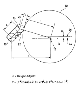
P=(T* cos A) + ~ (R+r)' - ((T* sin A) + H)2) (1)
Where:- R is the current radius of the grinding wheel,
r is the target radius for the crankpin, and
T is the throw of the crankpin around the main crankshaft axis.
Typically the grinding wheel rotates in one sense, e.g. clockwise, and the
crankshaft
rotates in the opposite sense, e.g. anti-clockwise, and the start position is
when the
CA 02382934 2002-03-26
WO 01/41971 PCT/GB00/04651
4
grinding wheel is at its furthest (most rearward) position relative to the
crankshaft axis,
and the crankpin and crankshaft axes occupy the same horizontal plane.
Typically the computed value for P is calculated for each of 3600 positions
during one
revolution of the workpiece, ie from A= 0 to 2~c (which in the case of a
rotating
crankshaft results in turn in one revolution of the crankpin about its axis).
Preferably during grinding of the crankpin, the value for P is calculated at
each of a
succession of equally spaced apart points in time from the beginning of the
grind, by using
the appropriate value for P from the stored values of P, or where the angular
position of
the workpiece at any instant does not correspond precisely with an angular
position at
which a value for P has been stored, a value for P is computed by
interpolating between
the two adjoining stored values for P.
It has been found that a 0.1 millimetre height discrepancy H can result in a 1
micron
roundness error, ie a 1 micron necking of what should otherwise be a circular
cross-
section.
The invention also lies in a computer controlled grinding machine as aforesaid
in which the
computer is loaded with a program and operated to calculate and store in a
memory the
demand position (P) for the wheelhead using and equation for (P) taking
account of any
non-circularity or non-concentric rotation of the workpiece, together with any
difference in
height between the workpiece and wheel axes, for each of a plurality of
positions during
one revolution of the workpiece, and the wheelhead feed is subsequently
controlled by
signals derived from the stored values of (P), during a subsequent grinding of
the
workpiece.
The invention also lies in a method of controlling the wheelhead of a computer
controlled
grinding machine so as to accommodate errors which would arise due to
misalignment of
the horizontal planes containing the wheel axis and the main axis about which
the
workpiece is rotated; wherein as a first step, a computer is loaded with a
program which
CA 02382934 2002-03-26
WO 01/41971 PCT/GB00/04651
enables the instantaneous demand position for the wheelhead (P) to be
calculated for each
of N positions of the workpiece for a single revolution of the workpiece, and
storing the
computed value of (P), and as a second step, during grinding of the workpiece,
computing
the demand position for the wheelhead at each of a succession of equally
spaced apart
points in time from the start of grinding, by relating the time to the angular
position of the
workpiece and using the N stored values and interpolating between them where
values for
P required are intermediate the values stored for particular angular
positions, and as a third
step generating a demand position control signal for controlling the wheelhead
during
grinding using the stored and/or interpolated demand position values for P.
Preferably in the above method the value of P is recalculated at lms intervals
during the
grinding.
The invention also lies in workpieces when ground using a grinding machine as
aforesaid
or a grinding machine operating in accordance with the above method.
The invention will now be described by way of example with reference to the
accompanying drawing which illustrates in side elevation, a grinding wheel and
crankpin
workpiece.
In the drawing the grinding wheel 10 rotates about axis 12 and is mounted for
fore and aft
movement along path 14 to allow the wheel to engage and disengage a workpiece
and in
the case of an eccentric component such as a crankpin, to allow the wheel to
follow the
orbital path of the pin and maintain grinding engagement between wheel and
pin, as the
crankshaft containing the pin, itself rotates.
In the drawing, the main axis of the crankshaft is denoted by 16, and the pin
being ground
is denoted by 18, with its axis shown at 20.
The pin 16 is situated at the outboard end of a pair of crank-arms one of
which is shown at
22.
CA 02382934 2002-03-26
WO 01/41971 PCT/GB00/04651
6
The path 14 generally will be horizontal and ideally the crankshaft axis
should lie in the
same horizontal plane as the wheel axis 12 and path 14.
In the general case, for many different reasons, this will not be the case,
and the
perpendicular distance between the plane 24 (containing the wheel axis 12 and
path 14) and
the horizontal plane 26 containing the crankshaft axis 16, is identified by H.
In accordance with the invention, the demand position for the wheel 10 at each
of a
number of rotational positions of the crankshaft is computed prior to.the
commencement of
grinding using the formula (2) above. The start position (where A=0) is where
the
straight line joining the crankshaft axis 16 and the pin axis 20 lies in the
horizontal plane
26, with the pin 18 between the crankshaft axis 16 and the wheel 10.
During grinding, the crankshaft is rotated relatively slowly about its axis 16
so that in turn
the crankpin is rotated around the crankshaft axis 16, while the wheel 10
rotates around its
axis 12 at a relatively high speed, typically many thousands of revolutions
per minute, and
is advanced and retarded relative to the crankshaft so as to remain in contact
with the pin
in manner known per se.
In a preferred arrangement the demand position P is computed for 3600 equally
circularly
spaced positions of pin 18 around crankshaft axis 16, for a single rotation of
the crankshaft
between A=0 and A=360° (ie P is recalculated every 1/10° of a
degree of rotation of the
crankshaft) before grinding of the pins commences. During grinding at 1 msec
intervals
from the start of the grind, a value for P is computed by interpolating
between the stored
pre-calculated values, dependent in the angle A at each instant. The
interpolated values for
P are used to determine the signals required to determine the demand position
for the
wheelhead, using equation (1) above.