Note: Descriptions are shown in the official language in which they were submitted.
CA 02383022 2002-04-22
Prssby-Tyson 97-8
METHOD AND APPARATUS FOR THE CORRECTION OF OPTICAL SIGNAL
WAVE FRONT DISTORTION WITHIN A FREE-SPACE OPTICAL
COMMUNICATION SYSTEM
Field of the Invention
The present invention is related generally to data communication systems
and, in particular, to free-space optical data communication systems.
to Background of the Invention
Telecommunication systems that connect two or more sites with physical
wire or cable are generally limited to relatively low-speed, low-capacity
applications. Laying the cable for such systems is also expensive and may be
difficult, especially in congested metropolitan areas where installation
options are
~s limited. In order to address these limitations, recently developed systems
utilize
the free-space transmission of one or more light beams modulated with data to
transmit the data from one point to another. Even in the case where a
physical,
hard-wired connection between two networks exists, a free-space system using
such beams provides a higher-speed and higher-capacity fink, presently up to
10
2o Gbps, between these networks. When two networks are not already physically
linked via wire, free-space communication avoids the communication system
infrastructure cost of laying cable to connect one site in the system to
another.
Instead of cables, free-space optical communications systems comprise, in
part,
at least one transmit telescope and at least one receive telescope fior
sending
CA 02383022 2002-04-22
Presby-Tyson 97-8
and receiving information, respectively, between two or more communications
sites.
The operation of free-space optical communications may be hampered by
a variety of factors, however. For example, distortion of the wave front of
the
s transmitted light beam may occur due to turbulence, attenuation, or other
phenomena. This distortion may result in a phenomenon known as "beam tilt"
wherein different discrete sections of the wave front of the beam deviate from
their transmitted, orthogonal orientation to the line of travel of the beam.
At the
receive telescope, the result of such beam tilt is the movement of the image
of
to the received beam on the focal plane of the receive telescope. Beam
intensity
fluctuation, also known as scintillation, rnay also occur. Either of these
phenomena may result in significant degradation or total loss of
communications.
Summary of the Invention:
is The aforementioned problems related to wave front distortion are
ameliorated by the present invention. In accordance with the present
invention,
the optics of the receive telescope are manipulated using adaptive optics to
compensate for at least some of that distortion. The term "adaptive optics,"
as
used heroin, means an optical system in which at least one optical parameter
is
2o varied as a tunc~ion of a control signal, such as a signal indicative of
phenomena
that distort the wave front of the transmitted signal. An example of optics
suited
for use in such a system, and used in the illustrative embodiment disclosed
herein, is the defomlable mirror described in the co-pending patent
application
-2-
CA 02383022 2002-04-22
Presby-Tyson 97-8
titled "Telescope For A Free-Space Wireless Optical Communication System,"
having Serial No. 09/879159. Wave front distortion is manifested at the
receive
telescope as a deviation from the normal, orthogonal orientation of the wave
front
of the transmitted light beam relative to its line of travel. This deviation
may be
s detected, for example, by a wave front sensor, such as a Shack-Hartman
sensor,
which identifies the slope, or beam tilt, of discrete sections of the
transmitted
beam. The optics of the receive telescope can then be deformed in such a way
as to cancel the wave front distortion and correspondingly reduce the
resulting
distortion of the received signal.
to The use of adaptive optics in a receive telescope to correct for distorted
signals is welt known in astronomy, for example. However, there are key
differences between the use of adaptive optics in astronomy and the use of
adaptive optics in telecommunications, per the present invention. These
differences are such as to lead those in the art from considering the use of
~s adaptive optics for telecommunications applications. For example,
telescopes
used in telecommunications tend to be of much smaller aperture than those used
in astronomy. Thus, a given defom~ation of a given magnitude on the
telecommunications telescope would have a much greater effect on the signal
characteristics than would the same deformation on an astronomical telescope.
2o As a result, correction of such deformations requires a much wider range of
dynamic control of the optics of telecommunications telescopes than for
telescopes in astronomical uses. Additionally, the distances over which the
communications beam travel are much smaller than the distances over which an
CA 02383022 2002-04-22
Presby-Tyson 97-8
astronomical beam of light travels. However, whereas astronomical light beams
travel essentially perpendicular relative to stratified atmospheric
distortion, a
communications beam as used in the present invention is nearly tangent to
those
layers. The distortion is therefore of a different nature than that
encountered in
s astronomy. Specfically, beams used in communications are exposed to a
qualitatively different power spectrum of wave front distortions than are
astronomical light beams. Thus, the desirability of using adaptive optics to
correct for this distortion has not been apparent.
Finally, one can vary the characteristics of transmitted signals in
io telecommunications in a way that, obviously, is impossible in astronomical
uses.
Thus, most prior art efforts to minimize effects of distortion in
telecommunications
systems have focused on actively manipulating the transmitted signal by, for
example, increasing or decreasing its amplitude. Therefore, while the concept
of
adaptive optics in n3cent telescopes is well known, it remained for the
present
~s applicants to realize the utility and applicability of adaptive optics to
the
telecommunications realm.
Brief Description of the Drawing
FIG. 1 shows an optical communication system using a prior art telescope
2o apparatus during normal communications conditions;
FIG. 2 shows an optical communication system using a prior art telescope
apparatus wherein atmospheric turbulence causes wave front distortion of a
transmitted beam;
-a-
CA 02383022 2002-04-22
Presby-ryso~ s~-s
FIG. 3 shows a receive telescope in the system of the present invention
that is capable of being deformed using adaptive optics to compensate for
atmospheric turbulence;
FIG. 4 shows an optical communication system utilizing adaptive optics in
accordance with the principles of the present invention to compensate for wave
front distortion of the received beam;
FIG. 5 shows a Shack-Hartman sensor that is capable of determining the
slope of discrete sections of the wave front of the received beam to determine
the effects of atmospheric turbulence on the beam;
io FIG. 6A shows a cross-section of a charge-coupled device utilized in the
sensor of FIG. 5 and the images produced thereupon when there is no
atmospheric turbulence;
FIG. 6B shows a cross-section of a charge coupled device utilized in the
sensor of FIG. 5 and the images produced thereupon when atmospheric
is turbulence is present; and
FIG. 7 shows a flow shark depicting illustrative steps of the operation of the
system of F1G. 4.
Detailed Descrlptlon of the Invention
2o FIG. 1 shows two prior art optical communication telescopes, 101 and
102, during normal aligned operating conditions in a freo-spaoe optical
communications system. Laser 130 produces a light beam that is modulated by
modulator 131 with data received from network 110 and transmitted on optical
-s-
CA 02383022 2002-04-22
Presby-Tyson 97-8
fiber 106. The transmit telescope 101 receives the modulated optical signal
via
optical fiber 108. Primary mirror 120 and secondary mirror 121 of telescope
101
optically shape and transmit the modulated light beam such that the beam is
incident upon the focal plane 125 of receive telescope 102. Receive telescope
s 102 utilizes its optics, including a primary mirror 122 and a secondary
mirror 123,
to focus the incident transmitted modulated light beam 103 onto the receive
optical fiber 112 at the focal plane 125. Receiver 129 receives the modulated
optical signal from the receive optical fiber and converts it to an electrical
signal,
demodulates the data, and forwards the data to network 109. It should be noted
to that receive telescope 102 may be made capable of transmitting a light beam
by
incorporating a laser and a modulator similar to laser 130 and modulator 131.
Likewise, the transmit telescope 101 may be made capable of receiving by
incorporating a receiver into the electronics of that te~pe, similar to
receiver
129. Thus, both telescopes of the system wou~ be capable of transmitting and
is receiving. Such a dual-use capability of transmitting and receiving is
intended to
apply to all telescopes described in the embodiments of the present invention
disclosed hereinafter.
In certain situations, the wave front of tl~e light beam transmitted by a
transmitting telescope may be distorted when ~ arrives at the focal plane of
the
2o receive telescope, resutGng in a correspondingly distorted communications
signal. As shown in FIG. 2, such distortion may occur due to atmospheric
turbulence, such as small-cell turbulence 204, anywhere al~g the path between
telescopes 201 and 202, that causes portions of the wave front of the
transmitted
CA 02383022 2002-04-22
Presby-Tyson 97-8
beam 203 to refract and thus deviate from the direct path between the transmit
and receive telescopes. When this occurs, discrete portions of wave front 205
become non-orthogonal to the line of travel 207 of the wave front. The result
is
that certain portions of the wave front will arrive at the receive telescope
at
different times than others and may arrive at different angles relative to the
line of
travel of the beam 207. Thus, the apparent position of the transmit telescope
will
change relative to the receive telescope, which changes the location of
discrete
portions of the image of the received beam on the focal plane of the receive
telescope. The image on the focal plane of the receive telescope may also vary
lo in intensity over time resulting in variations in the received power of
discrete
portions of the received beam. 'this can significantly degrade communications
between the two telescopes.
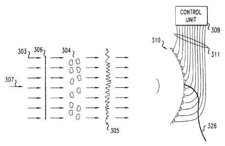
FIG. 3 shows one embodiment of the present invention that addresses the
aforementioned degradation by measuring, for example, the effects of
turbulence
is in the atmosphere on the beam's wave front and compensating for that
turbulence at the receive telescope. In that embodiment, the wave front 306 of
beam 303 is undistorted and is orthogonal to the line of travel 307 of the
beam.
Upon passing through turbulence 304, however, wave front distortion results,
as
exemplified by wave front 305. When received by receive telescope 302, this
Zo distortion is measured, as described below, and the locations on the
primary
mirror of the receive telescope that must be deformed are identified, as well
as
the magnitude and direction of that deformation. Control unit 309 of the
receive
telescope 302 then varies the individual voltages to electrodes 310 located at
or
CA 02383022 2002-04-22
Presby-Tyson 97-8
near the surface of primary mirror 325 via leads 311. By applying a voltage
difference between the mirror 325 and the electrodes 310, an electrostatic
attractive or repelling force is produced between each electrode and a portion
of
the mirror near that electrode, causing the mirror to be deformed. The use of
s such deformable mirrors in free-space laser communications systems is the
subject of the above-cited copending application. Varying the voltages on the
electrodes 310 enables the extent of the deformation of mirror 325 to be
controlled. The result is that the distortion of beam 303 with a received wave
front 305 is compensated for in a way such that the image of the beam incident
to upon receive optical fiber 328 is substantially undistorted and is the
image of a
beam that is orthogonal to the line of travel 307of the beam.
FIG. 4 shows a free-space telecommunications system incorporating the
embodiment of the present invention of FIG. 3 that utilizes adaptive optics,
as
described above, to compensate for disturbances that cause the aforementioned
is distortion. In that system, laser 419 produces a light beam that is
modulated by
modulator 418 with data from network 410. This modulated light beam is then
transmitted to telescope 401 which shapes the beam 403 so that it is incident
on
the focal plane of n~oe'rve telescope 402. Photodetedor 411 detects the
incoming light energy, converts it to an electrical signal, and forvvards it
to
2o receiver 433, which demodulates the signal. The demodulated data is then
forwarded to the intended destination within network 409.
When signal 403 is transmitted from transmit telescope 401, the wave
ftont 406 of that signal is undistorted and all sections of the wave front are
.8_
CA 02383022 2002-04-22
Presby-Tyson 97-8
substantially orthogonal to the line of travel. However, when atmospheric
turbulence 404 is present along the path of signal 403, wave front 406 may
become distorted with portions not orthogonal to the line of travel, as
exemplified
by wave front 405.
When signal 403 reaches the receive telescope 402, beam-splitter 423
splits signal 403 in a way such that signal 424 is incident upon sensor 430,
here
exemplified by a Shack-Hartman sensor. Sensor 430 receives the light beam,
detects the arrival of the wave front 405 and determines whether effects of
distortion of the signal 403, such as that caused by turbulence 404, are
present.
to The Shack-Hartman sensor, which is well known in the art, utilizes an array
of
lenses orthogonal to the transmission path of the beam to isolate discrete
sections of the potentially-distorted wave front 405 and focus images of those
discrete sections onto a charge-coupled device. The sensor then measures the
magnitude and direction of the displacement, if any, of each of those images
is relative to its nominal, calibrated position, i.e., the position of the
image if there
was no distortion of the wave front. The displacement of each image relative
to
its nominal, calibrated position is directly proportional to the phase
deviation of a
corresponding discrete area of the wave front of the received beam. Referring
to
FIG. 5, depicting a Shack-Hartman sensor, the communicatians beam, 403 in
2o FIG. 4, is split such that the beam is incident upon the focal plane of the
receive
telescope and, at the same time, split beam 424 is incident upon lens 502 of
the
Shack-Hartman sensor. Lens 502 refracts beam 424 in such a way that it
causes a portion of a parallel light beam to be incident upon each of the
lenses
CA 02383022 2002-04-22
Presby-Tyson 97-8
504. Lenses 504 focus separate images of segments of the beam onto a
charge-coupled device (CCD) 505. FIG. 6A and FIG. 6B are representations of
the cross section A-A' of CCD 505 in FIG. 5. In the case where no turbulence
is
present in the atmosphere, the images 602 of each portion of the beam will be
s focused on nominal, calibrated positions on the CCD 505. However, when
turbulence 404 in F1G. 4 is present it will distort the orthogonal, planar
wave front
406, resulting in wave front 405. In this case, the sensor will detect images
604
on CCD 505 that are displaced from those nominal, calibrated positions. The
images of the discrete portions of the beam may also be blurred, as
represented
io by images 605. The displacement of the image relative to its nominal,
calibrated
focus point is proportional to the phase deviation of discrete sections of the
wave
front. By calculating each of these deviations, it is then possible to
determine the
shape of the entire wave front.
Referring once again to FIG. 4, using the aforementioned phase deviation
is information, the present invention corrects for atmospheric turbulence 404
by
varying the shape of the primary mirror 422 of the receive telescope 402 to
compensate for the phase deviations caused by turbulence. The result is that
the image of wave front 405 on the focal plane of the receive telescope 422
will
be an image of an undistorted wave front.
2o In order to achieve the aforementioned deformation, control unit 409
receives the
phase deviation data from Shack-Hartman sensor 430 and deforms the primary
mirror of the receive telescope 402 accordingly. To do this, control unit 409
applies a voltage to individual electrodes 410 located near the surface of the
-io-
CA 02383022 2002-04-22
Presby-Tyson 97-8
mirror 422 where deformation is desired. Deformation of the mirror 422 is
varied
by varying the voltages applied to the electrodes 410. In order to pre-
compensate, on an ongoing basis, for distortion of the transmitted signal 403,
the
wave front 405 of the signal 403 is continuously or periodically monitored by
s sensor 430 at the receive telescope 402 for changes to the turbulence
condition
404.
Illustrative steps of the operation of the system of FIG. 4 are shown in FIG
7. An initial communications connectivity signal 403 is generated at step 701
to
determine the effects of distortion on the communications signal. If
distortion is
io present, at step 702, then the system determines which discrete locations
of the
primary mirror of the receive telescope need to be deformed, as well as the
magnitude and direction of deformation required at each discrete location on
that
mirror. At step 703, the primary mirror of the receive telescope is deformed.
Once the system has compensated for the distortion, primary communications
t s begin at step 704. While communications are ongoing, the system
continually
monitors the distortion of the signal, at step 705, for any change that may
necessitate changes to the deformation of the primary mirror. At step 707, if
additional distortion is detected, the invention once again, at step 706,
deforms
the primary mirror of the receive telescope to compensate far the distortion.
2o Then, if the system has successfully compensated for the distortion via the
use of
adaptive optics, primary communications continue at step 708. If the primary
communications period has not ended at step 709, then the system continues to
monitor the signal, at step 705, for any distortion which may arise and
CA 02383022 2002-04-22
Presby-Tyson 97-8
compensate for that distortion as necessary via changing the location and
amount of the distortion of the primary mirror of the receive telescope.
The foregoing merely illustrates the principles of the invention. It will thus
be appreciated that those skilled in the art will be able to devise various
s arrangements which, although not explicitly described or shown herein,
embody
the principles of the invention and are within its spirit and scope.
Furthermore, all
examples and conditional language recited herein are intended expressly to be
only for pedagogical purposes to aid the reader in understanding the
principles of
the invention and are to be construed as being without limitation to such
1o specifically recited examples and conditions. Moreover, all statements
herein
reciting aspects and embodiments of the invention, as well as specific
examples
thereof, are intended to encompass functional equivalents thereof.
Diagrams herein represent conceptual views of optical telescopes and
light beams modulated with data for the purposes of free-space optical
is communications. Diagrams of optical components are not necessarily shown to
scale but are, instead, merely representative of possible physical
arrangements
of such components. Optical fibers depicted in the diagrams represent only
mechanism for transmitting data between telescopes and network destinations.
Any other communication method for passing data from the telescopes to
2o network destinations is intended as an alternative to the method shown in
the
diagram. Also, while the representative embodiment above uses the example of
atmospheric turbulence as a phenomenon that would result in wave-front
distortion, such distortion may result from any number of causes. For example,
if
CA 02383022 2002-04-22
Presby-Tyson 97-8
the light beam passes through any material located in the path of the beam,
such
as window glass, significant wave front distortion could result. The method
and
apparatus of the present invention will at least partially correct for any
wave front
distortion that results for any reason.
Additionally, although the disclosed embodiment uses telescopes 401 and
402 in FIG. 4 for both primary communications purposes as well as for
monitoring wave front distortion on the communications signal, a separate
reference communications system having separate telescopes located near the
primary communications telescopes could be used to obtain the wave front
io deformation information. Methods of adding such a reference system to the
primary communications system will be apparent to those skilled in the art.
Other aspects of the disclosed embodiments of the present invention are
also merely illustrative in nature. For instance, while a Shack-Hartman sensor
is
used to determine the shape of the received wave front in the above-described
Is embodiment, any suitable sensor for determining the effects of wave front
distortion may be used. Such sensors are well known in the art of adaptive
optics. Additionally, although the embodiment presented utilizes traditional
network connections to deliver information to and from the telescopes,
wireless
methods of communication could alternatively be used. In this case, the
2o communications system could use a different wavelength for the feedback
signal
to avoid interfering with the primary communications signal. Also, the
disclosed
embodiment of the present invention electrostatically deforms the primary
mirror
of the receive telescope by varying the voltages applied to electrodes near
the
-13-
CA 02383022 2002-04-22
Presby-Tyson 97-S
surface of that mirror. However, any mirror of the receive telescopes may be
similarly deformed with identicaV results. Deforming any mirror in the
communications system to achieve the same result as in the embodiments of the
present invention will be apparent to one skilled in the art. Also, there are
many
well-known alternatives to the use of electrostatic effects as used herein for
deforming discrete sections of the mirrors, such as piezeo-electric drivers or
mechanical screws. Any method of deforming any mirror in the communications
system is intended to be encompassed by this invention.
Finally, any method of using adaptive optics at the receive telescope to
to compensate for distortion to the wave front is intended to be encompassed
by
the present invention. For example, lenses may be used as the functional
equivalents to mirrors. Additionally, any use of segmented mirrors to deform
the
wave front of the communications light beam is the functional equivalent of
deforming a single mirror in multiple, discrete locations. Instead of using a
is single, continuous primary or secondary mirror to deform the wave front of
the
communications signal, segmented mirrors comprise many small mirrors which
are independently movable to achieve the same effect. Any such method, or its
functional equivalent, is expressly intended to be encompassed by the present
invention disclosed herein.
-14_