Note: Descriptions are shown in the official language in which they were submitted.
CA 02383441 2002-04-24
This invention relates to the cryogenic comminution of rubber and more
particularly
to a process by which scrap rubber can by cryogenically comminuted into a
powder suitable
for use in a variety of applications.
At the present time, very little scrap rubber is recycled because of the
difficulty of
pulverizing or comminuting it to particles of a size that are suitable for
reuse. Scrap rubber
can be cut or shredded into chips of about 2" to 3" in size but, in general,
such chips are not
fine enough for reuse. In most instances, the particles must be in the range
of about 10 to
about 100 mesh ASTM in size to be suitable for reuse.
Because of the difficulty of comminuting scrap rubber, most of it is disposed
of in
land-fill sites. The material is not suited to such disposal because it does
not decompose or
change in composition over time even when mixed with soil or other forms of
manufactured
waste. Furthermore, any buried rubber tends to rise to the surface over time
due to its
inherent dynamic buoyancy.
We have invented a process for the cryogenic comminution of scrap rubber into
a
powder suitable for use in a variety of applications. Briefly our process
involves the steps of
cooling chips of scrap rubber to a temperature in the range of about minus 90
to about minus
110 degrees Celsius; and comminuting the cooled rubber chips to powder
substantially of
a size of less than about 10 mesh ASTM.
The apparatus used to carry out the processes of my invention is described
with
reference to the accompanying drawings in which Figures 1, 2 and 3 are
schematic elevations
of the apparatus used to carry out three variations of the process.
Like reference characters refer to like parts throughout the description of
the
drawings.
1
CA 02383441 2002-04-24
The starting material is chips or small pieces of scrap rubber. The chips or
pieces
should be small enough to pass through a screen having openings of about 2" by
3". The scrap
rubber can be so-called "high-end" rubber from used tires or it can be "low-
end" rubber
consisting of elastomers, EPDM polymers, butyl and other waste from sources
other than
used tires. Such low-end scrap rubber originates from the production of a
multitude of
relatively small rubber parts used in industry and by consumers.
Low-end scrap rubber jams or stalls conventional shredding machines.
Furthermore
such rubber is difficult to grind mechanically because it overheats and
damages the grinding
apparatus. Such rubber can however be easily chipped into small pieces by way
of a
conventional guillotine-type cutting machine.
High-end scrap rubber can be cut into chips by conventional shredding means.
Such
chips contain particles of reinforcing steel and fibre and they can be
eliminated magnetically,
by screening, flotation or by other conventional means after the chips have
been comminuted
by the process of our invention.
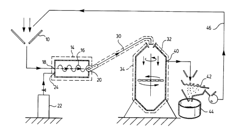
With reference to Figure 1, the apparatus includes a conical inlet 10 into
which the
chips of scrap rubber are fed. 'The chips are conveyed to an insulated cooling
chamber 14. The
chamber is sealed from the atmosphere and has an auger or conveyor belt 16
which transfers
the chips from the point of entry 18 to an exit 20. Liquid nitrogen at a
temperature of about
-180 degrees C. is fed from a cylinder 22 into the chamber at 24.
The chips are in contact with liquid and nitrogen vapour in the chamber and
are
cooled by it. The temperature at the core of the chips which exit the chamber
should be the
range of about -90 to about -110 degrees C. In this range, the rubber becomes
quite brittle and
can be fractured relatively easily in a conventional pulverizer or a milling
machine. At higher
2
CA 02383441 2002-04-24
temperatures, the rubber will not readily fracture when ground. Instead the
rubber will
overheat and jam or gum-up the grinding or pulverizing machine.
At temperatures lower than about minus 110 degrees C., the rubber is not much
more
brittle or easy to comminute than at a temperature within the range of - 90 to
- 110 degrees
C. It becomes increasingly costly and time consuming to cool rubber below -110
degrees C.
and there is no advantage to doing so.
The temperature of the chips can be lowered by increasing the flow of the
nitrogen
into chamber 14. The temperature can also be lowered by slowing the rate of
travel of the
chips through the chamber so that they are in contact with the nitrogen for a
longer period of
time. If the chips are moved by an auger, its rate of rotation can be slowed
or if the chips are
moved by a belt, the belt can be slowed down. To raise the temperature of the
chips, the flow
of nitrogen into chamber 14 can be decreased and the rate of travel of the
chips through the
chamber can be increased.
Cooled chips from the cooling chamber are conveyed pneumatically through an
insulated conduit or tube 30 of relatively small inside diameter. Air from
outside the chamber
mixed with nitrogen vapour exhausted from the chamber is used to propel the
frozen chips
to a comminuting chamber 32. 'The chips remain at about the wane temperature
as they travel
through the tube. The nitrogen vapour and outside air serve not only to keep
the chips cool
before and during comminution but also, as indicated above, serve to propel
the cooled chips
through the tube to comminuting chamber 32.
In chamber 32, the frozen chips fall into the centre of the chamber and are
thrust
violently radially outward against the wall of the chamber by means of one or
more chains.
The chips contact the wall with such force that they shatter into smaller
particles. The outer
3
CA 02383441 2002-04-24
wall of the chamber is insulated at 34 by convention means such as fibreglass
bats or
insulated boards in order to ensure that the temperature of the chips within
the comminuting
chamber is not significantly affected by ambient conditions outside the
chamber. Preferably
the exterior of the chamber is insulated to a minimum of R15 (0.07 BTU/
F/sq.ft.) in order
to minimize heat transfer into the chamber from the air surrounding the
chamber.
The comminuting chamber suitable for use is described in U.S. patents no.
5,839,671
and 6,024,307 issued on November 24, 1998 and February 15, 2000, respectively,
both to
Sand et al. and the contents of these patents are incorporated into this
application by
reference. However, the comminuting chambers described in these patents are
not insulated
and are to be distinguished from comminuting chamber 32 in this respect.
Otherwise the
chambers are similar.
While the chips in the comminuting chamber will be about -90 degrees to about -
110
degrees C., the average temperature of the air within the chamber should not
be lower than
about -60 degrees C. If the temperature is much lower than this, the chains
may become brittle
and break and the walls of the chamber likewise may become brittle and crack.
The
temperature can be adjusted by adjustment of the amount of air which is used
to propel the
chips through tube 30 and the rate at which the mixture of air and nitrogen
vapour is
exhausted from the chamber.
The particles of rubber which exit from the comminuting chamber at 40 are
substantially in the range of 20 to 100 mesh ASTM. If some particles are
larger, they can be
separated from smaller particles by means of a screen 42. Particles which pass
through the
screen are collected in bin 44 and are further treated for separation of
impurities such as
reinforcing steel, fibres and so on. Particles which collect on the screen are
recycled either
4
CA 02383441 2002-04-24
hydraulically or pneumatically through conduit 46 to the inlet 10.
With reference to Figure 2, the apparatus is the same as in Figure 1 except
that an
insulated cooling tank SO in which the rubber chips are tumbled is substituted
for cooling
chamber 14 of Figure 1. In addition, the coolant is a mixture of nitrogen and
alcohol. This is
to be contrasted with the apparatus of Figure 1 where the coolant is pure
nitrogen.
Cooling tank 50 has a number of radially oriented vanes 52 which are mounted
to the
inside wall of a rotating cylinder 54. The chips are introduced into one end
of the cylinder and
are kept in motion or are tumbled by the vanes as the chips travel toward the
other end of the
cylinder.
Blended alcohol from one or more containers 58 flows into the cooling tank and
nitrogen vapour from cylinder 56 is bubbled into the blend. The nitrogen
serves to cool the
mixture to a temperature of about -100 degrees C. The chips mix the alcohol
and nitrogen as
they tumble in the tank. The mixture is partly vapour and partly liquid. The
liquid component
settles in the bottom of the tank at 58 and the chips are continuously
immersed in the mixture
as they tumble within the tank.
A mixture of alcohol and liquid nitrogen is a desirable coolant for a number
of
reasons: first, the mixture is significantly cheaper than pure nitrogen and
the rubber chips can
be cooled at significantly lower cost. Secondly the mixture readily penetrates
into the
interstices of the rubber chips and causes more rapid cooling than nitrogen
vapour which
tends to coat or blanket the surface of the rubber chips but does not engulf
them as the alcohol
blend does. Thirdly, the mixture lubricates the chips and makes them slippery.
Being slippery,
they travel more smoothly in the auger or on the conveyor belt .
A fourth reason why a mixture of alcohol and nitrogen is desirable as a
coolant is that
CA 02383441 2002-04-24
alcohol in the mixture wets the surface of the rubber chips and causes the
rubber fines to
adhere to the larger particles and not to become airborne as dust. Finally,
alcohol tends to act
both as an insulator and a refrigerant. As a result, the rubber chips remain
at the desired
temperature range for longer when coated with alcohol than when un-coated.
This is because
the alcohol, when it coats the rubber chips, temporarily insulates them and,
when the chips
are out of the alcohol blend and airborne in tube 30, freezing continues
through evaporative
cooling.
The alcohol must have a freezing point of below about -120 degrees C. to avoid
freezing in the cooling tank. The alcohol is preferably a blend of two or more
alcohols such
methanol and n-butyl alcohol. A denatured corn alcohol sold under the trade-
mark "Van-Col
729" by Van Waters & Rogers Ltd., a subsidiary of Univar of Weston, Ontario,
Canada is a
suitable n-butyl alcohol. The alcohol may also be a blend of Van-Col and
pentane. Van-Col
is cheaper than either methanol or pentane but its freezing point is -110
degrees C. That
freezing point is within in the acceptable range of temperature for the rubber
chips and should
the chips be at that temperature or lower, the Van-Col will suddenly freeze
and the cooling
chamber will become inoperative. Methanol or pentane, while more expensive,
have lower
freezing points and act to lower the freezing point when blended with Van-Col.
Preferably
sufficient methanol or pentane is added to the Van-Col to ensure that the
freezing point of the
resulting mixture is about -120 degrees C.
Most alcohols in the atmosphere at temperatures above 0 degrees C. are
volatile and
highly combustible, some explosively so. Their vapours are likewise highly
combustible. If
liquid and gaseous alcohol are not insulated from oxygen, they may be ignited
by a spark and
cause serious damage to the equipment containing the rubber chips. They may
also cause
6
CA 02383441 2002-04-24
injury or even death to an operator in the vicinity of the equipment. Nitrogen
in the mixture
creates a gaseous blanket surrounding the chips in the cooling tank and is
effective in
preventing the alcohol and its vapour from igniting should the ambient
temperature exceed
about 0 degrees C. Also effective is the control of the temperature of gases
such as air within
the chamber. As long as the liquid or gaseous alcohol is below about -5
degrees, it is
relatively stable and non-combustible and is suitable for use.
Alcohol cooled by nitrogen is suitable for cooling the rubber chips. Other
means for
cooling the chips are also suitable. A conventional cascade refrigerating
system (not
illustrated) is suitable for this purpose. In such a system two or more
refrigerating systems
using special refrigerants are interconnected and operate simultaneously.
During cooling, the chips should be cooled until the temperature at their
cores is
preferably within the range of -90 to -110 degrees C. The temperature at their
surfaces may
be lower than this without significant impairment in the effectiveness of the
process.
Excess nitrogen in the cooling tank may be expelled to the atmosphere but
preferably
is captured and recycled to the cooling tank or is mixed with outside air and
is used to propel
the chips to comminuting chamber 59. The nitrogen also serves to cool the
comminuting
chamber.
With reference to Figure 3, the apparatus is the same as in Figure 2 except
that
nitrogen and alcohol from cylinder 60 and container 62 flow into a so-called
"tube-in-shell"
or "tube-in-tube" heat exchanger 66. This is to be contrasted with the
apparatus of Figure 2
in which the nitrogen and alcohol flow directly as a mixture into the cooling
tank.
The heat exchanger is conventional and is insulated by an insulating jacket
66. The
exchanger is provided with a coil or "tube" 70 through which the alcohol
flows. The alcohol
7
CA 02383441 2002-04-24
is the same blend as in Figure 2. The nitrogen flows into the hollow interior
or "shell" 72 of
the chamber surrounding the coil.
The alcohol flows through the coil where it is cooled by the nitrogen to a
temperature
within the required range of -90 to -110 degrees C. The cooled alcohol then
flows into cooling
tank 74 where it cools the rubber chips. Nitrogen vapour in the exchanger
flows through
conduit 76 into the cooling tank and from there it flows through tube 78 to
comminuting
chamber 80. The vapour serves to maintain the rubber chips at the required
temperature while
they travel to and into comminuting chamber 80.
The apparatus of Figure 3 consumes less nitrogen to cool the rubber chips than
the
apparatus of Figure 2 and even more so, the apparatus of Figure 1. The cost of
liquid nitrogen
is significantly higher than the cost of the alcohol and for this reason the
apparatus of Figure
3 can be operated at significantly lower cost than the apparatus of Figure 2.
As for the
apparatus of Figure 1, since its coolant is solely nitrogen, it is
considerably more expensive
to operate than the apparatus of the other two Figures.
While the comminuting chamber described above is the preferred apparatus for
comminuting the rubber chips, the chips can be comminuted in other apparatus
such as a
conventional pulverizer or a milling machine.
It will be understood of course that modifications can be made in the
processes
described herein without departing from the scope and purview of the invention
as claimed
in the claims which follow.
8