Note: Descriptions are shown in the official language in which they were submitted.
CA 02383581 2002-02-27
WO 01/17458 PCT/EP00/08712
STENT DELIVERY SYSTEM
BACKGROUND OF THE INVENTION
1) Field of the Invention
In the context of this specification, a stent is a support structure, more or
less
tubular, for placement within a bodily lumen to support the tissue walls of
the
lumen. These stents usually require a delivery system to bring them to
precisely the
desired position within the body of the patient. This invention relates to
stent
delivery, systems.
Two broad categories of stent can be identified. In one category, the stent is
fitted
around a sausage-shaped balloon, the balloon itself being on the distal end of
a
catheter. The catheter is advanced, for example, in the arterial system of the
patient
to the location where the stent is to be placed, and the balloon is then
inflated to
deform the stent plastically, expanding the stent radially against the wall of
the
bodily lumen. Since the deformation is plastic, the stent remains in its
expanded
disposition after deflation of the balloon, and the catheter and balloon
system can
then be withdrawn.
A second category of stent comprises stents which are self-expanding. For
these
stents, the delivery system employs some sort of sheath to constrain the stent
in a
radially small configuration. When the stent is in the desired location, the
constraint
radially outside the stent is withdrawn, allowing the stent to "spring"
radially
outwardly to press against the tissue wall of the lumen and permit withdrawal
of the
delivery system.
CA 02383581 2002-02-27
WO 01/17458 PCT/EP00/08712
2
The present invention relates to a delivery system for a self-expanding stent.
In this
specification, the expression "proximal" relates to a point at the end of the
delivery
system held by the physician, and "distal" to the opposite end.
2. Description of the Related Art
US-A-5,645,559 (Hachtman et al.) discloses a delivery system for a radially
self-
expanding stent, the system having an inner tube around which the stent is
fitted,
and an outer tube that radially compresses the stent. Figures 5 to 8 of the
drawings
of US'559 shows progressive proximal withdrawal of the outer tube so as to
release
the self-expanding stent progressively along its length commencing with the
distal
end, and with the extreme proximal end of the stent being the last part of the
stent to
be released radially outwardly.
US'559 mentions the problem that during this release process there have been
instances of axial travel of the stent relative to the delivery system, and
not under
the control of the surgeon or radiologist, so that the stent can end up in a
position in
the bodily lumen either proximal of or distal of, the desired location in the
lumen.
US'559 addresses this problem and proposes as a solution the addition of a
relatively soft sleeve element which sits between the stent and the inner
tube. This
soft sleeve is required to exhibit on its radially outward surface a plurality
of
circumferential ribs. US'559 stresses that the ribs should be adjacent to the
medial
portion of the stent. Its Figure 22 shows a bed 21 for the stent and what
appear to
be 14 ribs all in the central part of the length of the bed.
EP-A-775 470 discloses a stent delivery system with components added to
provide
a scratch protection capacity. One of these components can be a ring on the
luminal
surface at the distal end of sheath which surrounds the stent and is withdrawn
proximally ro release the stent. The inside diameter of the ring is shown to
be the
same as the inside diameter of the sheath proximal of the ring.
CA 02383581 2002-02-27
WO 01/17458 PCT/EP00/08712
3
SUMMARY OF THE INVENTION
The present invention also addresses the problem of uncontrolled movement of a
self-expanding stent relative to a stent delivery system, during the process
of
deploying the stent. The features which characterise the present invention are
recited in claim 1 below. The dependent claims recite optional or preferred
features.
The technical features of the present invention deliver an improved technical
effect.
The degree to which a self-expanding stent is gripped by a stent delivery
system
involves a judicious balance between different factors, and the present
invention
offers the possibility of a better balance, as follows.
Unwanted jumping of the stent out of the delivery system can be combated by
providing a tight fit between the constraining surfaces inside and outside the
stent.
In other words, one can confine the stent in a very tight annular space,
giving the
stent minimal opportunity to spring out of the annular space prematurely.
However,
it is also important to ensure that, when release of the stent is desired,
release can
proceed smoothly. For this purpose, one would choose to have easy axial
sliding
between the constraining surfaces inside and outside the stent cylinder. In
other
words, it must be possible easily to proximally withdraw the outer
constraining
sheath. This factor points towards a loose fit of the sheath on the stent.
One insight which the present inventor has brought to this complex is the
realisation
that the grip of the delivery system on the stent gets weaker as the sheath
progressively withdraws since the area of sheath overlying the compressed part
of
the length of the stent is progressively shrinking. Thus, the likelihood of an
uncontrolled spring of the stent away from the delivery system goes up in
proportion to the amount of proximal withdrawal of the sheath. Thus, as long
as the
CA 02383581 2002-02-27
WO 01/17458 PCT/EP00/08712
4
sheath grips tightly the proximal end of the stent in the last stages of stent
release a
looser grip on the distal end of the stent, in the early stages of release, is
likely to be
tolerable. If one assumes that resistance to proximal withdrawal of the sheath
will
be in proportion to the surface area of the sheath in sliding contact with the
radially
outside surface of the stent, then one can appreciate that the force required
to pull
the sheath proximally will tend to ease downwards, as the sheath progressively
withdraws from the stent surface.
According to the present invention, pinch zones interact in the last stages of
sheath
withdrawal. This raises frictional resistance, but from a low level. The
pinching
effect enhances gripping of the stent when enhanced gripping is needed,
however
not before then.
With the invention, it will be noted, there is no interaction of the pinch
zone on the
sheath and the pinch zone on the catheter until after a majority of the length
of the
stent has already been released. Thus, the pinch zones do not materially add
to the
sliding resistance during release of the stent, until the last part of the
release
process. During this last part of the release process, the amount of sliding
resistance
is less than the frictional resistance at the start of the release process so
that there is
some scope for a tighter squeezing of the proximal end of the stent between
two
annular surfaces, without taking the frictional resistance back up to an
unacceptably
high level. Indeed, a judicious balance of materials and dimensions should
enable a
profiling of the frictional resistance so that the interaction between the
first and
second pinch zones compensates for the decline of frictional resistance with
proximal movement of the sleeve, possibly leading to a more or less steady
level of
force needed for withdrawal of the sheath over the full length of the stent.
Alternatively, the profile could be arranged to provide a signal, in terms of
a
characteristic tensile stress profile, delivered to the surgeon/radiologist
that the
second pinch zone has passed over the first pinch zone.
CA 02383581 2002-02-27
WO 01/17458 PCT/EP00/08712
It is conventional in stent delivery systems to equip the delivery system with
radioactive markers to enable radiologists to track the location of the distal
end of
the system. Often, the catheter is fitted with distal and proximal markers, of
known
disposition relative to the stent bed, and the constraining sheath also has a
marker so
that the degree of withdrawal of the sheath, relative to the stent bed, can
also be
tracked. Conveniently, these radioactive markers are thin metal bands crimped
or
swaged onto the outside surface of a polymeric tubular element. In one
preferred
embodiment of the present invention, such a metal radioactive marker band is
fitted
around the sheath at its distal end, and squeezed into the outside wall of the
sheath
by an amount calculated to displace the sheath wall, inside the marker band
just
enough to create the second pinch zone.
One convenient way to create the first pinch zone is by depositing on the
cylindrical
wall of a tube of the catheter an annulus of cured polymeric adhesive.
Preferably, a
metal radioactive marker band can be set within the same adhesive deposit,
thereby
to form the proximal end of the stent bed.
BRIEF DESCRIPTION OF THE DRAWINGS
For a better understanding of the present invention, and to show more clearly
how
the same may be carried into effect, reference will now be made, by way of
example, to the accompanying drawings, in which:
Figure 1 is a longitudinal diametric section through the distal tip region of
a
delivery system for a self-expanding stent, showing the stent prior to
release; and
Figure 2 is a section similar to that of Figure 1, showing the stent partially
released.
CA 02383581 2002-02-27
WO 01/17458 PCT/EP00/08712
6
DETAILED DESCRIPTION OF THE PREFERRED EMBODIMENT
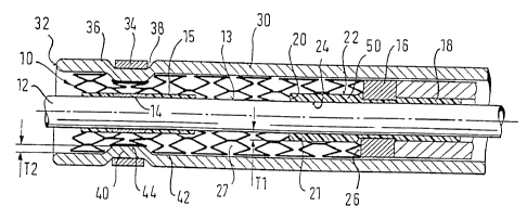
Figure 1 shows a delivery system for a stent 10. The system is based on a
tubular
catheter tube 12, designed to be advanced along a guidewire (not shown). The
catheter tube carries on its cylindrical surface 13 a distal marker 14,
retained axially
in position on the tube 12 by a short length of polymeric material 15 melted
onto the
tube 12. A proximal marker band 16 is retained on the tube 12 in a cured
annular
bed 18 of polymeric adhesive. This adhesive bed extends distally of the marker
band 16 as far as a distal end 20 to form a short cylindrical length 21 of the
cured
adhesive, distal in relation to the marker band 16, with a radially outwardly
facing
surface 22 and a radially inwardly facing surface 24 bonded to the cylindrical
surface of the tube 12. This cylindrical zone, radially between cylindrical
surfaces
22 and 24, has a radial thickness Tl. Reference is made to the fact that the
marker
band 16 provides a distal-facing end surface 26 which defines the proximal end
of a
bed 27 to receive the stent 10.
Overlying the stent 10 is an outer catheter tube 30 which extends to a distal
tip 32
beyond the distal end of the stent 10. Close to the distal tip 32 is a further
radioactive metal marker band 34 which is swaged into the outside wall surface
36
of the outer tube 30, causing elastic deformation of the outer tube 30,
locally
radially inside the band 34, so that the marker band 34 sits in a ring recess
38 in the
outer wall of the tube 30. This ring recess 38 has its counterpart a ring
which forms
a pinch zone 40 which protrudes inwardly of the inside wall 42 of the outer
tube 30
by the band 34, and locally radially inside the marker band 34. This radially
inwardly protruding pinch zone has a radially inside surface 44, and the
radially
inward extent of the pinch zone 40 between surfaces 42 and 44 is T2. It will
be
seen that stent 10 fits snugly around the inside surfaces 42 and 44 of the
outer tube
30. One must remember that a self-expanding stent at body temperature is
seeking
to expand radially and so will naturally follow closely the contours of any
CA 02383581 2002-02-27
WO 01/17458 PCTIEPOO/08712
7
constraining outer tube (just as it will ultimately follow closely the
contours of the
bodily lumen in which it is deployed).
Turning now to Figure 2, in which like elements are given the same reference
numerals, one sees that the outer tube 30 has been withdrawn relative to the
inner
tube 12, sufficiently far to release most of the length of the stent 10, and
to a point
in which the first pinch zone 50 provided by the polymer between cylindrical
surfaces 22 and 24 directly faces the second pinch zone 40 inside the marker
band
34. It is to be noted that nowhere is the thickness of the stent 10 less than
its
relaxed thickness. The stents used by applicant are made of Nitinol memory
metal
and so, in the context of the present invention, substantially incompressible.
It must
be noted, however, that there is spacing shown in Figure 1, between the stent
and
the surfaces radially inside it, corresponding to the reality that the stent
has
expanded as much as it is permitted to expand, at all times. Note further that
in
Figure 2 there appears to be no gap between the stent 10 and the first pinch
zone 50,
but only in the part of the length of the stent which lies radially directly
inside the
second pinch zone 40. Proximally of pinch zone 40 at the very distal end of
the
stent 10, there is still a spacing between the stent 10 and the first pinch
zone 50.
However, with a further withdrawal movement of the outer tube 30, bringing the
second pinch zone 40 to the proximal end of the first pinch zone 50, this gap
will
disappear.
Continued proximal withdrawal of the outer tube 32 will carry the pinch zone
40
proximally beyond pinch zone 50, at which point the stent 10 will be able to
ease
out of the proximal end of its bed. By that point, such a large proportion of
the
length of the stent will have taken up position on the bodily lumen wall that
any out
of control springing or jumping of the stent, and uncontrolled axial movement
of the
stent relative to the bed, will be either eliminated altogether or reduced to
an
acceptably minuscule level.
CA 02383581 2002-02-27
WO 01/17458 PCTIEPOO/08712
8
As with conventional delivery systems, withdrawal of the outer sheath past the
proximal end of the stent deploys the self-expanding stent fully, and allows
the
delivery system to be retracted from the patient's body.
What is shown in the drawings represents what for the applicant at the present
time
is the best mode of putting the invention into effect. However, readers will
appreciate that a wealth of variations is possible for those skilled in the
art.
Those skilled in the art will be familiar with the materials with which self-
expanding stents are constructed, and with the materials with which delivery
systems for such stents are constructed. Those skilled in the art are familiar
with
assembly techniques for achieving the required degrees of flexibility,
pushability,
column strength and torquability in stent delivery systems.
As mentioned above, there is scope for profiling the first and second pinch
zones,
other than as shown in the drawings, in order to achieve the desired profiles
of
withdrawal force, and further refine the degree of control over the release of
self-
expanding stents from such delivery systems. There is also, naturally, much
scope
for refining the design and provision of marker bands, and for co-ordinating
the
distribution of marker bands and pinch zones to achieve synergistic effects.