Note: Descriptions are shown in the official language in which they were submitted.
WO 01/18948 CA 02383883 2002-03-05 PCT/US00/24471
APPARATUS AND METHOD FOR PROPULSION
of which the following is a specification:
BACKGROUND OF THE INVENTION
1. Field of the Invention:
This invention relates to methods and apparatus for
providing propulsion, in particular methods and apparatus
for providing propulsion using a scattered electron beam.
2. Description of the Related Art
The attractive gravitational force has been the subject
of investigation for centuries. Traditionally, gravitational
attraction has been investigated in the field of astrophysics
applying a large scale perspective of cosmological spacetime,
as distinguished from currently held theories of atomic and
subatomic structure. However, gravity originates on the
2 0 atomic scale. In Newtonian gravitation, the mutual attraction
between two particles of masses zn, and nz~ separated by a
distance r is
F=Gm,zn2 (23.1)
r
where G is the gravitational constant, its value being
2 5 6.67 X 10-" Nm2kg-'. Although Newton's theory gives a correct
quantitative description of the gravitational force, the most
elementary feature of gravitation is still not well defined.
What is the most important feature of gravitation in terms of
fundamental principles? By comparing Newton's second law,
30 F=nza (23.2)
with his law of gravitation, we can describe the motion of a
freely falling object by using the following equation:
m; a = mh G~~ r ( 2 3 . 3 )
r
where m, and nz,~ represent respectively the object's inertial
3 5 mass (inversely proportional to acceleration) and the
WO 01/18948 CA 02383883 2002-03-05 PCT/US00/24471
2
gravitational mass (directly proportional to gravitational
force), M~ is the gravitational mass of the Earth, and r is the
position vector of the object taken from the center of the
Earth. The above equation can be rewritten as
a- m'~ CGM~~ (23.4)
m. r2
Extensive experimentation dating from Galileo's Pisa
experiment to the present has shown that irrespective of the
object chosen, the acceleration of an object produced by the
gravitational force is the same, which from Eq. (23.4) implies
1 0 that the value of nz~ l m; should be the same for all objects. In
other words, we have
m~ = universal constant ( 2 3 . 5 )
rn;
the equivalence of the gravitational mass and the inertial
mass- the fractional deviation of Eq. (23.5) from a constant is
1 5 experimentally confirmed to less 1 X 10-" [1]. In physics, the
discovery of a universal constant often leads to the
development of an entirely new theory. From the universal
constancy of the velocity of light c, the special theory of
relativity was derived; and from Planck's constant h, the
2 0 quantum theory was deduced. Therefore, the universal
constant mR l m; should be the key to the gravitational
problem. The theoretical difficulty with Newtonian
gravitation is to explain just why relation, Eq. (23.5), exists
implicitly in Newton's theory as a separate law of nature
2 5 besides Eqs. (23.1 ) and (23.2). Furthermore, discrepancies
between certain astronomical observations and predictions
based on Newtonian celestial mechanics exist, and they
apparently could not be reconciled until the development of
Einstein's theory of general relativity which can be
3 0 transformed to Newtonian gravitation on the scale in which
Newton's theory holds.
Einstein's general relativity is the geometric theory of
gravitation developed by Albert Einstein, whereby he
intended to incorporate and extend the special theory of
3 5 relativity to accelerated frames of reference. Einstein's
WO 01/18948 CA 02383883 2002-03-05 PCT/US00/24471
3
theory of general relativity is based on a flawed dynamic
formulation of Galileo's law. Einstein took as the basis to
postulate his gravitational field equations a certain
kinematical consequence of a law which he called the
"Principle of Equivalence" which states that it is impossible to
distinguish a uniform gravitational field from an accelerated
frame. However, the two are not equivalent since they
obviously depend on the direction of acceleration relative to
the gravitation body and the distance from the gravitating
body since the gravitational force is a central force. (In the
latter case, only a line of a massive body may be exactly
radial, not the entire mass.) And, this assumption leads to
conflicts with special relativity. The success of Einstein's
gravity equation can be traced to a successful solution which
arises from assumptions and approximations whereby the
form of the solution ultimately conflicts with the properties
of the original equation, no solution is consistent with the
experimental data in the case of the possible cosmological
solutions of Einstein's general relativity. All cosmological
2 0 solutions of general relativity predict a decelerating universe
from a postulated initial condition of a "Big Bang" expansion
[2]. The astrophysical data reveals an accelerating cosmos [3]
which invalidates Einstein's equation. It has been shown that
the correct basis of gravitation is not according to Einstein's
2 5 equation; instead the origin of gravity is the relativistic
correction of spacetime itself which is analogous to the special
relativistic corrections of inertial parameters-- increase in
mass, dilation in time, and contraction in length in the
direction of constant relative motion of separate inertial
3 0 frames. On this basis, the observed acceleration of the
cosmos is predict as given in the Cosmology Section of Mills
[4]. Furthermore, Einstein's general relativity is a partial
theory in that it deals with matter on a cosmological scale,
but not an atomic scale. All gravitating bodies are composed
3 5 of matter and are collections of atoms which are composed of
fundamental particles such as electrons, which are leptons,
and quarks which make up protons and neutrons. Gravity
WO 01/18948 CA 02383883 2002-03-05 PCT/US00/24471
4
originates from the fundamental particles.
As a result of the erroneous assumptions and
incomplete or erroneous models and theories, the
development of useful or functional systems and structures
requiring an accurate understanding of atomic structure and
the nature of gravity on the atomic scale have been inhibited.
On a scale of gravitating bodies, the Theory of General
Relativity is correct experimentally; however, it is
incompatible with observation of an acceleration expansion
on a cosmological scale, and is incompatible with the current
atomic theory of quantum mechanics. And, the Schrodinger
equation upon which quantum mechanics is based does not
explain the phenomenon of gravity and, in fact, predicts
infinite gravitational fields in empty vacuum. Thus, advances
in development of propulsion systems which function
according to gravitational forces on the atomic scale are
prohibited.
SUMMARY OF THE INVENTION
2 0 Overview of the Novel Theoretical Basis
While the inventive methods and apparatus described in
detail further below may be practiced as described, the
following discussion of a novel theoretical basis of the
invention is provided for additional understanding.
2 5 A novel atomic theory is disclosed in R. Mills, The Grand
Unified Theory of Classical Quantum Mechanics, January
2000 Edition, BIackLight Power, Inc., Cranbury, New Jersey,
Distributed by Amazon.com which are incorporated herein by
this reference. The Schwarzschild metric gives the
3 0 relationship whereby matter causes relativistic corrections to
spacetime that determines the curvature of spacetime and is
the origin of gravity. The correction is based on the
boundary conditions that no signal can travel faster that the
speed of light including the gravitational field that propagates
3 5 following particle production from a photon wherein the
particle has a finite gravitational velocity given by Newton's
Law of Gravitation. It is possible to give the electron a spatial
WO 01/18948 CA 02383883 2002-03-05 PCT/US00/24471
velocity function having negative curvature and, therefore,
cause the electron to have a positive inertial mass but a
negative gravitational mass. An engineered spacecraft is
disclosed.
5 Propulsion Methods and Means
The present invention of a propulsion device comprises
a source of matter, a means to give the matter a spatial
velocity function having negative curvature which causes the
matter to react to a gravitation body such that it has a
negative gravitational mass, and a means to produce a force
on the matter in opposition to the repulsive gravitational
force between the matter and the gravitating body. The force
on the matter is applied in the opposite direction of the force
of the gravitating body on the matter. This second force is
1 5 provided by one or more of an electric field, a magnetic field
or an electromagnetic field. The repulsive force of the
gravitating body is then transferred to the source of the
second force which further transfers the force to an attached
structure to be propelled. In response to the applied force,
2 0 the matter produces useful work against the gravitational
field of the gravitating body.
In one embodiment the propulsion means comprises a
means to inject particles such as electrons which serve as the
matter. It is possible to elastically scatter electrons of an
2 5 electron beam from atoms such that electrons having a
spatial velocity function having negative curvature
(hyperbolic electrons) emerge. The emerging beam of
hyperbolic electrons experience a force away from a
gravitating body (e.g. the Earth) and the beam will tend to
3 0 move upward (away from the Earth). To use this invention
for propulsion, the upward force of the electron beam is
transferred to a negatively charged plate. The Coulombic
repulsion between the beam of electrons and the negatively
charged plate causes the plate (and anything connected to the
3 5 plate) to lift.
WO 01/18948 CA 02383883 2002-03-05 PCT/US00/24471
6
BRIEF DESCRIPTION OF THE FIGURES
These and further features of the present invention will be
better understood by reading the following Detailed
Description of the Invention taken together with the Drawing,
wherein:
FIGURE 1 is a saddle;
FIGURE 2 is a pseudosphere;
FIGURE 3 is a propulsion device according to the
present invention;
FIGURE 4 is the magnitude of the velocity distribution
( v~ ) on a two dimension sphere along the z-axis (vertical
axis) of a hyperbolic electron;
FIGURE 5 is a cutaway of the magnitude of the velocity
distribution ( v~ ) on a two dimension sphere along the z-axis
(vertical axis) of a hyperbolic electron;
FIGURE 6 is an propulsion device driven by hyperbolic
electrons;
FIGURE 7 is a drawing of an propulsion apparatus
according to one embodiment of the present invention to give
2 0 electrons a spatial velocity function having negative
curvature and, therefore, cause the electrons to have a
negative gravitational mass;
FIGURE 8 is a schematic of the hyperbolic path of a
hyperbolic electron of mass m in an inverse-square repulsive
2 5 field of a gravitating body comprised of matter of positive
curvature of the velocity surface of total mass M;
FIGURE 9 is a schematic of the helical motion of a
hyperbolic electron in a synchrotron orbit in the xy-plane
with a repulsive gravitational force along the +z axis which is
3 0 transferred to the capacitor, and
FIGURE 10 is a schematic of the forces on a spinning
craft which is caused to tilt.
DETAILED DESCRIPTION OF THE INVENTION
3 5 The theoretical background of the present invention is
given the book by Mills [4] which is herein incorporated by
WO 01/18948 CA 02383883 2002-03-05 PCT/US00/24471
7
reference. The equations numbers given below refer to the
corresponding equations of Mills book.
The provision of the equivalence of inertial and
gravitational mass by the Mills theory of fundamental
particles wherein spacetime is Riemannian due to its
relativistic correction with particle production permits the
correct derivation of the General Theory. In the case of
ordinary matter (an example of an extraordinary state of
matter called a hyperbolic electron is given infra), the nature
of chemical bonding is electric and magnetic, and the angular
momentum of each bound electron is always ~r independent
of material such as wood or metal. The angular momentum
with a central field is given by Eq. ( 1.57). In this case, each
infinitesimal point of the electron orbitsphere (given in Chp. 1
of Mills book as a solution of the electron wavefunction with
a nonradiative boundary constraint) of mass m; is the inertial
mass according to the inertial angular momentum. It also is
the gravitational mass according to the gravitational angular
momentum. The inertial and gravitational mass of electrons
2 0 and nucleons in ordinary matter are equivalent.
The provision of the two-dimensional nature of matter
permits the unification of atomic, subatomic, and cosmological
gravitation. The unified theory of gravitation is derived by
first establishing a metric. A space in which the curvature
2 5 tensor has the following form:
R v. a/3 - K'~gvag~p -gNagvp) (26.1 )
is called a space of constant curvature; it is a four-
dimensional generalization of Friedmann-Lobachevsky space.
The constant K is called the constant of curvature. Th a
3 0 curvature of spacetime results from a discontinuity of matter
having curvature confined to two spatial dimensions. This is
the property of all matter as an orbitsphere. Consider an
isolated orbitsphere and radial distances, r, from its center.
For r- less than r" there is no mass; thus, spacetime is flat or
3 5 Euclidean. The curvature tensor applies to all space of the
inertial frame considered: thus, for r less than r", K = 0. At
r = r" there exists a discontinuity of mass of the orbitsphere.
WO 01/18948 CA 02383883 2002-03-05 PCT/US00/24471
8
This results in a discontinuity of the curvature tensor for
radial distances greater than or equal to rn. The discontinuity
requires relativistic corrections to spacetime itself. It
requires radial length contraction and time dilation that
results in the curvature of spacetime. The gravitational
radius of the orbitsphere and infinitesimal temporal
displacement in spacetime which is curved by the presence of
the orbitsphere are derived in the Gravity Section of Mills [4].
The Schwarzschild metric gives the relationship
whereby matter causes relativistic corrections to spacetime
that determines the curvature of spacetime and is the origin
of gravity. The correction is based on the boundary
conditions that no signal can travel faster that the speed of
light including the gravitational field that propagates
following particle production from a photon wherein the
particle has a finite gravitational velocity given by Newton's
Law of Gravitation. The separation of proper time between
two events x"' and x"' +dx"' given by Eq. (23.38), the
Schwarzschild metric [5-6], is
dr2=Cl_2Gmoldt=- 2 CI-2Gmol drz+r2d92+r'sinz6d~2 (26.2)
c'r J c c Jr
Eq. (26.2) can be reduced to Newton's Law of Gravitation for
the gravitational radius of the particle, much less than ra,
the radius of the particle at production ( r* « 1), where the
Ya
radius of the particle is its Compton wavelength bar ( ra = ~,~).
2 5 F, = Gm2m' ( 2 6 . 3 )
r
where G is the Newtonian gravitational constant. Eq. (26.2)
relativistically corrects Newton's gravitational theory. In an
analogous manner, Lorentz transformations correct Newton's
laws of mechanics.
3 0 The effects of gravity preclude the existence of inertial
frames in a large region, and only local inertial frames,
between which relationships are determined by gravity are
possible. In short, the effects of gravity are only in the
determination of the local inertial frames. The frames
WO 01/18948 CA 02383883 2002-03-05 PCT/US00/24471
9
depend on gravity, and the frames describe the spacetime
background of the motion of matter. Therefore, differing
from other kinds of forces, gravity which influences the
motion of matter by determining the properties of spacetime
is itself described by the metric of spacetime. It was
demonstrated in the Gravity Section of Mills [4] that gravity
arises from the two spatial dimensional mass density
functions of the fundamental particles.
It is demonstrated in the One Electron Atom Section of
1 0 Mills [4] that a bound electron given as a solution of the
electron wavefunction with a nonradiative boundary
constraint is a two-dimensional spherical shell- an
orbitsphere. On the atomic scale, the curvature, K, is given
by 1 , where rn is the radius of the radial delta function of
Yn
the orbitsphere. The velocity of the electron is a constant on
this two dimensional sphere. It is this local, positive
curvature of the electron that causes gravity. It is worth
noting that all ordinary matter, comprised of leptons and
quarks, has positive curvature. Euclidean plane geometry
2 0 asserts that (in a plane) the sum of the angles of a triangle
equals 180°. In fact, this is the definition of a flat surface. For
a triangle on an orbitsphere the sum of the angles is greater
than 180°, and the orbitsphere has positive curvature. For
some surfaces the sum of the angles of a triangle is less than
2 5 180°; these are said to have negative curvature.
sum of angles
of a triangle type of surface
> 180° positive curvature
- 180° flat
3 5 < 180° negative curvature
WO 01/18948 CA 02383883 2002-03-05 PCT/US00/24471
I0
The measure of Gaussian curvature, K, at a point on a
two dimensional surface is
K= 1 (26.4)
r, r2
the inverse product of the radius of the maximum and
minimum circles, r, and r2, which fit the surface at the point,
and the radii are normal to the surface at the point. By a
theorem of Euler, these two circles lie in orthogonal planes.
For a sphere, the radii of the two circles of curvature are the
same at every point and equivalent to the radius of a great
circle of the sphere. Thus, the sphere is a surface of constant
curvature;
K= 1 (26.5)
r
at every point. In case of positive curvature of which the
sphere is an example, the circles fall on the same side of the
surface, but when the circles are on opposite sides, the curve
has negative curvature. A saddle, a cantenoid, and a
pseudosphere are negatively curved. The general equation of
a saddle is
(26.6)
2 0 where a and b are constants. The curvature of the surface of
Eq. (26.6) is
_ 2 ~z
K 4azb' a'' + b; + 4 (26.7)
A saddle is shown schematically in FIGURE 1.
A pseudosphere is constructed by revolving the tractrix
2 5 about its asymptote. For the tractrix, the length of any
tangent measured from the point of tangency to the x-axis is
equal to the height R of the curve from its asymptote-in this
case the x-axis. The pseudosphere is a surface of constant
negative curvature. The curvature, K
3 0 K=ll = R1 (26.8)
ri j~_
given by the product of the two principal curvatures on
opposite sides of the surface is equal to the inverse of R
squared at every point where R is the equitangent. R is also
WO 01/18948 CA 02383883 2002-03-05 PCT/US00/24471
11
known as the radius of the pseudosphere. A pseudosphere is
shown schematically in FIGURE 2.
In the case of a sphere, surfaces of constant potential
are concentric spherical shells. The general law of potential
for surfaces of constant curvature is
V - 1 1 - 1 (26.9)
4 n~~, r, rz 4 ~E"R
In the case of a pseudosphere the radii ~-, and r" the two
principal curvatures, represent the distances measured along
the normal from the negative potential surface to the two
sheets of its evolute, envelop of normals (cantenoid and x-
axis). The force is given as the gradient of the potential
which is proportional to Z in the case of a sphere.
r
All matter is comprised of fundamental particles, and
all fundamental particles exists as mass confined to two
spatial dimensions. The particle's velocity surface is
positively curved in the case of an orbitsphere, or the
velocity surface is negatively curved in the case of an
electron as a hyperboloid (hereafter called a hyperbolic
electron given in the Hyperbolic Electrons Section). The effect
2 0 of this "local" curvature on the non-local spacetime is to cause
it to be Riemannian, in the case of an orbitsphere, or
hyperbolic, in the case of a hyperbolic electron, as opposed to
Euclidean which is manifest as a gravitational field that is
attractive or repulsive, respectively. Thus, the spacetime is
2 5 curved with constant spherical curvature in the case of an
orbitsphere, or spacetime is curved with hyperbolic
curvature in the case of a hyperbolic electron.
The relativistic correction for spacetime dilation and
contraction due to the production of a particle with positive
3 0 curvature is given by Eq. (23.17)
1z
f(r)= 1-~v~~ (26.10)
c
The derivation of the relativistic correction factor of
spacetime was based on the constant maximum velocity of
light and a finite positive Newtonian gravitational velocity v,s
WU 01/18948 CA 02383883 2002-03-05 PCT/US00/24471
12
of the particle given by
2Gmo - 2Gmo (26.1 1 )
~c
Consider a Newtonian gravitational radius, r~, of each
orbitsphere of the particle production event, each of mass m
r~ - 2Gm (26.12)
c
where G is the Newtonian gravitational constant.
Substitution of Eq. (26.11 ) or Eq. (26.12) into the
Schwarzschild metric Eq. (26.2), gives
d2'= 1- v'~ 2 dt'- Z 1- vg 2 dr'+r2d9Z+r'sin''9d~2 (26.13)
(c~ c (c
and
d22=C1-rRJdt'- 2IC1-rR, dr'+r2d6Z+r'sin26dc~2~ (26.14)
r c rr
respectively. The solutions for the Schwarzschild metric exist
wherein the relativistic correction to the gravitational
velocity v~ and the gravitational radius r~ are of the opposite
sign (i.e. negative). In these cases the Schwarzschild metric
Eq. (26.2), is
_,
d~'= 1+ v~ Z dtr- 1 1+ v~ 2 dr2+r2d9'+r'sin29d~2 (26.15)
(c) c (c
and
l _,
d22 = C1 + r~ Jdt2 - 1 C1 + rR ~ dr2 + red 92 + r'' sine Bd~2 ( 2 6 .16 )
r c- r
2 0 The metric given by Eqs. (26.13-26.14) corresponds to
positive curvature. The metric given by Eqs. (26.15-26.16)
corresponds to negative curvature. The negative solution
arises naturally as a match to the boundary condition of
matter with a velocity function having negative curvature.
2 5 Consider the case of pair production given in the Gravity
Section of Mills [4]. The photon equation given in the
Equation of the Photon Section of Mills [4] is equivalent to the
electron and positron functions given by in the One Electron
Atom Section of Mills [4]. The velocity of any point on the
3 0 positively curved electron orbitsphere is constant which
W~ 01/18948 CA 02383883 2002-03-05
PCT/US00/24471
13
correspond to the trigonometric function given in Eqs. ( 1.68-
1.69). At particle production, the relativistic corrections to
spacetime due to the constant gravitational velocity v~ are
given by Eqs. (26.13-26.14). In the case of negative
curvature, the electron velocity as a function of position is not
constant. It may be described by a harmonic variation which
corresponds to an imaginary velocity. The trigonometric
function of the positively curved electron orbitsphere given
in Eqs. (1.68-1.69) becomes a hyperbolic function (e.g. cosh)
in the case of a negatively curved electron. Substitution of an
imaginary velocity with respect to a gravitating body into Eq.
(26.13) givens Eq. (26.15). Substitution a negative radius of
curvature with respect to a gravitating body into Eq. (26.14)
gives Eq. (26.16). Thus, force corresponding to a negative
gravitational mass can be created by forcing matter into
negative curvature of the velocity surface. A fundamental
particle with negative curvature of the velocity surface would
experience a central but repulsive force with a gravitating
body comprised of matter of positive curvature of the
2 0 velocity surface.
POSITIVE ZERO AND NEGATIVE GRAVITATIONAL MASS
In the case of Einstein's gravity equation (Eq. (23.40)),
the Einstein's Tensor GNv, is equal to the stress-energy-
2 5 momentum tensor T~,~. The only possibility is for the
gravitational mass to be equivalent to the inertial mass. A
particle of zero or negative gravitational mass is not possible.
However, it is shown in the Gravity Section of Mills [4] that
the correct basis of gravitation is not according to Einstein's
3 0 equation (Eq. (23.40)); instead the origin of gravity is the
relativistic correction of spacetime itself which is analogous to
the special relativistic corrections of inertial parameters--
increase in mass, dilation in time, and contraction in length in
the direction of constant relative motion of separate inertial
3 5 frames. On this basis, the observed acceleration of the
cosmos is predict as given in the Cosmology Section of Mills
[4].
WO 01/18948 CA 02383883 2002-03-05 PCT/US00/24471
14
The Schwarzschild metric gives the relationship
whereby matter causes relativistic corrections to spacetime
that determines the curvature of spacetime and is the origin
of gravity. Matter arises during particle production from a
photon. According to Newton's Law of Gravitation, the
production of a particle of finite mass gives rise to a
gravitational velocity of the particle. The gravitational
velocity determines the energy and the corresponding
eccentricity and trajectory of the gravitational orbit of the
particle. The eccentricity a given by Newton's differential
equations of motion in the case of the central field (Eq.
(23.49-23.50)) permits the classification of the orbits
according to the total energy E as follows [7]:
E<0, a<1 ellipse
E < 0, a = 0 circle (special case of ellipse)
E = 0, a =1 parabolic orbit
E > 0, a > 1 hyperbolic orbit
(26.17)
Since E = T + V and is constant, the closed orbits are those for
2 5 which T <~ V~, and the open orbits are those for which T >-~ V~ . It
can be shown that the time average of the kinetic energy,
< T >, for elliptic motion in an inverse square field is 1 / 2 that
of the time average of the potential energy, < V >.
<T>=1/2<V>.
3 0 In the case that a particle of inertial mass m is
observed to have a speed v~,, a distance from a massive object
f~, and a direction of motion makes that an angle ~ with the
radius vector from the object (including a particle) of mass
M, the total energy is given by
1 , GMm 1 ~ GMm
3 5 E=-mW - --mv« - =constant (26. 18)
2 j~ ? ro
The orbit will be elliptic, parabolic, or hyperbolic. according to
WO X1/18948 CA 02383883 2002-03-05 PCT/US00/24471
1 5
whether E is negative, zero, or positive. Accordingly, if vo is
less than, equal to, or greater than 2GM, the orbit will be an
ro
ellipse, a parabola, or a hyperbola, respectively. Since h, the
angular momentum per unit mass, is
h=L/rn=~rxv~=rovosin~ (26.19)
The eccentricity e, from Eq. (23.63) may be written as
e=[1+ v'-_2GM rovo'sin2~~"Z (26.20)
o ro G_Mz
As shown in the Gravity Section of Mills [4] (Eq.
(23.35)), the production of a particle requires that the
velocity of each of the point masses of the particle is
equivalent to the Newtonian gravitational escape velocity v~
of the superposition of the point masses of the antiparticle.
2Gm 2Gmo (26.21 )
v~ _
~c
From Eq. (26.20) and Eq. (26.17), the eccentricity is one and
the particle production trajectory is a parabola relative to the
center of mass of the antiparticle. The right-hand side of Eq.
(23.43) represents the correction to the laboratory coordinate
metric for time corresponding to the relativistic correction of
spacetime by the particle production event. Riemannian
2 0 space is conservative. Only changes in the metric of
spacetime during particle production must be considered.
The changes must be conservative. For example, pair
production occurs in the presence of a heavy body. A nucleus
which existed before the production event only serves to
2 5 conserve momentum but is not a factor in determining the
change in the properties of spacetime as a consequence of the
pair production event. The effect of this and other external
gravitating bodies are equal on the photon and resulting
particle and antiparticle and do not effect the boundary
3 0 conditions for particle production. For particle production to
occur, the particle must possess the escape velocity relative
to the antiparticle where Eqs. (23.34), (23.48), and (23.140)
apply. In other cases not involving particle production such
as a special electron scattering event wherein hyperbolic
WO 01/18948 CA 02383883 2002-03-05 PCT/US00/24471
1 6
electron production occurs as given infra, the presence of an
external gravitating body must be considered. The curvature
of spacetime due to the presence of a gravitating body and
the constant maximum velocity of the speed of light comprise
boundary conditions for hyperbolic electron production from
a free electron.
With particle production, the form of the outgoing
gravitational field front traveling at the speed of light (Eq.
(23.10)) is
1 0 fCt- r l (26.22)
lc
At production, the particle must have a finite velocity called
the gravitational velocity according to Newton's Law of
Gravitation. In order that the velocity does not exceed c in
any frame including that of the particle having a finite
gravitational velocity, the laboratory frame of an incident
photon that gives rise to the particle, and that of a
gravitational field propagating outward at the speed of light,
spacetime must undergo time dilation and length contraction
due to the production event. During particle production the
2 0 speed of light as a constant maximum as well as phase
matching and continuity conditions require the following
form of the squared displacements due to constant motion
along two orthogonal axes in polar coordinates:
(cz)z + (v~t)z = (ct)z ( 2 6 . 2 3 )
2 5 (cz)z = (ct)z - (vgt)z ( 2 6 . 24 )
1z
zz =tz 1-CvgJ (26.25)
c
Thus,
1z
f(r)= 1-~v~~ (26.26)
c
(The derivation and result of spacetime time dilation is
3 0 analogous to the derivation and result of special relativistic
time dilation given by Eqs. (22.11-22.15).) Consider a
gravitational radius, f-,4, of each orbitsphere of the particle
production event, each of mass m
WO 01/18948 CA 02383883 2002-03-05 PCT/US00/24471
17
r - 2Gm (26.27)
c
where G is the Newtonian gravitational constant.
Substitution of Eq. (26.11) or Eq. (26.12) into the
Schwarzschild metric Eq. (26.2), gives the general form of the
metric due to the relativistic effect on spacetime due to mass
mo .
dz2= 1- Vs 2 dt'- 1 1- v'5 2 dr''+r-'d9'+r'sin2Bd~' (26.28)
(c~ c (c
and
dz'=Cl- ~~dt'- 1~ Cl-rJ dr'+r2d9'+r-'sin29dQ~z (26.29)
r J c' r
respectively. Masses and their effects on spacetime
superimpose; thus, the metric corresponding to the Earth is
given by substitution of the mass of the Earth M for rn in Eqs.
(26.13-26.14). The corresponding Schwarzschild metric Eq.
(26.2) is
dz2-Cl_2GMldt,- Z Cl_2GM1 Cdr'+r2dB2+r'sin2Bd~' (26.30)
c'r J c c Jr
Gravitational and electromagnetic forces are both
inverse squared central forces. The inertial mass corresponds
to the inertial angular momentum and the gravitational mass
corresponds to the gravitational angular momentum. In the
2 0 case that an electron is bound in by electromagnetic forces in
a nonradiative orbit, the following condition from the particle
production relationships given by Eq. (24.41 ) hold
proper time _ gravitational wave condition gravitational mass phase matching
coordinate time electromagnetic wave condition charge/inertial mass phase
matching
2Gm
proper time
=i = i-
coordinate time a cxc
2 5 (26.31 )
The gravitational and inertial angular momentum correspond
to the same mass; thus, the inertial and gravitational masses
WO 01/18948 CA 02383883 2002-03-05 PCT/US00/24471
18
are identically equal for all matter in a stable bound state.
Consider the case that the radius in Eq. (26.30) goes to
infinity. From Eq. (26.20) and Eq. (26.17) in the case that ro
goes to infinity, the eccentricity is always greater than or
equal to one and approaches infinity, and the trajectory is a
parabola or a hyperbola. The gravitational velocity (Eq.
(26.21 )) where m = M goes to zero. This condition must hold
from all r0; thus, the free electron is not effected by the
gravitational field of a massive object, but has inertial mass
determined by the conservation of the angular momentum of
as shown by Eqs. (3.14-3.15). From the Electron in Free
Space Section of Mills [4], the free electron has a velocity
distribution given by
v(P~ ~~ z~ t) ~ P a Po - P~ ~~
(26.32)
v(P~ ~, z, t) - ?Z 2P ~ 2 im
P~, P
meP« 1
0
The velocity function is a paraboloid in a two dimensional
plane. The corresponding gravity field front corresponds to a
radius at infinity in Eq. (26.22). As a consequence, an ionized
or free electron has a gravitational mass that is zero; whereas,
the inertial mass is constant (e.g. equivalent to its mass
2 0 energy given by Eq. (24.13)). Minkowski space applies to the
free electron.
In the Electron in Free Space Section of Mills [4], a free
electron is shown to be a two-dimensional plane wave-a flat
surface. Because the gravitational mass depends on the
2 5 positive curvature of a particle, a free electron has inertial
mass but not gravitational mass. The experimental mass of
the free electron measured by Witteborn [8] using a free fall
technique is less than 0.09 me, where m~, is the inertial mass of
the free electron (9.109534 X 10-~' kg). Thus. a free electron is
3 0 not gravitationally attracted to ordinary matter, and the
WO 01/18948 CA 02383883 2002-03-05 PCT/US00/24471
19
gravitational and inertial masses are not equivalent.
Furthermore, it is possible to give the electron velocity
function negative curvature and, therefore, cause it to have
opposite behavior in a gravitational field.
As is the case of special relativity, the velocity of a
particle in the presence of a gravitating body is relative. In
the case that the relative gravitational velocity is imaginary,
the eccentricity is always greater than one, and the trajectory
is a hyperbola. This case corresponds to a hyperbolic electron
wherein gravitational mass is effectively negative and the
inertial mass is constant (e.g. equivalent to its mass energy
given by Eq. (24.13)). The formation of a hyperbolic electron
occurs over the time that the plane wave free electron
scatters from the neutral atom. Huygens' principle, Newton's
law of Gravitation, and the constant speed of light in all
inertial frames provide the boundary conditions to determine
the metric corresponding to the hyperbolic electron. From Eq.
(26.71), the velocity v(p,~,z,t) on a two dimensional sphere in
spherical coordinates is
v(r,9,ø,t)= ~ 8(r-ro)i~ (26.33)
mero sin 8
With hyperbolic electron production, the form of the outgoing
gravitational field front traveling at the speed of light (Eq.
(23.10)) is
fCt- r l (26.34)
lc
2 5 During hyperbolic electron production the speed of light as a
constant maximum as well as phase matching and continuity
conditions require the following form of the squared
displacements due to constant motion along two orthogonal
axes in polar coordinates:
3 0 (cz)Z +(v~t)Z = (ct)Z (26.35)
According to Eq. (3.11 ), the velocity of the electron on the two
dimension sphere approaches the speed of light at the
angular extremes ( 8 = 0 and 8 = ~r), and the velocity is
harmonic as a function of theta. The speed of any signal can
3 5 not exceed the speed of light. Therefore, the outgoing two
WO 01/18948 CA 02383883 2002-03-05 PCT/US00/24471
dimensional spherical gravitational field front traveling at the
speed of light and the velocity of the electron at the angular
extremes require that the relative gravitational velocity must
be radially outward. The relative gravitational velocity
5 squared of the term (vxt)~ of Eq. (26.35) must be negative. In
this case, the relative gravitational velocity may be
considered imaginary which is consistent with the velocity as
a harmonic function of theta. The energy of the orbit of the
hyperbolic electron must always be greater than zero which
10 corresponds to a hyperbolic trajectory and an eccentricity
greater than one (Eq. (26.17) and Eq. (26.20)). From Eq.
(26.20) and Eq. (26.21 ) with the requirements that the
relative gravitational velocity must be imaginary and the
energy of the orbit must always be positive, the relative
15 gravitational velocity for a hyperbolic electron produced in
the presence of the gravitational field of the Earth is
v~ = i 2GM (26.36)
r
where M is the mass of the Earth. Substitution of Eq. (26.36)
into Eq. (26.35) gives
2 0 (cz)'' _ (ct)2 + (vRt)Z ( 2 6 . 3 7 )
1Z
z' =t' 1+CvgJ (26.38)
c
Thus,
1z
f(r)= 1+~v~~ (26.39)
/c
Consider a gravitational radius, r-~, of a massive object of mass
2 5 M relative to a hyperbolic electron at the production event
that is negative to match the boundary condition of a
negatively curved velocity surface
r~ - 2GM (26.40)
c
where G is the Newtonian gravitational constant.
3 0 Substitution of Eq. (26.36) or Eq. (26.40) into the
Schwarzschild metric Eq. (26.2), gives the general form of the
metric due to the relativistic effect on spacetime due to a
WO U1/18948 CA 02383883 2002-03-05 PCT/US00/24471
21
massive object of mass M relative to the hyperbolic electron.
z z -
dzz = 1 + w dtz - z 1 + v~ , drz + rzd9z + rz sinz 9d~z ( 2 6 .41 )
y)
O
and
l _,
dzz = (1 + rx Jdtz - 1 C1 + rR ~ drz + rzd9z + r' sinz 9dc~z (26.42)
r c r
respectively.
PROPULSION DEVICE
It is possible to give the velocity function of electrons
negative curvature by elastically scattering electrons of an
electron beam from atoms such that electrons with negatively
curved velocity surfaces (hyperbolic electrons) emerge. The
emerging beam of electrons with negatively curved velocity
surfaces experience a repulsive gravitational force (on the
Earth), and the beam will tend to move upward (away from
the Earth). To use this invention for propulsion, the repulsive
gravitational force of the electron beam must be transferred
to a negatively charged plate. The Coulombic repulsion
between the beam of electrons and the negatively charged
plate will cause the plate (and anything connected to the
2 0 plate) to lift. FIGURE 3 gives a schematic of a propulsion
device according to the present invention.
(a) a beam of electrons is generated at electron source
210 and directed to the neutral atomic beam 214
2 5 formed by neutral atomic beam source 211
(b) scattering of the electrons of the electron beam
213 by the neutral atom beam 214 gives the
electrons negative curvature of their velocity
3 0 surfaces, and the hyperbolic electrons 215
experience a force upward (away from the earth)
(c) the electrons 215, which would normally bend
down toward the positive plate 218 but do not
WO 01/18948 CA 02383883 2002-03-05 PCT/US00/24471
22
because of the repulsive gravitational force, repel
the negative plate 217 and attract the positive
plate 218, and transfer the force to the object to
be lifted or propelled due to a structural
connection 220 between the plates 217 and 218
and the object
(d) the electrons 215 are collected by electron dump
216 or recirculated back to the electron beam by
recirculator 216
(e) the neutral atomic beam 214 is recirculated by
neutral atom recirculator 212
1 5 HYPERBOLIC ELECTRONS
A method and means to produce an repulsive
gravitational force for propulsion comprises a source of
fundamental particles including electrons and a source of
neutral atoms. The source of electrons produces a free
2 0 electron beam, and the source of neutral atoms produces a
free atom beam. The two beams intersect such that the
neutral atoms cause elastic incompressible scattering of the
electrons of the electron beam to form hyperbolic electrons.
In a preferred embodiment, the de Brogue wavelength of
2 5 each electron is given by
(26.43)
me V_
where p~, is the radius of the free electron in the xy-plane,
the plane perpendicular to its direction of propagation. The
velocity of each electron follows from Eq. (26.43)
30 v - h -_ h -
(26.44)
me~,o me2~po mePo
The elastic electron scattering in the far field is given by the
Fourier Transform of the aperture function as described in
Electron Scattering by Helium Section of Mills [4]. The
convolution of a uniform plane wave with on orbitsphere of
3 5 radius z~, is given by Eq. (8.43) and Eq. (8.44).
WO 01/18948 CA 02383883 2002-03-05 PCT/US00/24471
23
The aperture distribution function, a(p,~,z), for the
scattering of an incident plane wave by the He atom is given
by the convolution of the plane wave function with the two
electron orbitsphere Dirac delta function of radius = 0.567a° and
charge/mass density of 2 2 . For radial units in terms
4~(0. 567ao )
of a"
a(p,~,z)= ~(z)0 4~(0.567ao)Z [S(r-0.567ao)] (26.45)
where a(p, ~, z) is given in cylindrical coordinates, 7L (z), the xy-
plane wave is given in Cartesian coordinates with the
propagation direction along the z-axis, and the He atom
orbitsphere function, 2 ~ [8(r-0.567ao)], is given in
4n(0.567ao)
spherical coordinates.
a(p,~,z)= 2 2 (0.567ao)Z-z28(r- (0.567ao)Z-z2) (26.46)
4 ~(0. 567ao )
The convolution of the charge-density equation of
a
free electron given by Eq. (3.7) with an orbitsphereradius
of
z~, follows from Eq. (3.7) and Eq. (26.46)
Pn~~P~~,z)= pot-p2 zo--zz8(p- zoz-z2) (26.47)
Substitution of Eq. (26.47) into Eq. (8.45) gives
l2 f Po2 -(zoZ -z2)(zo -z2)Jo(s zo2 -z2 ~e'w'dz (26.48)
F(s)=
z
2 0 Substitution z - -cos 8 into Eq. (26.48) gives
z0
n
F(s) = J pot -zoo sin' B sing 9J~(szo sin B)e''"''~sed9(26.49)
0
when p~ = z, Eq. (26.49) becomes
n
F(s) = zo Jcos 6sin~ 6J~,(szo sin 9)e'~"'~~Sede (26.50)
0
The function of the scattered electron in the far given
field is
2 5 by the Fourier Transform integral, Eq. (26.50). 50)
Eq. (26. is
equivalent to the Fourier Transform integral of cos mes
8 ti the
Fourier Transform integral given by of Eq. (8.47) the
with
latter result given by Eq. (8.50).
WO X1/18948 CA 02383883 2002-03-05 PCT/US~O/24471
24
_I
2 7t
F(s) _
(z"w)z + (zas)z
z
Z"s J3iz ((Z" )2 (z° )2)na zas ~ z z az]
(zaw)z + (zas)z C w + s ~ - (z()w)z + (z('s)z Jsiz ((z°w) +
(z°s) )
(26.51)
where
$ s= ~ sin ~; w=0 (unitsof~l-') (26.52)
A very important theorem of Fourier analysis states that the
Fourier Transform of a product is the convolution of the
individual Fourier Transforms. The Fourier Transform of
1 0 cos 8 is
[8(O-O")+8(O+O~,)] (26.53)
2
The Fourier Transform integral, Eq. (26.50), is the convolution
of Eqs. (26.51-26.52) and Eq. (26.53). The convolution gives
the result that Eq. (26.52) is given by
1 5 s= ~ sinl a 2G°~; w=0 (units of -') (26.54)
Given that z = z" cos 8, the mass density function of each
electron having a de Brogue wavelength ~.o given by Eq.
(26.43) corresponding to ~, in Eq. (26.54) which is elastically
scattered by an atom having a radius of z" = p" is given by
2 0 Eqs. (26.51 ) and (26.54). The replacement of TG (z), the xy-
plane wave corresponding to the superposition of many
electrons scattered from an atomic beam with the function of
a single electron propagating in the z-direction (Eq. (3.7))
gives rise to the electron density function on a two
2 5 dimensional sphere of
P",~P~~~z)=Nme Poz-zzs(P- Poz-zz) (26.55)
centered at a scattering angle of O~, . With the condition
z, = p", the elastic electron scattering angle in the far field O°
is determined by the boundary conditions of the curvature of
3 0 spacetime due to the presence of a gravitating body and the
WO 01/18948 CA 02383883 2002-03-05 PCTNS00/24471
constant maximum velocity of the speed of light. The far
field condition must be satisfied with respect to electron
scattering and the gravitational orbital equation. The former
condition is met by Eq. (26.51) and Eq. (26.54). The latter is
5 derived in the Preferred Embodiment of a Propulsion Device
Section and is met by Eq. (26.103) where the far field angle
of the hyperbolic gravitational trajectory ~ is equivalent to
O~ .
The electron mass/charge density function, pn,(p,~,z), is
10 given in cylindrical coordinates, and N is the normalization
factor. The charge density, mass density, velocity, current
density, and angular momentum functions are derived in the
same manner as for the free electron given in the Electron in
Free Space Section of Mills [4J except that the scattered
15 electron is symmetric about the z-axis. The total mass is me.
Thus, Eq. (26.55) must be normalized.
Po 2~ °°
me = ~' ,~ j j Po~ - Z S(P P°~ Zz )PdPd~dZ ( 2 6 . 5 6 )
Po o -
N= gme 3 (26.57)
3 ~Po
The mass density function, p",(p,~,z), of the scattered electron
2 0 is
P", (P~ ~~ Z) = g me 3 poi - ZZ S(P - poz - ZZ )
3 ~P°
(26.58)
me _
P"~(P~~~z)= g ~ po I- po S P-Po 1 Po
3 ~Po-
and charge-density distribution, pe(p,~,z), is
Pe(P~~~z)= g a ~ Po--Zzs(P- Poi-Z~)
3 ~Po
(26.59)
a
Pe(P~~~z)= g
3 ~Po
The magnitude of the angular velocity of the helium
2 5 orbitsphere is given by Eq. (1.55) is
WO 01/18948 CA 02383883 2002-03-05 PCT/US00/24471
26
(26.60)
mer'
where r = ro = po = zo = 0.567ao and ao is the Bohr radius. The
current-density function of the scattered electron, K(p,~,z,t),
is the projection along the z-axis of the integral of the product
of the projections of the charge of the orbitsphere (Eq. (3.3))
times the angular velocity as a function of the radius r of an
ionizing orbitsphere (Eq. (3.9)) for r = r" to r = ~. The integral
is
Jcc~?t(z)~S(r-r")dr= g a ~ f m~ z ro -zz8(r- ro -z2)dr (26.61)
r a
r,. ~ ~YO r
1 0 The projection of Eq. (26.61 ) along the z-axis is
J(P~~~z>t)= g a ~2 2 S(P- Po-z2)'m (26.62
3 m Po - z )
3 ~Po
The velocity v(p,~,z,t) along the z-axis is
v(p~~~z~t)= Z 2 S(P- Po -zZ)'m
me Po - z
(26.63)
v( p, ~, z, t) _ ~ 2 S P - Po 1- po
mePo 1 Po
where p~, = r~,. The angular momentum, L, is given by
1 5 Li_ =mer'eo=L=mr'w=mrxv (26.64)
Substitution of me for a in Eq. (26.62) followed by
substitution into Eq. (26.64) gives the angular momentum
density function, L
Li~ = gme ~~ , PZS(P- Po -z~) (26.65)
- ~Po3 me Po- - z
3
2 0 The total angular momentum of the scattered electron is
given by integration over the two dimensional negatively
curved surface having the angular momentum density given
by Eq. (26.65).
WO 01/18948 CA 02383883 2002-03-05 PCT/US00/24471
27
p~> zn
Li_ = f J f 8m'' ~z ,, ~(P- Po -zz)P-P~P~~z (26.66)
y -Pa o -~-7tpo~ nte Po - zy
3
Li_ _ ~ (26.67)
Eq. (26.67) is in agreement with Eq. ( 1.130); thus, the scalar
sum of the magnitude of the angular momentum is
conserved.
The mass, charge, and current of the scattered electron
exist on a two dimension sphere which may be given in
spherical coordinates where theta is with respect to the z-axis
of the original cylindrical coordinate system. The mass
density function, p",(r,9,~), of the scattered electron in
spherical coordinates is
P~(r,9,~)= 8me rosinz98(r-ro) (26.68)
3 0
The charge-density distribution, p~(r,9,~), in spherical
coordinates is
1 5 pe(r,9,~)= 8 C rosinz98(r-ro) (26.69)
_~3
3 0
The current density function J(r,9,~,t), in spherical
coordinates is
J(r,9,~,t)= 8~z m~ z sin68(r-ro) i~ (26.70)
0 a 0
3
The velocity v(p,~,z,t) in spherical coordinates is
v(r,9,~,t)= ~ 8(r-ro)i~ (26.71)
mero sin 8
The total angular momentum of the scattered electron is
given by integration over the two dimensional negatively
curved surface having the angular momentum density in
spherical coordinates given by
znn
2 5 Li_ = f f J 8r~le ~ rz sinz B8(r- ro)r'sin9drd9d~ (26.72)
0 0 .10 - 7L7-o 3 m~, ro
3
Li_ _ ~ (26.73)
where p~, = r"
WO 01/18948 CA 02383883 2002-03-05 PCT/US00/24471
28
The electron orbitsphere of an atom has a constant
velocity as a function of angle. Whereas, the electron
orbitsphere formed when the radius of the incoming electron
is equal to the radius of the scattering atom (i.e. z" =p~,) has a
velocity function whose magnitude is harmonic in theta (Eq.
(26.71 )). The velocity function (Eq. (26.63) or Eq. (26.71 )) is
a hyperboloid. It exists on a two dimension sphere; thus, it is
spatially bounded. The mass and charge functions given by
Eq. (26.68) and Eq. (26.69), respectively, are finite on a two
dimensional sphere; thus, they are bounded. The scattered
electron having a negatively curved two dimensional velocity
surface is called a hyperbolic electron. The magnetic field of
the current-density function of the hyperbolic electron
provides the force balance of the centrifugal force of the mass
density function as was the case for the free electron given in
the Electron in Free Space Section of Mills [4]. The current
density function is also nonradiative as given in that section.
Hyperbolic electrons can be focused into a beam by electric
and/or magnetic fields to form a hyperbolic electron beam.
2 0 The velocity distribution along the z-axis of a hyperbolic
electron is shown schematically in FIGURE 4. A cutaway of
the velocity distribution of a hyperbolic electron is shown
schematically in FIGURE 5.
The velocity is harmonic or imaginary as a function of
2 5 theta. Therefore, the gravitational velocity of the Earth
relative to that of the hyperbolic electron is imaginary. This
case corresponds to an eccentricity greater than one and a
hyperbolic orbit of Newton's Law of Gravitation. The metric
for the imaginary gravitational velocity is derived based on
3 0 the center of mass of the scattering event. The Earth, helium,
and the hyperbolic electron are spherically symmetrical; thus,
the Schwarzschild metric (Eqs. (26-41-26.42)) applies. The
velocity distribution defines a surface of negative curvature
relative to the positive curvature of the Earth. This case
3 5 corresponds to a negative radius of Eq. (26.40) or an
imaginary gravitational velocity of Eq. (26.36). The lift due to
the resulting repulsive gravitational force is given in the
w0 X1/18948 CA 02383883 2002-03-05 PCT/USO~/24471
29
Preferred Embodiment of an Propulsion Device Section.
According to Eq. (23.48) and Eq. (23.140), matter, energy, and
spacetime are conserved with respect to creation of a particle
which is repelled from a gravitating body. The
gravitationally ejected particle gains energy as it is repelled.
The ejection of a particle having a negatively curved velocity
surface such as a hyperbolic electron from a gravitating body
such as the Earth must result in an infinitesimal decrease in
its radius of the gravitating body (e.g. r of the Schwarzschild
1 0 metric given by Eq. (26.2) where mo = M is the mass of the
Earth). The amount that the gravitational potential energy of
the gravitating body is lowered is equivalent to the energy
gained by the repelled particle. The physics is time
reversible. The process may be run backwards to achieve the
original state before the repelled particle such as a hyperbolic
electron was created.
In a preferred embodiment, the neutral atoms of the
neutral atom beam comprise helium, and the velocity of the
free electrons of the electron beam is
v_= ~ =3.858361X10⁶m/s (26.74)
' meP«
where p~, = 0.567ao = 3.000434 X 10-" m.
In another preferred embodiment, each atom of the
neutral atomic beam comprises hydrino atom H(1/ p), p = aH ;
P
p is an integer). The velocity of each electron of the free
2 5 electron beam is
v_ _ ~ = 2.187691 X 1 O6 m / s ( 2 6 . 7 5 )
' mepo
where aH = 5.29177 X 10-" m
P~, _
n n
For a nonrelativistic electron of velocity v_, the kinetic energy,
T, is
3 0 T = 2 mev' (26.76)
In the case of helium with the substitution of Eq. (26.74) into
Eq. (26.76),
T = 42.3 eV (26.77)
W~ X1/18948 CA 02383883 2002-03-05 pCT~S00/24471
In the case of hydrogen with the substitution of Eq. (26.75)
into Eq. (26.76),
T=pz13.6 eV (26.78)
5 PREFERRED EMBODIMENT OF A PROPULSION DEVICE
As shown schematically in FIGURE 6, the device 1 to
provide a repulsive gravitational force for propulsion
comprises a source 12 of a gas jet of atoms 9 such as helium
atoms such as described by Bonham [9] and an energy
10 tunable electron beam source 2 which supplies an electron
beam 8 having electrons of a precise energy such that the
radius of each electron is equal to the radius of each atom of
the gas jet 9. Such a source is described by Bonham [9]. The
gas jet 9 and electron beam 8 intersect such that the velocity
15 function of each electron is elastically scattered and warped
into a hyperboloid of negative curvature (hyperbolic
electron). The hyperbolic electron beam 10 passes into an
electric field provided by a capacitor means 3. In a preferred
embodiment, the capacitor means 3 is along to the electron
2 0 beam 8, and the intersection of the gas jet 9 and the electron
beam 8 occurs inside of the capacitor means 3. The
hyperbolic electrons experience a repulsive gravitational
force due to their velocity surfaces of negative curvature and
are accelerated away from the center of the gravitating body
2 5 such as the Earth. This upward force is transferred to the
capacitor means 3 via a repulsive electric force between the
hyperbolic electrons and the electric field of the capacitor
means 3. The capacitor means 3 is rigidly attached to the
body to be levitated or propelled by structural attachment 4.
3 0 The present propulsion means further includes a means to
trap unscattered and hyperbolic electrons and recirculate
them through the beam 8. Such a trap means 5 includes a
Faraday cage as described by Bonham [9]. The present
propulsion means 1 further includes a means 6 to trap and
3 5 recirculate the atoms of the gas jet 9. Such a gas trap means
6 includes a pump such as a diffusion pump as described by
Bonham [9] and a baffle 11.
WO 01/18948 CA 02383883 2002-03-05 PCT/US00/24471
31
In another embodiment according to the present
invention, the apparatus for providing the repulsive
gravitational force comprises a means to inject electrons and
a guide means to guide the electrons. Acceleration and
forming electrons having a velocity surface that is negatively
curved is effected in the propagating guided electrons by
application of one or more of an electric field, a magnetic
field, or an electromagnetic field by a field source means. A
repulsive force of interaction is created between the
propagating electrons having a velocity surface that is
negatively curved and the gravitational field of a gravitating
body. A field source means provides an opposite force to the
repulsive force. Thus, the repulsive gravitational force is
transferred to the field source and the guide which further
transfers the force to the attached structure to be propelled.
In the embodiment, the propulsion means shown
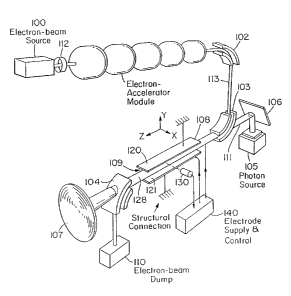
schematically in FIGURE 7 comprises an electron beam source
100, and an electron accelerator module 101, such as an
electron gun, an electron storage ring, a radiofrequency linac,
2 0 an introduction linac, an electrostatic accelerator, or a
microtron. The beam is focused by focusing means 112, such
as a magnetic or electrostatic lens, a solenoid, a quadrapole
magnet, or a laser beam. The electron beam 113, is directed
into a channel of electron guide 109, by beam directing
2 5 means 102 and 103, such as dipole magnets. Channel 109,
comprises a field generating means to produce a constant
electric or magnetic force in the direction opposite to
direction of the repulsive gravitational force. For example,
given that the repulsive gravitational force is negative z
3 0 directed as shown in FIGURE 7, the field generating means
109, provides a constant z directed electric force due to a
constant electric field in the negative z direction via a linear
potential provided by grid electrodes 108 and 128. Or, given
that the repulsive gravitational force is positive y directed as
3 5 shown in FIGURE 7, the field generating means 109, provides
a constant negative y directed electric force due to a constant
electric field in the negative y direction via a linear potential
WO 01/18948 CA 02383883 2002-03-05 PCT/US00/24471
32
provided by the top electrode 120, and bottom electrode 121,
of field generating means 109. The force provides work
against the gravitational field of the gravitating body as the
fundamental particle including an electron propagates along
the channel of the guide means and field producing means
109. The resulting work is transferred to the means to be
propelled via its attachment to field producing means 109.
The electric or magnetic force is variable until force
balance with the repulsive gravitational force may be
achieved. In the absence of force balance, the electrons will
be accelerated and the emittance of the beam will increase.
Also, the accelerated electrons will radiate; thus, the drop in
emittance and/or the absence of radiation is the signal that
force balance is achieved. The emittance and/or radiation is
detected by sensor means 130, such as a photomultiplier
tube, and the signal is used in a feedback mode by analyzer-
controller 140 which varies the constant electric or magnetic
force by controlling the potential or dipole magnets of (field
producing) means 109 to control force balance to maximize
2 0 the propulsion.
In one embodiment, the field generating means 109,
further provides an electric or magnetic field that produces
electrons of the electron beam 113 having a velocity surface
that is negatively curved. In another embodiment, electrons
2 5 of the electron beam 113 having a velocity surface are
produced by the absorption of photons provided by a photon
source 105, such as a high intensity photon source, such as a
laser. The laser radiation can be confined to a resonator
cavity by mirrors 106 and 107.
3 0 In a further embodiment, electrons from the electron
beam 113 having a velocity surface that is negatively curved
are produced by scattering with photons from the photon
source 105. The laser radiation or the resonator cavity is
oriented relative to the propagation direction of the electrons
3 5 such that the scattering cross section of the electron with the
photon to yield electrons having a velocity surface that is
negatively curved is maximized.
WO 01/18948 CA 02383883 2002-03-05 pCT/[JS00/24471
33
Following the propagation through the field generating
means 109 in which propulsion work is extracted from the
beam 113, the beam 113, is directed by beam directing
apparatus 104, such as a dipole magnet into electron-beam
dump 110.
In a further embodiment, the beam dump 110 is
replaced by a means to recover the remaining energy of the
beam 113 such as a means to recirculate the beam or recover
its energy by electrostatic deceleration or deceleration in a
radio frequency-excited linear accelerator structure. These
means are described by Feldman [10] which is incorporated
by reference.
The present invention comprises high current and high
energy beams and related systems of free electron lasers.
Such systems are described in Nuclear Instruments and
Methods in Physics Research [11-12] which are incorporated
herein by reference.
TRAJECTORY
2 0 In the case of a hyperbolic electron which is much
smaller then the size of a capacitor, the electric force of the
hyperbolic electron on the capacitor is equivalent to that of a
point charge. This force provides lift to the capacitor due to
the gravitational repulsion of the hyperbolic electron from
2 5 the Earth as it undergoes a trajectory through the capacitor.
A close approximation of the trajectory of hyperbolic
electrons generated by the propulsion means of the present
invention can be found by solving the Newtonian inverse-
square gravitational force equations for the case of a
3 0 repulsive force. The trajectory follows from the Newtonian
gravitational force and the solution of motion in an inverse-
square repulsive field given by Fowles [13]. The trajectory
can be calculated rigorously by solving the orbital equation
from the Schwarzschild metric (Eqs. (26.15-26.16)) for a two-
3 5 dimensional spatial velocity density function of negative
curvature which is produced by the apparatus and repelled
by the Earth. The rigorous solution is equivalent to that
WO 01/18948 CA 02383883 2002-03-05 PCT/US00/24471
34
given for the case of a positive gravitational velocity given in
the Orbital Mechanics Section of Mills [4] except that the
gravitational velocity is imaginary, or the gravitational radius
is negative.
In the case of a velocity function having negative
curvature, Eq. (23.78) becomes
2GM dt _ E
C1+ ~-_ (26.79)
rcz dz mcz
where M is the mass of the Earth and m is the mass of the
hyperbolic electron. Eq. (23.79) is based on the equations of
motion of the geodesic, which in the case of an imaginary
gravitation velocity or a negative gravitational radius
becomes
z a z z
Cdrl -_r CEl _Cl+2GM Le +mzcz (26.80)
d8 J LB c J c'r r
The repulsive central force equations can be transformed into
1 5 an orbital equation by the substitution, a = 1. The
r
relativistically corrected differential equation of the orbit of a
particle moving under a repulsive central force is
2
1 CEl z z
du z +uz = c J Lz m c - ~z z ~2GM~u _~2GM~u~ (26.81 )
(dal a J Ja
By differentiating with respect to B, noting that a = u(6) gives
dzu+u= GM-3C2GMluz (26.82)
d 8z a2 2 c Jz
where
Le
a=- (26.83)
m
In the case of a weak field,
C2GMlu c~ 1 (26.84)
c J_
2 5 and the second term on the right-hand of (26.37) can then be
neglected in the zero-order. The equation of the orbit is
uo= 1 =Acos(9+8o~_GM (26.85)
r a'
_ 1
' = GM (26.86)
A ~os(e + e° ) - ,
a-
WO 01/18948 CA 02383883 2002-03-05 PCT/US00/24471
where A and 9o denote the constants of integration. Consider
E,, the sum of the kinetic and gravitational potential energy:
E, = 1 rnvz + GMm (26.87)
2 r
where m is the mass of the hyperbolic electron. The orbit
5 equation may also be expressed in terms of E, as given by
Fowles [ 14]
az
r= GM ~ (26.88)
2Emaz z
-1 + 1 + z cos(9 - 90)
(GMm)
In a repulsive field, the energy is always greater than zero.
Thus, the eccentricity e, the coefficient of cos(9-6o), must be
1 0 greater than unity (e > 1) which requires that the orbit must
be hyperbolic. Consider the trajectory of a hyperbolic
electron shown in FIGURE 8. It approaches along one
asymptote and recedes along the other. The direction of the
polar axis is selected such that the initial position of the
1 5 hyperbolic electron is 8 = 0, r = ~. According to either of the
equations of the orbit (Eq. (26.86) or Eq. (26.88)) r assumes
its minimum value when cos(9 - 80) = l, that is, when 8 = 80.
Since r = ~ when B = 0, then r is also infinite when 8 = 290.
Therefore, the angle between the two asymptotes of the
2 0 hyperbolic path is 290, and the angle ~ through which the
incident hyperbolic electron is deflected is given by
~=~-280 (26.89)
Furthermore, the denominator of Eq. (26.88) vanishes when
8 = 0 and B = 29~ . Thus,
2Emaz z
25 -1+ 1+(GMm)'- cos(9~)=0 (26.90)
Using Eq. (26.89) and Eq. (26.90), the scattering angle ~ is
given in terms of 8 as
(2Em)z a
tan 90 = = cot ( 2 6 . 91 )
GMm 2
For convenience, the constant a = LH may be expressed in
nz
3 0 terms of another parameter P called the impact parameter.
WO 01/18948 CA 02383883 2002-03-05 PCT/US00/24471
36
The impact parameter is the perpendicular distance from the
origin (deflection or scattering center) to the initial line of
motion of the hyperbolic electron as shown in FIGURE 8. The
relationship between a the angular momentum per unit mass
and vo the initial velocity of the hyperbolic electron is
a=~rxv~=pvo (26.92)
A massive gravitational body such as the Earth will not be
moved by the encounter with a hyperbolic electron. Thus,
the energy E~ of the deflected hyperbolic electron is constant
1 0 and is equal to T the initial kinetic energy because the initial
potential energy is zero ( r = ~).
T=2mvo (26.93)
Using the impact parameter, the deflection or scattering
equation is given by
1 5 cot ~ _ pvo = 2pE (26.94)
2 GM GMm
= 2arctan ~~ ' = 2arctanC ~Mn~~ l (26.95 )
The gravitational velocity of the Earth vsc is approximately
v _ 2GM (26.96)
xr: ~ p
Thus, Eq. (26.95) is given by
z
2 0 ~ = 2arcta 2 v~E ( 2 6 . 9 7 )
0
Consider the postulate that the hyperbolic electron
must follow the trajectory for an inverse squared force in the
far field. In the limit, the far field trajectory is the
asymptote. As a method to obtain a first approximation of
2 5 the asymptote, consider the case that the hyperbolic electron
is generated at the surface of the Earth with an initial
trajectory as shown in FIGURE 8. The initial radial position is
Im~~ which is the radius of the Earth. Also, the impact
parameter p is essentially equal to the radius of the Earth.
3 0 Substitution of Eq. (26.87) and Eq. (26.92) into Eq. (26.91)
gores
WO 01/18948 CA 02383883 2002-03-05 pCT/US00/24471
37
2GM
vo + Pvo
GM =cot ~ (26.98)
Substitution of Eq. (26.96) into Eq. (26.98) gives
2(vo+v~t)2 v° =cot (26.99)
v~t_ 2
~ = 2arctan ~ v'~'' ~ ( 2 6 .10 0 )
vo + v~ f. ~ 2 vo
The gravitational velocity of the Earth v~, is
v, = 2RM =1.1X10 m/sec (26.101)
where R is the radius of the Earth. Consider the case of the
generation of hyperbolic electrons via elastic scattering from
helium atoms. Substitution of the hyperbolic electron
1 0 velocity of 2.187691 X 10~ mls given by Eq. (26.75) and the
gravitational velocity of the Earth given by Eq. (26.101 ) into
Eq. (26.100) gives
(1.1 X 10$ nz/sec)~
~ = 2arctan 1 ,
2 ((1.l X 108 m/sec)2 +(2.2 X 10~ m/sec~2~~(2.2 X 10~ nz/sec~
(26.102)
The angle of the asymptote is
~=175°=~c (26.103)
Thus, the asymptote of the trajectory of a hyperbolic electron
2 0 is essentially radial from the Earth. Since the trajectory in a
conservative inverse field is reversible going from -+-~ to -
or vice versa, the entire trajectory of a hyperbolic electron
with v~ = 2.187691 X 10~ zzz/s at m;~ equal to the radius of the
Earth is essentially radial with respect to the Earth. From this
2 5 result, it can be concluded that the far field trajectory of a
hyperbolic electron formed from a free electron with an
initial kinetic energy of 42.3 eV and an initial electron velocity
of 2.187691 X 10⁶ mls in an arbitrary initial direction relative to
WO 01/18948 CA 02383883 2002-03-05 PCT/US00/24471
38
the Earth is essentially radial from the Earth since l.) v~ is
much less than v~F, 2.) the impact parameter is essentially r",;n
which is the radius of the Earth since the radius of the Earth
is so large, and 3.) the free electron has zero gravitational
mass. The trajectory forms the gravitational boundary
condition to be matched with the additional scattering
boundary condition.
The scattering distribution of hyperbolic electrons given
by Eq. (26.51 ) is centered at a scattering angle of O" given by
1 0 Eq. (26.54). With the condition z~, = p", the elastic electron
scattering angle in the far field O~, is determined by the
boundary conditions of the curvature of spacetime due to the
presence of a gravitating body and the constant maximum
velocity of the speed of light. The far field condition must be
satisfied with respect to electron scattering and the
gravitational orbital equation. The former condition is met
by Eq. (26.51) and Eq. (26.54). The latter is met by Eq.
(26.103) where the far field angle of the hyperbolic
gravitational trajectory ~ is equivalent to 0~,.
2 0 The elastic scattering condition is possible due to the
large mass of the helium atom and the Earth relative to the
electron wherein the recoil energy transferred during a
collision is inversely proportional to the mass as given by Eq.
(2.70). Satisfaction of the far field conditions of the elastic
2 5 electron scattering to produce hyperbolic electrons and the
hyperbolic gravitational trajectory requires that the
hyperbolic electrons elastically scatter in a direction radially
from the Earth with a kinetic energy in the radial direction
that is essentially equal to the initial kinetic energy
3 0 corresponding to the condition z~, =p~,.
According to Eq. (23.48) and Eq. (23.140), matter,
energy, and spacetime are conserved with respect to creation
of the hyperbolic electron which is repelled from a
gravitating body, the Earth. The gravitationally ejected
3 5 hyperbolic electron gains energy as it is repelled ( > 10~ eV ).
The ejection of a hyperbolic electron having a negatively
curved velocity surface from the Earth must result in an
WO 01/18948 CA 02383883 2002-03-05 PCT/[JS00/24471
39
infinitesimal decrease in its radius of the Earth (e.g. r of the
Schwarzschild metric given by Eq. (26.2) where m0 = M is the
mass of the Earth). The amount that the gravitational
potential energy of the Earth is lowered is equivalent to the
energy gained by the repelled hyperbolic electron.
Momentum is also conserved for the electron, Earth,
and helium atom wherein the gravitating body that repels
the hyperbolic electron, the Earth, receives an equal and
opposite change of momentum with respect to that of the
electron.
Causing a satellite to follow a hyperbolic trajectory
about a gravitating body is a common technique to achieve a
gravity assist to further propel the satellite. In this case, the
energy and momentum gained by the satellite is also equal
and opposite that lost by the gravitating body.
The kinetic energy of the hyperbolic electron
corresponding to a velocity of 2.187691 X 10⁶ m l s is T = 42.3 eV .
Thus, 42.3 eV may be imparted to the propulsion means per
hyperbolic electron. With a beam current of 105 amperes
2 0 achieved in one embodiment by multiple beams such as 100
beams each providing 10~ amperes, the power transferred to
the device PAC is
P 105 coulomb X 1 electron X 42.3 eV X 1.6 X 10-'9J = 4,2 MW
Ac = sec 1.6 X 10-'~ coulombs electron eV
(26.104)
2 5 The power dissipated against gravity PC is given by
PC =m~gv~ (26.105)
where m~ is the mass of the craft, g is the acceleration of
gravity, v~ is the velocity of the craft. In the case of a 10~ kg
craft, the 4.2 MW of power provided by Eq. (26.104) sustains
3 0 a steady lifting velocity of 43 m/sec . Thus, significant lift is
possible using hyperbolic electrons.
In the case of a 10'~ kg craft, F~, the gravitational force is
Fx =m~_g=(10~ kg)C9.8 n~~~=9.8 X 10'' N (26.106)
sec
where m~ is the mass of the craft and g is the standard
3 5 gravitational acceleration. The lifting force may be
WO 01/18948 CA 02383883 2002-03-05 PCT/[JS00/24471
determined from the gradient of the energy which is
approximately the energy dissipated divided by the vertical
(relative to the Earth) distance over which it is dissipated.
The repulsive gravitational force provided by the hyperbolic
5 electrons may be controlled by adjusting the electric field of
the capacitor. For example, the electric field of the capacitor
may be increased such that the levitating force overcomes
the gravitational force. In an embodiment of the capacitor,
the electric field, E~~,~,, is constant and is given by the capacitor
10 voltage, V.~,~,, divided by the distance between the capacitor
plates, d, of a parallel plate capacitor.
E a,, = Va'' ( 2 6 .10 7 )
In the case that V~~p is 106 V and d is 1 m, the electric field is
6
Ecc',, = 10 V (26.108)
m
1 5 The force of the electric field of the capacitor on a hyperbolic
electron, Fm, is the electric field, E~~,~,, times the fundamental
charge
Fe,,, =eE~u~ =(1.6 X 10-'9 C~~106 vJ=1.6 X 10-'3 N (26.109)
m
The distance traveled away from the Earth, Dr_, by a
2 0 hyperbolic electron having an energy of
E = 42.3 eV = 6.77 X 10-'8 J is given by the energy divided by the
electric field F,P
-is
Qr _ E -_ 6.77 X 10 J = 4.23 X 10⁻⁵ m = 0.0423 mm
' F,e 1. 6 X 10-' 3 N
(26.110)
2 5 The number of electrons Ne is given by
Ne= I (26.111)
evf,r,.
where I is the current, a is the fundamental electron charge,
ve is the hyperbolic electron velocity, r, is the length of the
current. Substitution of I =105 A, ve = v0 = 2.187691 X 10⁶ rnls, and
3 0 r, =0.2 m, the number of electrons is
N, = 1.5 X 10' 8 electrons ( 2 6 .1 12 )
The repulsive gravitational force, F,,~, is given by multiplying
the number of electrons (Eq. (26.112)) by the force per
WO 01/18948 CA 02383883 2002-03-05 PCT/US00/24471
41
electron (Eq. (26.109)).
F,~~ = N~,F = (1.5 X 10'g electrons)(1.6 X 10-'3 N) = 2.4 X 10⁵ N ( 26.1 13 )
Thus, the present example of a propulsion device may
provide a levitating force that is capable of overcoming the
gravitational force on the craft to achieve a maximum vertical
velocity of 43 m/sec as given by Eq. (26.105). In an
embodiment of the propulsion device, the hyperbolic electron
current and the electric field of the capacitor are adjusted to
control the vertical acceleration and velocity.
Levitation by a repulsive gravitational force is orders of
magnitude more energy efficient than conventional rocketry.
In the former case, the energy dissipation is converted
directly to gravitational potential energy as the craft is lifted
out of the gravitation field. Whereas, in the case of rocketry,
1 5 matter is expelled at a higher velocity than the craft to
provide thrust or lift. The basis of rocketry's tremendous
inefficiency of energy dissipation to gravitational potential
energy conversion may be determined from the thrust
equation. In a case wherein external forces including gravity
2 0 are taken as zero for simplicity, the thrust equation is [15]
v=v°+Vlnm° (26.114)
rn
where v is the velocity of the rocket at any time, v° is the
initial velocity of the rocket, m° is the initial mass of the
rocket plus unburned fuel, m is the mass at any time, and V
2 5 is the speed of the ejected fuel relative to the rocket. Owing
to the nature of the logarithmic function, it is necessary to
have a large fuel to payload ratio in order to attain the large
speeds needed for satellite launching, for example.
The repulsive gravitational force of hyperbolic electrons
3 0 can be increased by using atoms of the neutral atom beam of
relativistic kinetic energy. The electrons of the electron beam
and the relativistic atoms of the neutral atomic beam
intersect at an angle such that the relativistically contracted
radius of each atom, z", is equal to p", the radius of each free
3 5 electron of the electron beam. Elastic scattering produces
hyperbolic electrons at relativistic energies. The relativistic
WO 01/18948 CA 02383883 2002-03-05 PCT/US00/24471
42
radius of helium is calculated by substitution of the
relativistic mass (Eq. (24.14)) of helium
m= "~° 2 (26..115)
1- v
c2
into Eq. (7.19) with a~, given by Eq. ( 1.168) where Eq.
(26.115) is transformed from Cartesian coordinates to
spherical coordinates. In a preferred embodiment, the
relativistic atomic beam which intersects the electron beam
directed along the negative x-axis is oriented at an angle of
to both the xz and yz-planes with the relativistic radius of
each neutral atom equal to the radius of each free electron.
In another embodiment, high energy hyperbolic
electrons are created by scattering according to Eq. (26.75)
and Eq. (26.78) from hydrino atoms of small radii. Since
hydrino atoms form hydrino hydride ions for p <_ 24, hydrino
1 5 atoms of p > 24 are preferably used.
In another embodiment shown in FIGURE 6, hyperbolic
electrons are accelerated to relativistic energies by an
acceleration means 7 before entering or within the capacitor
means 3 to provide relativistic hyperbolic electrons with
2 0 increased energy to be converted to gravitational potential
energy as the body to be levitated is levitated.
In the case of relativistic hyperbolic electrons, the
distance traveled in order to transfer a substantial amount of
the kinetic energy of the hyperbolic electron to an axis
2 5 parallel to that of the radius of the Earth is much greater than
the case of low hyperbolic electron velocities. With a
relativistic hyperbolic electron initially propagating in the
direction perpendicular to the radius of the Earth, a path
length of many meters may be required for the hyperbolic
3 0 electron to act on the capacitor. In one embodiment of the
propulsion device, a capacitor may further comprise a
synchrotron for forcing the hyperbolic electron in a orbit with
a component of the velocity in the xy-plane such as that
shown in FIGURE 9 which is perpendicular to the radius of
WO 01/18948 CA 02383883 2002-03-05 PCT/US00/24471
43
the Earth. The hyperbolic electron held in a synchrotron
orbit in the xy-plane is repelled by the Earth and transfers a
force to the capacitor in the z direction as shown in FIGURE 9.
In another further embodiment shown in FIGURE 6,
hyperbolic electrons of relativistic energy are produced by
the scattering of relativistic electrons of the electron beam 8
from the beam of neutrons 9 from the neutron source 12.
The relativistic radius of each electron equals the radius, rN,
of the neutron given by Eq. (28.10)
1 0 YN = h
(26.115a)
n2Nc
where nzN is the mass of the neutron. The relativistic electron
velocity is calculated from Eq. (26.44) and Eq. (26.115a)
where the mass of the electron is relativistically corrected by
substitution of the mass given by Eq. (26.115) into Eq.
(26.44).
v_ = jn~~ = c 1 z = .9999942c ( 2 6 .1 15 b )
a z r~' 1 + 27c me
1 _ vz mN
c
The relativistic kinetic energy, T, is
T=mecz 1 -1 (26.115c)
1- ~~~
c'
In the case of neutrons with the substitution of Eq. (26.115b)
2 0 into Eq. (26.115c),
T =149.0273 MeV ( 2 6 .1 15 d )
In a further embodiment, electrons from the electron
beam 113 of FIGURE 7 having a spatial velocity function
having negative curvature are formed by elastic scattering
2 5 with photons from the photon source 105. The wavelength of
each photon and the velocity of each electron is tuned such
that the radius of each photon is equal to the radius of each
electron. The relationship between the photon radius and
wavelength is given by
30 2m;,_~" (26.115a)
WO 01/18948 CA 02383883 2002-03-05 PCT/US00/24471
44
The relationship between the electron radius and velocity is
given by Eq. (26.43).
MECHANICS
In addition to levitation, acceleration in a direction
tangential to the gravitating body's surface can be effected
via conservation of angular momentum. Thus, a radially
accelerated structure such as an aerospace vehicle to be
tangentially accelerated possesses a cylindrically or
spherically symmetrically movable mass having a moment of
inertia, such as a flywheel device. The flywheel is rotated by
a driving device which provides angular momentum to the
flywheel. Such a device is the electron beams which are the
source of hyperbolic electrons. The electrons move
rectilinearly until being elastically scattered from an atomic
beam to form hyperbolic electrons which are deflected in a
radial direction from the center of the gravitating body. A
component to the initial momentum of the electron beam is
transferred to the gravitating body as the hyperbolic
2 0 electrons are deflected upward by the gravitating body. The
opposite momentum is transferred to the source of the
electron beam. This momentum may be used to translate the
craft in a direction tangential to the gravitating body's
surface or to cause it to spin. Thus, the electron beam serves
2 5 the additional function of a source of transverse or angular
acceleration. Thus, it may be considered an ion rocket.
The vehicle is levitated using propulsion means to
overcome the gravitational force of the gravitating body
where the levitation is such that the angular momentum
3 0 vector of the flywheel is parallel to the radial or central
vector of the gravitational force of the gravitating body. The
angular momentum vector of the flywheel is forced to make a
finite angle with the radial vector of gravitational force by
tuning the symmetry of the levitating forces provided by a
3 5 propulsion apparatus comprising multiple elements at
different spatial locations of the vehicle. A torque is
produced on the flywheel as the angular momentum vector is
WO 01/18948 CA 02383883 2002-03-05 PCT/US00/24471
reoriented with respect to the radial vector due to the
interaction of the central force of gravity of the gravitating
body, the repulsive gravitational force of the propulsion
means, and the angular momentum of the flywheel device.
5 The resulting acceleration which conserves angular
momentum is perpendicular to the plane formed by the
radial vector and the angular momentum vector. Thus, the
resulting acceleration is tangential to the surface of the
gravitating body.
10 Large translational velocities are achievable by
executing a trajectory which is vertical followed by a
precession with a large radius that gives a translation to the
craft. The latter motion is effected by tilting the spinning
craft to cause it to precess with a radius that increases due to
1 5 the force provided by the craft acting as an airfoil. The tilt is
provided by the activation and deactivation of multiple
repulsive gravitational devices of the present invention
spaced so that the desired torque perpendicular to the spin
axis is maintained. The craft also undergoes a controlled fall
2 0 and gains a velocity that provides the centrifugal force to the
precession as the craft acts as an airfoil. During the
translational acceleration, energy stored in the flywheel is
converted to kinetic energy of the vehicle. As the radius of
the precession goes to infinity the rotational energy is
2 5 entirely converted into transitional kinetic energy. The
equation for rotational kinetic energy ER and translational
kinetic energy ET are given as follows:
ER = 21cc~2 (26. 1 16)
where I is the moment of inertia and cc~ is the angular
3 0 rotational frequency;
ET = 1 rnv' (26.1 17)
2
where m is the total mass and v is the translational velocity
of the craft. The equation for the moment of inertia I of the
flywheel is given as:
35 I=~m;r= (26.118)
WO 01/18948 CA 02383883 2002-03-05 pCT/US00/24471
46
where m; is the infinitesimal mass at a distance r from the
center of mass. Eqs. (26.116) and (26.118) demonstrate that
the rotational kinetic energy stored for a given mass is
maximized by maximizing the distance of the mass from the
center of mass. Thus, ideal design parameters are cylindrical
symmetry with the rotating mass, flywheel, at the perimeter
of the vehicle.
The equation that describes the motion of the vehicle
with a moment of inertia I, a spin moment of inertial LS, a
1 0 total mass m, and a spin frequency of its flywheel of S is
given as follows [16]:
rnglsin8=18+ISS~sin9-I~'cos9sin9 (26.119)
o = I ~t ~c~sin 9J- I,S.S9 + l9~cos a ( 26.120)
p=I,SS (26.121)
where 8 is the tilt angle between the radial vector and the
angular momentum vector, 8 is the acceleration of the tilt
angle 8, g is the acceleration due to gravity, l is the height to
which the vehicle levitates, and ~ is the angular precession
frequency resulting from the torque which is a consequence
2 0 of tilting the craft. Eq. (26.121 ) shows that S, the spin of the
craft about the symmetry axis, remains constant. Also, the
component of the angular momentum along that axis is
constant.
L = I,~.S = constant ( 26.122 )
2 5 Eq. (26.120) is then equivalent to
0=~ (I~sin2B+I,~.Scos9) (26.123)
so that
l~sin' 8+ I,SScos9 = B = constant (26. 124)
The craft is an airfoil which provides the centrifugal force to
3 0 move the center of mass of the craft away from the Z axis of
the stationary frame. The schematic appears in FIGURE 10.
If there is no drag acting on the spinning craft to
dissipate its energy E, then the total energy E equal to the
kinetic T and potential V remains constant:
35 ,-t~(IcoX+Icc~+I,~S')+fnglcos9=E (26.125)
WO X1/18948 CA 02383883 2002-03-05 PCT/US00/24471
47
or equivalently in terms of Eulerian angles,
(19' + Iøz sin2 8 + ISSZ ) + mgl cos 9 = E ( 2 6 .12 6 )
From Eq. (26.124), ~ may be solved and substituted into Eq.
(26.126). The result is
1 ~2 (B-I,S.Scos9)Z 1
219 + 21sin29 +21SS +mglcos9=E (26.127)
which is entirely in terms of 8. Eq. (26.126) permits B to be
obtained as a function of time t by integration. The following
substitution may be made:
u=cose (26.128)
Then
i ., .
u=-(sin6)9=-(1-W) a (26.129)
Eq. (26.127) is then
u2 =(1-uz)(2E-I,sS2 -2mglu)1-' -~B-I,,.Su)21-z (26.130)
or
u'=f(u) (26.131)
from which a (hence 8) may be solved as a function of t by
integration:
t= f f~ ) (26.132)
a
2 0 In Eq. (26.132), f(u) is a cubic polynomial, thus, the
integration may be carried out in terms of elliptic functions.
Then the precession velocity ø may be solved may be solved
by substitution of 8 into Eq. (26.124) wherein the constant B
is the initial angular momentum of the craft along the spin
2 5 axis, I,,.S given by Eq. (26.122). The radius of the precession is
given by
R=lsin6 (26.133)
And the linear velocity v of the precession is given by
v = Rc~ ( 26.134)
3 0 The maximum rotational speed for steel is approximately
1100 mlsec [17]. For a craft with a radius of 10 m, the
110 cycles
corresponding angular velocity is . In the case that
sec
most of the mass of a 10~' kg was at this radius, the initial
WO ~l/18948 CA 02383883 2002-03-05 PCT/US00/24471
48
rotation energy (Eq. (26.116)) is 6 X 10⁹ J. As the craft tilts
and changes altitude (increases or decreases), the airfoil
pushes the craft away from the axis that is radial with
respect to the Earth. For example, as the craft tilts and falls,
the airfoil pushes the craft into a trajectory which is
analogous to that of a gyroscope as shown in FIGURE 10.
From FIGURE 10, the centrifugal force provided by the airfoil
( mgcos9) is always less than the force of gravity on the craft.
From Eq. (26.124), the rotational energy is transferred from
the initial spin to the precession as the angle 8 increases.
From Eq. (26.125), the precessional energy may become
essentially equal to the initial rotational energy plus the
initial gravitational potential energy. Thus, the linear
velocity of the craft may reach approximately 1100 m/sec
1 5 ( 2500 mph). During the transfer, the craft falls approximately
one half the distance of the radius of the precession of the
center of mass about the Z axis. Thus, the initial vertical
height l must be greater.
In the cases of solar system and interstellar travel,
2 0 velocities approaching the speed of light may be obtained by
using gravity assists from massive gravitating bodies wherein
the capability of the craft to provide a repulsive gravitational
force establishes the desired trajectory to maximize the
assist.
EXPERIMENTAL
The electron-impact energy-loss spectrum of helium
taken in the forward direction with 100 eV incident electrons
with a resolution of 0.15 eV by Simpson, Mielczarek, and
3 0 Cooper [18] showed large energy-loss peaks at 57.7 eV, 60.0 eV,
and 63.6 eV. Resonances in the photoionization continuum of
helium at 60 eV and in the 63.6 eV region have been observed
spectroscopically by Madden and Codling [19] using
synchrotron radiation. Absent was a resonance at 57.7 eV.
3 5 Both Simpson and Madden assign the peaks of their data to
two-electron excitation states in helium. Each of these states
decays with the emission of an ionization electron of energy
WO X1/18948 CA 02383883 2002-03-05 PCT/USO~/24471
49
equal to the excitation energy minus the ionization energy of
helium, 24.59 eV. The data of Goruganthu and Bonham [20]
shows ejected-energy peaks at 35.5 eV and at 39.1 eV
corresponding to the energy loss peaks of Simpson of 60.0 eV
and 63.6 eV, respectively. The absence of an ejected-energy
peak corresponding to the energy-loss peak at 57.7 eV
precludes the assignment of this peak to a two-electron
resonance. The energy of each inelastically scattered electron
of incident energy of 100 eV corresponding to the energy-loss
1 0 of 57.7 eV is 42.3 eV. This is the resonance energy of
hyperbolic electron production by electron scattering from
helium given by Eq. (26.77). Thus, the 57.7 eV energy-loss
peak of Simpson arises from inelastic scattering of electrons
of 42.3 eV from helium with resonant hyperbolic electron
production. The production of electrons with velocity
functions having negative curvature is experimentally
supported.
The electron-impact energy-loss spectrum of helium
taken in the forward direction with 400 eV incident electrons
by Priestley and Whiddington [21] showed large energy-loss
peaks at 42.4 eV, and 60.8 eV. A resonance in the
photoionization continuum of helium at 60 eV has been
observed spectroscopically by Madden and Codling [ 19] using
synchrotron radiation. Absent was a resonance at 42.4 eV .
2 5 Both Priestley and Madden assign the peaks of their data to
two-electron excitation states in helium. Each of these states
decay with the emission of an ionization electron of energy
equal to the excitation energy minus the ionization energy of
helium, 24.59 eV. The data of Goruganthu and Bonham [20]
3 0 shows an ejected-energy peak at 35.5 eV corresponding to the
energy loss peak of Priestley of 60.8 eV . The absence of an
ejected-energy peak at 17.8 eV corresponding to the energy-
loss peak at 42.4 eV precludes the assignment of this peak to a
two-electron resonance. This is the resonance energy of
3 5 hyperbolic electron production by electron scattering from
helium given by Eq. (26.77). Thus, the 42.4 eV energy-loss
peak of Priestley arises from inelastic scattering of electrons
WO 01/18948 CA 02383883 2002-03-05 PCTNS00/24471
of 42.3 eV from helium with resonant hyperbolic electron
production. The production of electrons with velocity
functions having negative curvature is experimentally
further supported.
5 References
1. Adelberger, E. G., Stubbs, C.W., Heckel, B.R., Su, Y., Swanson,
H.E., Smith, G., Gundlach, J. H., Phys. Rev. D, Vol. 42, No. 10,
( 1990), pp. 3267-3292.
2. R. M. Wald, General Relativity, University of Chicago Press,
10 Chicago, (1984), pp. 91-101.
3. N. A. Bahcall, J. P. Ostriker, S. Perlmutter, P. J. Steinhardt,
Science, May 28, 1999, Vol. 284, pp. 1481-1488.
4. R. Mills, The Grand Unified Theory of Classical Quantum
Mechanics, January 2000 Edition, BlackLight Power, Inc.,
15 Cranbury, New Jersey, Distributed by Amazon.com.
5. Fock, V., The Theory of Space, Time, and Gravitation, The
MacMillan Company, ( 1964).
6. Fang , L. Z., and Ruffini, R., Basic Concepts in Relativistic
Astronh, sy ics, World Scientific, (1983).
2 0 7. Fowles, G. R., Analytical Mechanics, Third Edition, Holt,
Rinehart, and Winston, New York, (1977), pp. 154-155.
8. Witteborn, F. C., and Fairbank, W. M., Physical Review
Letters, Vol. 19, No. 18, (1967), pp. 1049-1052.
9. Bonham, R. F., Fink, M., High Energy Electron Scattering,
2 5 ACS Monograph, Van Nostrand Reinhold Company, New
York, ( 1974).
10. Feldman, D. W., et al., Nuclear Instruments and Methods
in Physics Research, A259, 26-30 ( 1987).
11. Nuclear Instruments and Methods in Physics Research,
3 0 A272, (1,2), 1-616 (1988).
12. Nuclear Instruments and Methods in Physics Research,
A259, (1,2), 1-316 (1987).
13. Fowles, G. R., Analytical Mechanics, Third Edition, Holt,
Rinehart, and Winston, New York, (1977), pp. 140-164.
3 5 14. Fowles, G. R., Analytical Mechanics, Third Edition, Holt,
Rinehart, and Winston, New York, (1977), pp. 154-160.
15. Fowles, G. R., Analytical Mechanics, Third Edition, Holt,
WO 01/18948 CA 02383883 2002-03-05 PCT/US00/24471
1
Rinehart, and Winston, New York, (1977), pp. 182-184.
16. Fowles, G. R., Analytical Mechanics, Third Edition, Holt,
Rinehart, and Winston, New York, (1977), pp. 243-247.
17. J. W. Beams, "Ultrahigh-Speed Rotation", pp. 135-147.
5 18. Simpson, J. A., Mielczarek, S. R., Cooper, J., Journal of the
Optical Society of America, Vol. 54, (1964), pp. 269-270.
19. Madden, R. B., Codling, K., Astrophysical Journal, Vol. 141,
( 1965), pp. 364-375.
20. Goruganthu, R. R., Bonham, R. A., Physical Review A, Vol.
34, No. 1, (1986), pp. 103-125.
21. Priestley, H., Whiddington, R., Proc. Leeds Phil. Soc., Vol. 3,
( 1935), p. 81.