Note: Descriptions are shown in the official language in which they were submitted.
CA 02384179 2002-03-06
WO 01/20697 PCT/US00/22603
METHOD OF ACTIVATING METAL HYDRIDE MATERIAIr AND EhECTRODE
FIELD OF THE INVENTION
The present invention relates to rechargeable hydrogen
storage electrochemical cells. More particularly, the invention
relates to a method of activating hydrogen storage alloy
materials and hydrogen storage alloy electrodes.
BACKGROUND OF THE INVENTION
Rechargeable electrochemical cells using a hydrogen
storage alloy as the active material for the negative electrode
are known in the art. The negative electrode is capable of the
reversible electrochemical storage of hydrogen. The positive
electrode typically comprises a nickel hydroxide active
material although other active materials, such as manganese
hydroxide, may be used. The negative and positive electrodes
are spaced apart in an alkaline electrolyte. A suitable
separator (i.e., a membrane) may also be positioned between the
electrodes. As used herein the terminology "metal hydride
material", "hydrogen storage alloy", and "hydrogen absorbing
alloy" are synonymous.
Upon application of an electrical current to the negative
electrode, the active metal hydride material is charged by the
absorption of hydrogen. This is shown by reaction (1).
M + HZO + a -> M-H + OH (Charging) (1)
Upon discharge, the stored hydrogen is released by the metal
hydride material to provide an electric current. This is shown
by reaction (2).
M-H + OH -> M + H20 + a (Discharging) (2)
The reactions at a conventional nickel hydroxide positive
electrode as utilized in a nickel-metal hydride electrochemical
1
CA 02384179 2002-03-06
WO 01/20697 PCT/US00/22603
cell are as follows:
Ni (OH) 2 + OH- -> Ni00H + H20 + a (Charging) (3)
Ni00H + HZO + a -> Ni(OH)2 + OH (Discharging) (4)
Based on the pioneering principles of Stanford R.
Ovshinsky, a family of extremely efficient electrochemical
hydrogen storage materials were formulated. These are the
Ti-V-Zr-Ni type active materials such as those disclosed in
U.S. Patent No. 4,551,400 ("the '400 Patent") the disclosure of
which is incorporated herein by reference. These materials
reversibly form hydrides in order to store hydrogen. All the
materials used in the '400 Patent utilize a generic Ti-V-Ni
composition, where at least Ti, V, and Ni are present with at
least one or more of Cr, Zr, and A1.
Other examples of metal hydride alloys are provided in
U.S. Patent No. 4,728,586 ("the '586 Patent") the disclosure of
which is incorporated herein by reference. The '586 Patent
describes a specific sub-class of these Ti-V-Ni-Zr alloys
comprising Ti, V, Zr, Ni, and a fifth component, Cr. The '586
patent, mentions the possibility of additives and modifiers
beyond the Ti, V, Zr, Ni, and Cr components of the alloys, and
generally discusses specific additives and modifiers, the
amounts and interactions of these modifiers, and the particular
benefits that could be expected from them. Still other
examples of hydrogen absorbing alloys are provided in U.S.
Patent No. 5,536,591 ("the '591 Patent"), the disclosure of
which is incorporated herein by reference. In particular, the
' 591 Patent provides teaching on the type of surface interface
at the metal hydride electrode and the nature of catalytic
sites ideal for promoting high rate discharge.
In part, due to the research into the negative electrode
active materials, the Ovonic nickel-metal hydride batteries
have demonstrated excellent performance characteristics such as
power, capacity, charging efficiency, rate capability and cycle
2
CA 02384179 2002-03-06
WO 01/20697 PCT/US00/22603
life. Presently, there is an increasing use of rechargeable
nickel-metal hydride batteries in all types of portable tools,
appliances, and computer devices. As well, there is a growing
use of nickel-metal hydride cells in applications such as
electric and hybrid-electric vehicles. Many of the new uses
for the nickel-metal hydride cells require that further
improvements be made in the cell's performance.
Many of the performance characteristics of a nickel-metal
hydride cell are affected by the surface conditions of the
active metal hydride material used in the cell's negative
electrode. For example, the power of the cell is affected by
both the surface composition and the surface area of the metal
hydride material. The appropriate modification of the surface
composition and/or the surface area can change the surface
kinetics of the hydride reaction so as to lower the charge
transfer resistance of the material.
Hydrogen storage alloys are sensitive to the formation of
oxides and the alloy surfaces comprise, to a great extent,
metal oxides. The composition of these oxides depends on many
factors including the composition, morphology and method of
preparation of the hydrogen storage alloy. Generally, the type
of surface oxides which form naturally and not by design may be
detrimental to the performance of the negative electrode and
cell. Oxides at the surface of the hydrogen absorbing alloy
decreases the alloy's catalytic (charge transfer) capabilities,
thereby decreasing both the charging and discharging efficiency
of the electrode and cell.
During cell charging, the decreased surface kinetics of
the alloy shifts the potential at the surface of the electrode
so as to increase the evolution of hydrogen gas via the
hydrogen evolution reaction:
2H20 + 2e- ----> H2 + 20H- (5)
Atomic hydrogen formed at the surface of the negative
3
CA 02384179 2002-03-06
WO 01/20697 PCT/US00/22603
electrode can either recombine with another atomic hydrogen and
escape as molecular hydrogen gas or it can react with the
hydrogen absorbing alloy in the electrode to form a hydride.
If the surface of the hydrogen absorbing alloy is covered with
oxides, hydride formation is inhibited and hydrogen evolution
is preferred. Electric current (e.g., electrons) applied to
the negative electrode for the purpose of charging the
electrode via charging reaction (1) is instead "wasted" in the
production of hydrogen gas via reaction (5). This decreases
the charging efficiency of the cell and increases the pressure
of hydrogen gas within the cell. The decreased surface
kinetics also increases the charge transfer resistance of the
material and the electrode so that more power is wasted due to
internal dissipation. It is also believed that the surface
oxides polarize the electrode so as to reduce the rate at which
the cell discharge process proceeds.
Many of the surface oxides are very dense and impermeable
to hydrogen transfer thereby increasing the resistance to
hydrogen diffusion during both the charging and discharging
processes. This has a detrimental effect on the rate
capability of the electrode.
U.S. Patent No. 4,716,088, the contents of which is
incorporated by reference herein, describes a method of
"activating" the hydrogen storage alloy material by immersing
the material into a alkaline solution. This "alkaline etch
treatment" modifies the composition and morphology of the alloy
surface so as to improve the electrochemical activity of the
alloy and the electrodes formed from the alloy.
The activation process modifies the composition of the
oxide layer on the surface of the alloy. The oxide composition
depends upon the composition of the underlying hydrogen storage
alloy as well as the corrosivity of the different metals which
form the alloy. Certain metals such as titanium, zirconium and
manganese have a greater affinity for oxidation while other
metals such as nickel do not oxidize as readily. Oxide
4
CA 02384179 2002-03-06
WO 01/20697 PCT/US00/22603
composition may also depend upon the specific process used to
make the alloy since certain processes may promote oxidation
more than others.
It is believed that immersing the hydrogen storage alloy
into the alkaline solution at least partially dissolves certain
oxides from the alloy surface. The extent of dissolution
depends upon the solubility of the specific oxide in the
alkaline environment. Certain oxides, such as oxides of
manganese, vanadium, aluminum and cobalt are readily soluble in
an alkaline solution while others, such as those of titanium,
zirconium and nickel are less soluble.
The alkaline etch treatment modifies the oxide composition
of the alloy surface so as to increase the catalytic activity
(charge transfer capabilities) of the material. While not
wishing to be bound by theory, it is believed that the
activation process increases the concentration of nickel metal
at or near the alloy's surface. Increasing the catalytic
activity of the alloy surface lowers the charge transfer
resistance of the material and electrode. The lowered
resistance results in more efficient battery discharge since
there is less power wasted due to internal dissipation and more
power available for battery output. The lowered resistance
also increases the charging efficiency of the cell since it
shifts the voltage on the surface of the negative electrode
away from the hydrogen evolution potential.
Activation also provides for a "gradual transitioning" in
the composition and/or oxidation state of the oxide layer from
the electrolyte/oxide interface to the bulk material. For
example, the oxide layer after activation may have a small
concentration of soluble components near the electrolyte
interface but a composition more closely resembling the bulk
material further away from the interface. This "gradient-type"
surface may have an electrical and catalytic nature which is
more suitable for electrochemical charging and discharging.
The activation process disclosed in the '088 Patent
5
CA 02384179 2002-03-06
WO 01/20697 PCT/US00/22603
describes an alkaline etch treatment wherein the temperature of
the alkaline solution as well as the time in which the hydrogen
storage alloy is left in contact with the alkaline solution are
both variables that affect the results of the process. The
present invention describes an alkaline etch treatment of a
hydrogen absorbing alloy and an alkaline etch treatment of a
hydrogen absorbing alloy electrode wherein the concentration of
the alkaline solution is also a result-effective variable which
can be varied to provide an activated hydrogen storage alloy
and an activated hydrogen storage alloy electrode with
increased surface area and improved electrochemical properties.
SUi~ARY OF THE INVENTION
One objective of the present invention is an improved
method of activating a hydrogen storage alloy and/or a hydrogen
storage alloy electrode. Another objective of the present
invention is a hydrogen storage alloy with increased surface
area. Yet another object of the present invention is a
hydrogen storage alloy electrode with decreased internal
resistance and increased output power. Yet another objective
of the present invention is a hydrogen storage alloy electrode
with improved rate capability.
These and other objectives are satisfied by a method of
activating a hydrogen storage alloy, comprising the step of:
contacting the hydrogen storage alloy with an aqueous solution
of an alkali metal hydroxide having a concentration of at least
about 40 weight percent.
These and other objectives are also satisfied by a method
of activating a hydrogen storage alloy electrode for an
alkaline electrochemical cell, comprising: contacting the
electrode with an aqueous solution of an alkali metal hydroxide
having a concentration of at least about 40 weight percent.
These and other objectives are also satisfied by hydrogen
storage alloy having a surface area of at least 4 square meter
6
CA 02384179 2002-03-06
WO 01/20697 PCT/US00/22603
per gram achieved without electrochemical cycling.
These and other objectives are also satisfied by a
hydrogen storage alloy electrode, comprising: a hydrogen
storage alloy affixed to a conductive substrate, the electrode
having a surface area of at least 4 square meter per gram
achieved without electrochemical cycling.
These and other objectives are also satisfied by a process
for making a hydrogen absorbing alloy electrode, comprising the
steps of: contacting a hydrogen absorbing alloy with an aqueous
solution of an alkali metal hydroxide having a concentration of
at least about 40 weight percent; and affixing the hydrogen
absorbing alloy onto a conductive substrate.
These and other objectives are also satisfied by a process
for making a hydrogen absorbing alloy electrode, comprising the
steps of: affixing a hydrogen absorbing alloy onto a conductive
substrate to form an unactivated electrode; and contacting the
unactivated electrode with an aqueous solution of an alkali
metal hydroxide having a concentration of at least 40 weight
percent.
BRIEF DESCRIPTION OF THE DRAWINGS
Figure 1 is the potential-pH equilibrium diagram for the
system zirconium-water at 25°C;
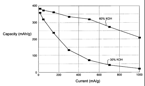
Figure 2 shows rate capability curves for electrodes
activated at a temperature of 100°C at 30 weight percent KOH
and 60 weight percent KOH; and
Figure 3 shows rate capability curves for electrodes
activated at a temperature of 110°C at 30 weight percent KOH,
45 weight percent KOH and 60 weight percent KOH.
DETAI7~ED DESCRIPTION OF THE INVENTION
Disclosed herein is a method of activating a hydrogen
storage alloy and a method of activating a hydrogen absorbing
alloy electrode. The activation methods of the present
invention are referred to "alkaline etch treatments" whereby a
7
CA 02384179 2002-03-06
WO 01/20697 PCT/US00/22603
hydrogen absorbing alloy material or a hydrogen absorbing alloy
electrode (comprising said material) is contacted with an
alkaline solution. Preferably, the alkaline solution is a
highly concentrated aqueous solution of an alkali metal
hydroxide.
First, a method of activating a hydrogen absorbing alloy
is described. Generally, the method of activation comprises
the step of contacting the hydrogen storage alloy with an
alkaline solution. Preferably, the alkaline solution is an
aqueous solution of an alkali metal hydroxide where the
concentration of the alkali metal hydroxide is at least about
40 weight percent. The hydrogen storage alloy may be
"contacted" with the alkaline solution by immersing the
hydrogen storage alloy into a container of the alkaline
solution. The hydrogen storage alloy may be in the form of a
powder.
After the hydrogen absorbing alloy is contacted with the
alkaline solution for a sufficient time (a "sufficient" time is
preferably a time sufficient to alter the surface oxides so as
to increase the surface kinetics of the hydrogen absorbing
alloy material), the hydrogen absorbing alloy may be separated
from the alkaline solution (for example, by filtration), washed
(for example, with deionized water) and dried. The material
may then be affixed to a conductive substrate to form a
hydrogen storage alloy electrode. The substrate may be any
conductive support for the hydrogen absorbing alloy material.
Examples of substrates include expanded metal, screen, mesh,
foil, foam, and plate. The substrates may be formed from
conductive materials such as nickel or a nickel alloy, and
copper or a copper alloy. The material may be affixed to the
substrate by compaction, such as by one or more rolling mills.
Alternatively, the material may be pasted onto the substrate.
The electrode may be used as the negative electrode in an
alkaline electrochemical cell such as a nickel-metal hydride
electrochemical cell.
8
CA 02384179 2002-03-06
WO 01/20697 PCT/US00/22603
Also disclosed herein is a method of activating a hydrogen
storage alloy electrode. A hydrogen storage alloy electrode
comprises a hydrogen storage alloy as the active electrode
material. The hydrogen storage alloy electrode may be formed
by affixing a hydrogen storage alloy powder onto a conductive
substrate. As discussed, the hydrogen storage alloy powder may
be affixed to the substrate by methods such as compaction or
pasting. The method of activating a hydrogen storage alloy
electrode comprises the step of contacting the electrode with
an alkaline solution. Preferably, the alkaline solution is an
aqueous solution of an alkali metal hydroxide where the
concentration of the alkali metal hydroxide is at least about
40 weight percent.
The contacting step is preferably done prior to sealing
the electrode inside an electrochemical cell. For example, the
electrode may be "contacted" with the alkaline solution by
immersing the electrode into a container of the alkaline
solution. After the electrode is contacted with the alkaline
solution for a sufficient period of time (a "sufficient time is
preferably a period of time sufficient to alter the surface
oxides so as to increase the surface kinetics of the hydrogen
absorbing alloy electrode), the electrode is removed from the
alkaline solution. It may then be washed (for example, with
deionized water) and then dried. It may then be used as an
electrode for an electrochemical cell (preferably as a negative
electrode for an alkaline electrochemical cell such as a
nickel-metal hydride electrochemical cell).
The contacting step may also be done after the electrode
is sealed inside the electrochemical cell. For example, the
electrode may first be sealed inside an electrochemical cell
and then be activated by an alkaline solution inside the cell.
The alkaline solution used to activate the hydrogen
absorbing alloy and/or the hydrogen absorbing alloy electrode
is a "concentrated" alkaline solution which is preferably an
9
CA 02384179 2002-03-06
WO 01/20697 PCT/US00/22603
aqueous solution of an alkali metal hydroxide having a
concentration which is at least about 40 weight percent.
Preferably, the concentration of the alkali metal hydroxide is
between about 40 weight percent and about 70 weight percent.
More preferably, the concentration of the alkali metal
hydroxide is between about 50 weight percent and about 70
weight percent. Most preferably, the concentration of the
alkali metal hydroxide is between about 55 weight percent and
about 65 weight percent. It is noted that the alkaline solution
preferably has an alkali metal hydroxide concentration which is
greater than the concentration which will dissolve in water at
room temperature. Such highly concentrated alkaline solutions
are not typically available commercially as "off-the-shelf"
products. Instead, they must be made by dissolving a solid
alkali metal hydroxide into a container of heated water.
Examples of alkali metal hydroxides which may be used
include potassium hydroxide (KOH), sodium hydroxide (NaOH), and
lithium hydroxide (LiOH). Mixtures of potassium hydroxide,
sodium hydroxide, and lithium hydroxide may also be used.
Preferably, the alkali metal hydroxide is potassium hydroxide.
In addition to the concentration of the alkali metal
hydroxide, the results of the activation process are also
dependent upon the temperature of the alkaline solution as well
as the time in which the alkaline solution is permitted to
contact the hydrogen absorbing alloy material. The actual
temperature and time conditions used in the activation process
depends upon many factors. Examples of such factors include
oxide composition, oxide concentration, the composition of the
hydrogen absorbing alloy material being etched, the composition
of the hydrogen absorbing alloy electrode being etched, the
composition of the alkali metal hydroxide used, and the
concentration of the alkali metal hydroxide used in the
alkaline solution. Typically, a higher concentration of the
alkali metal hydroxide requires a higher temperature to ensure
CA 02384179 2002-03-06
WO 01/20697 PCT/US00/22603
adequate solubility of the alkali metal hydroxide in the
aqueous solution. With concentrations of the alkali metal
hydroxide of at least 40 weight percent, the temperature of the
alkaline solution is preferably at least about 60°C, more
preferably at least about 80°C, and most preferably at least
about 100°C. An additional preferable range is between 105°C
and 155°C. The time of activation is preferably a time which
is sufficient to alter the surface oxides so as to increase the
surface kinetics of the hydrogen absorbing alloy and/or the
hydrogen absorbing alloy electrode. The time of activation may
be between about one hour and about five hours.
As discussed above, the '088 Patent describes an alkaline
etch treatment process wherein the temperature of the alkaline
solution as well as the time period in which the alloy or
electrode is left in contact with the alkaline solution are
both variables which affect the electrochemical behavior of the
alloy and/or electrode. The alkaline etch treatments of the
present invention are distinguishable from what is described in
the '088 Patent. The present inventors have discovered that
the alkali metal hydroxide concentration of the alkaline
solution is also a result-effective variable which may be
modified to remarkably and unexpectedly improve the activation
processes. In particular, the instant inventors have
discovered that an alkaline etch treatment using an alkali
metal hydroxide concentration of at least about 40 weight
percent provides for an unexpected increase in the surface area
of the hydrogen storage alloy and/or the hydrogen storage
electrode beyond that which can be achieved through variations
in time and temperature alone.
While not wishing to be bound by theory, it is believed
that the increased surface area of the hydrogen storage alloy
is due, at least in part, to an increase in the solubility of
the metal oxides with the increased pH of the alkaline solution
used to perform the
alkaline etch treatment of the present invention. Generally,
11
CA 02384179 2002-03-06
WO 01/20697 PCT/US00/22603
the solubility of a metal oxide in an alkaline solution
increases with the pH of the solution. This may be seen by
referring to Figure 1 which shows the potential-pH equilibrium
diagram for the system zirconium-water at 25°C. The
dissolution of zirconium oxide ZrOz (zirconia) into zirconate
ions HZr03 may be expressed by the chemical reaction (6):
ZrOz + OH -> HZr03- (6)
Increasing the concentration of an alkali metal hydroxide,
such as potassium hydroxide, in the alkaline solution increases
the OH- concentration in the solution, driving reaction (6) to
the right and increasing the dissolution of the oxide. Lines A
and B of Figure 1 are the pH-potential equilibrium lines
corresponding to the dissolution of the zirconium oxide (as
expressed by reaction (6)). They show that the solubility of
zirconia increases with pH. (For example, increasing the weight
percentage of the alkali metal hydroxide from about 30 weight
percent to about 60 weight percent increases the pH of the
alkaline solution by about 0.3 pH units, doubling the
solubility of the zirconium oxide).
The increase in pH of the alkaline solution increases the
solubility of the zirconium oxide and removes more of the
soluble oxide components from the surface of the alloy, thereby
increasing its porosity and surface area. The increase in pH
also removes some of the less soluble oxide components (i.e.,
oxides such as titanium oxide and chromium oxide that were
negligibly soluble in a 30 weight percent KOH solution),
thereby further increasing the porosity and surface area as
well as causing changes in the composition of the oxide layer.
Again, while not wishing to be bound by theory, it is
further believed that the increased surface area of the
hydrogen storage alloy is also due to increased electrochemical
corrosion of the unoxidized metal species of the hydrogen
storage alloy. For example, the corrosion of zirconium metal
12
CA 02384179 2002-03-06
WO 01/20697 PCT/US00/22603
to zirconate ions HZr03- may be expressed as the electrochemical
oxidation-reduction reaction (7):
Zr + OH- + 2Hz0 ------> HZr03 + 2H2(gas) (7)
As seen from reaction (7), the oxidation of zirconium metal to
zirconate ions HZr03- is accompanied by the reduction of
hydrogen ions to hydrogen gas.
The oxidation-reduction reaction (7) may be written as two
separate reactions (7a) and (7b) for the oxidation of zirconium
metal and the reduction of hydrogen ions, respectively:
Zr + 50H- --------> HZr03 + 2H20 + 4e (7a)
4H20 + 4e- --------> 2H2(gas) + 40H- (7b)
The standard electrode potential E° of the oxidation reaction
(7a) is measured relative to the potential of the standard
hydrogen electrode reaction (7b). Generally, metals which are
more reactive than hydrogen are assigned negative values of E°
and are said to be "anodic" to hydrogen. Furthermore, the
larger the negative potential relative to hydrogen, the more
reactive the metal.
With this in mind, the reader is again referred to Figure
1. Line C is the pH-potential equilibrium line corresponding
to the oxidation half-cell reaction (7a) of zirconium metal to
zirconate ions HZr03 . Line D is the pH-potential line
corresponding to the reduction half-cell reaction (7b) of
hydrogen ions to hydrogen gas.
As may be observed, at sufficiently high values of pH,
increases in the pH makes the potential of the oxidation
reaction (7a) more negative relative to the reduction reaction
(7b) so that zirconium metal becomes more reactive relative to
hydrogen. Hence, increases in pH increases the corrosion of
the zirconium metal (oxidation reaction 7a) as well as the
evolution of hydrogen gas (reduction reaction 7b). Increased
13
CA 02384179 2002-03-06
WO 01/20697 PCT/US00/22603
evolution of hydrogen gas increases hydrogen gas pressure.
This causes greater penetration of the hydrogen gas into the
hydrogen storage alloy resulting in cracking and breakage of
the alloy particles and increasing the surface area of the
material. The penetration of the hydrogen gas into the
hydrogen storage alloy also causes partial charging of the
alloy. (For example, increasing the alkali metal hydroxide
concentration, such as KOH, from about 30 wto to about 60 wt%
increases the pH of the alkaline solution by about 0.3 pH
units. This increases the potential difference between the two
half-cell reactions (7a) and (7b) by about 30 mV and increases
the evolution of hydrogen gas sufficiently to increase the
hydrogen gas pressure by about a factor of ten).
It is noted that an alkali metal hydroxide concentration
below about 40 weight percent does not provide for a sufficient
increase in either the dissolution of the metal oxide species
nor the corrosion of the metal to significantly affect the
surface area of either the hydrogen absorbing alloy or hydrogen
absorbing alloy electrode. As well, an alkali metal hydroxide
concentration above about 70 wt% may be undesirable since they
may be difficult to dissolve such a high concentration of
alkali metal hydroxide without further increases in
temperature. Hence, it is preferable that the alkali metal
hydroxide concentration is below about 70 wto, and more
preferably that the alkali metal hydroxide concentration is
below about 65 wto.
EXAMPLE 1 - ALLOY ACTIVATION/BET ANALYSIS
A sample of a hydrogen storage alloy powder having the
composition Zrzs.sTi9V5Cr5Mn16Ni38Sno.a is subjected to an alkaline
etch treatment by being immersed in a 30 wto KOH aqueous
solution, at about 110°C, for a time period of about four and
one-half hours. A second sample of the same alloy powder is
immersed in a 45 wt o KOH aqueous solution, at about 110°C, for
about three hours. A third sample of the same alloy powder is
14
CA 02384179 2002-03-06
WO 01/20697 PCT/US00/22603
immersed in a 60 wt o KOH aqueous solution, at about 110°C, for
about two hours. The Samples are separated from the KOH
solutions, rinsed with deionized water, and dried.
The surface area of the powders are measured using BET
analysis. The BET results are shown in Table 1 for the 30 wt%,
45 wto, and 60 wto alkaline etch treatments. It is noted that
the surface areas listed in the table are achieved without any
electrochemical cycling.
TABLE 1 - POWDER SURFACE AREA (BET MEASUREMENT)
ALKALINE ETCH TREATMENT WITHOUT ELECTROCHEMICAL CYCLING
oWt KOH Temp Time BET Surface Area
30% 110°C 4.5 hr 3.2 mz/g
45 0 110°C 3 . 0 hr 5 . 9 m2/g
60% 110°C 2. 0 hr 6. 3 m2/g
EXAMPLE 2 - ELECTRODE ACTIVATION/BET ANALYSIS
Samples of the same hydrogen storage alloy used in Example
1 are compacted onto conductive substrates to form electrodes.
A first electrode is subjected to the alkaline etch treatment
at a 30 wt o KOH solution, at a temperature of about 110°C, for
a time period of about four and one-half hours. A second
electrode is subjected to the alkaline etch treatment at a 45
wt% KOH solution, at a temperature of about 110°C, and for a
time period of about three hours. A third electrode is
subjected to the alkaline etch treatment at 60 wto percent KOH
solution, at a temperature of about 110°C, for a time period of
about two hours. No electrochemical charge-discharge cycling
is performed on any of the electrodes.
The following Table 2 summarizes the time period,
temperature, and percent weight KOH used to activate the
negative electrodes. Also shown is the BET surface area
measurement for each of the electrodes.
TABLE 2 - ELECTRODE SURFACE AREA (BET MEASUREMENT)
CA 02384179 2002-03-06
WO 01/20697 PCT/US00/22603
ALKALINE ETCH TREATMENT WITHOUT ELECTROCHEMICAL CYCLING
Wto KOH Temp Time BET Surface Area
30% 110C 4.5 hr 2. 1 m2/g
45 0 110C 3 hr 2 . 6 m2/g
. 0
60 0 110C 2 hr 6. 7 m2/g
. 0
The results of Table 1 and Table 2 show that the BET
surface area of the hydrogen storage alloy as well as the BET
surface area of the hydrogen storage alloy electrode may be
significantly increased without the use of any electrochemical
cycling by increasing the alkali metal hydroxide concentration
in the alkaline solution. The surface area results shown in
Tables 1 and 2 are especially surprising given that the
increases in the surface area are achieved with reduced
activation times. Hence, the alkaline etch treatment of the
present invention provides for a more effective activation
process (i.e., the hydrogen absorbing alloy material and
hydrogen absorbing alloy electrode have higher surface areas)
as well as a more efficient activation process (i.e., the
process is completed in less time).
Furthermore, the results from Table 1 show that hydrogen
storage alloys with a surface area greater than about 4 square
meters per gram may be achieved without any electrochemical
cycling by using the alkaline etch treatment of the present
invention. Preferably, hydrogen storage alloys having a
surface area greater than about 5 square meters per gram may be
achieved without any electrochemical cycling. More preferably,
hydrogen storage alloys having a surface area greater than
about 6 square meters per gram may be achieved without any
electrochemical cycling.
As well, the results from Table 2 show that a hydrogen
absorbing alloy electrode with a surface area greater than with
a surface area greater than about 4 square meters per gram may
be achieved without any electrochemical cycling by using the
alkaline etch treatment of the present invention. Preferably,
16
CA 02384179 2002-03-06
WO 01/20697 PCT/US00/22603
hydrogen storage alloy electrode having a surface area greater
than about 5 square meters per gram may be achieved without any
electrochemical cycling. More preferably, hydrogen storage
alloy electrode having a surface area greater than about 6
square meters per gram may be achieved without any
electrochemical cycling.
Electrochemical cycling is used by battery manufacturers
to increase the surface area of the hydrogen storage alloys and
hydrogen storage alloy electrodes. During the electrochemical
cycling process the electrode is charged and discharged for a
predetermined number of cycles. Charging and discharging the
electrode forces the absorption and desorption of hydrogen
atoms by the hydrogen storage alloy. This causes expansion and
contraction of the alloy which induces stress and forms cracks
within the alloy material. The cracking increases the surface
area and porosity of the alloy material.
The electrochemical cycling process generally involves a
relatively complex procedure of cycling the electrochemical
cell through a number of charge/discharge cycles at varying
charge/discharge rates for certain times. The cycling process
puts an additional burden on commercial battery manufacturers
by requiring the manufacturers to purchase equipment in the
form of battery chargers and also requires the cost of labor
and utilities to run the equipment. The alkaline etch
treatment of the present invention provides a method of
substantially increasing the surface area and performance of
hydrogen storage alloys and hydrogen storage electrodes without
the need to perform electrochemical cycling. Hence, higher
performance materials, electrodes and batteries may be
manufactured faster and less expensively.
EXAMPLE 3 - ELECTRODE ACTIVATION/AC IMPEDANCE ANALYSIS
The surface area of the alloy and electrode presented in
Tables 1 and 2 above were measured using BET analysis. The
surface area of the electrode may also be calculated from AC
17
CA 02384179 2002-03-06
WO 01/20697 PCT/US00/22603
impedance analysis. In general, the AC impedance of an
electrode is a nyquist plot showing the real portion of
electrode impedance on the horizontal axis and the imaginary
portion of electrode impedance on the vertical axis. The
impedances are typically plotted as a function of a range of
frequencies starting at a high frequency of about 10 kHz and
going to a low frequency of about 20 uHz. The double layer
capacitance Cai of the electrode, calculated from the AC
impedance plot, may be used to determine the surface area of
the electrode.
A hydrogen absorbing alloy having the composition
Zr26.sTi9V5CrsMn16Ni38Sno,4 (the same as Examples 1 and 2) is made
into a powder and compacted onto an expanded metal substrate to
form a hydrogen absorbing alloy negative electrodes. The
negative electrodes are activated by immersing the electrodes
in hot KOH solutions at various KOH concentrations,
temperatures and times. In a first experiment, a set of three
electrodes is activated at 100°C. A first electrode is
activated at 30 wt% KOH for 4 1/2 hours, a second electrode is
activated at 45 wt% KOH for 3 hours, and a third electrode is
activated at 60 wto for 2 hours.
In a second experiment, a set of three electrodes is
activated at 110°C. A first electrode is activated at 30 wto
for 4 1/2 hours, 45 wto for 3 hours, and 60 wto for 2 hours.
Each of the electrodes is tested in a negative limited tri-
electrode cell with nickel hydroxide positive electrodes.
The values of Cdl are measured for each of the electrodes
and the corresponding electrode surface areas are calculated.
The results are shown in Table 3 for the three electrodes
activated at 100°C and for the three electrodes activated at
110°C. To calculate the surface area from the double layer
capacitance Cal, a specific capacitance of 25 uF/cm2 is assumed.
It is noted that no electrochemical cycling was performed on
any of the electrodes. It is further noted that the AC
impedance analysis is performed at 80% state of charge.
18
CA 02384179 2002-03-06
WO 01/20697 PCT/US00/22603
TABLE 3 - ELECTRODE SURFACE REA (AC IMPEDANCEANALYSIS)
A
ALKALINE ETCH TREATMENT ITHOUT
W ELECTROCHEMICAL
CYCLING
Wt% KOH Temp Time _Cdl Surface Area
30% 100C4.5 hr .17 farad/gram 0.7mz/gram
450 100C 3.0 hr .32 farad/gram 1:3m2/gram
60 0 100C 2 hr 1. farad/gram 4 m2/gram
. 0 0 .
0
30% 110C 4.5 hr .33 farad/gram 1.3mz/gram
45% 110C 3.0 hr .59 farad/gram 2.4m2/gram
600 110C2.0 hr 2.0 farad/gram 8.0mz/gram
The surface areas calculated using AC impedance analysis
results (i.e., the results shown in Table 3) are consistent
with the BET measurements of Table 2. The results of Table 3
show that the surface area of an activated hydrogen absorbing
alloy electrode increases with the alkali metal hydroxide
concentration of the alkaline solution used to perform the
alkaline etch treatments. Moreover, the results show that the
surface area of the electrodes increase even though the time of
activation is decreased. (It is also noted that the surface
area increases with temperature when both the time of
activation and the KOH concentration are kept constant).
The increase in surface area of the hydrogen absorbing
alloy electrode provides for significantly improved
electrochemical properties of the electrode. Certain
electrochemical properties are directly dependant upon surface
areas.
Rate Capability
The rate capability of the electrode is a measure of the
electrode capacity (mAh/g) as a function of the discharge rate
(mA/g). The rate capability depends upon the diffusion
coefficient of the hydrogen species through the bulk of the
active electrode material as well as the "apparent thickness"
19
CA 02384179 2002-03-06
WO 01/20697 PCT/US00/22603
of the active material. Increasing the surface area of the
electrode (as hence, of the active electrode material)
decreases the materials apparent thickness resulting in a
improved rate capability.
Figure 2 shows the rate capability of the set of
electrodes activated at 100°C. The results are shown for the
alkaline etch at 30 wto KOH and at 60 wt% KOH. Figure 3 shows
the rate capability for the set of electrodes activated at
110°C. The results are shown for the alkaline etch at 30 wt%,
45 wt o, and 60 wt% . The results of both Figures 2 and 3 show
that rate capability improves with increased KOH concentration
(from 30 wto to 45 wt%, and from 45 wto to 60 wto).
Limiting Current I1
The limiting current I1 is the maximum current obtainable
from the electrode. Like the rate capability, the limiting
current I1 is a function of the diffusion coefficient of the
active material as well as the surface area of the material.
Hence, increasing the surface area of the hydrogen absorbing
alloy electrode increasing the limiting current I1. The
limiting current was measured for the electrodes of Example 3
above at 80% state of charge. Table 4 below shows values of
limiting current I1 for the hydrogen absorbing alloy electrodes
etched using 30 wto KOH (for 4.5 hours), 45 wto KOH (for 3.0
hours), and 60 wto KOH (for 2.0 hours). Results are shown for
both 100°C and 110°C.
TABLE 4 - LIMITINGCURRENT
I1
Wto KOH Temp Time I1
300 100C4.5 hr .58 amps/gram
45 0 100C 3 hr not measured
. 0
600 100C2.0 hr .84 amps/gram
30% 110C4.5 hr .83 amps/gram
45% 110C3.0 hr 1.7 amps/gram
CA 02384179 2002-03-06
WO 01/20697 PCT/US00/22603
60% 110°C2.0 hr 2.3 amps/gram
The results of Table 4 shows that the limiting current
increases with increased KOH concentration (i.e., from 30 wto
to 45 wto and from 45 wto to 60 wt%).
An embodiment of the activation processes of the present
invention is an alkaline etch treatment using an alkali metal
hydroxide concentration within the range from about 40 weight
percent to about 70 weight percent and which also maximizes the
limiting current of the electrode.
Charqe Transfer Resistance Rat
The charge transfer resistance Rat is directly proportional
to the diameter of the high frequency semicircle of the AC
impedance plot. The charge transfer resistance Rat is measure
of the surface kinetics of the hydrogen absorbing alloy
electrode. The surface kinetics depends on both the catalytic
properties of the elctrode active material as well as the
electrode surface area. Table 5 shows the values of the charge
transfer resistance Rat for the electrodes of Example 3.
TABLE 5 CHARGE RESISTANCE
- TRANSFER Rat
Wt o KOH Temp Time Rat
300 100C4.5 hr .51 ohms-gram
45% 100C3.0 hr .15 ohms-gram
600 100C2.0 hr .15 ohms-gram
____________________________________________
300 110°C4.5 hr .17 ohms-gram
45% 110°C3.0 hr .12 ohms-gram
60% 110°C2.0 hr .18 ohms-gram
The results of Table 5 shows that the charge transfer
21
CA 02384179 2002-03-06
WO 01/20697 PCT/US00/22603
resistance decreases from 30 wt% KOH to 45 wto KOH.
An embodiment of the activation processes of the present
invention is an alkaline etch treatment using an alkali metal
hydroxide concentration within the range from about 40 weight
percent to about 70 weight percent and which also minimizes the
charge transfer resistance of the electrode. In another
embodiment, the concentration may preferably be chosen between
about 40 weight percent and about 50 weight percent, more
preferably between about 42 weight percent and about 48 weight
percent, most preferably between about 43 weight percent and
about 47 weight percent.
While the present invention has been described with
respect to specific embodiments thereof, it will be understood
that various changes and modifications may be made within the
scope and spirit of the invention and it is intended that the
invention encompass such changes and modifications as fall
within the scope of the appended claims.
22