Note: Descriptions are shown in the official language in which they were submitted.
CA 02384683 2002-03-07
WO 01/17467 PCT/US00/24791
DYNAMIC SPLINT FOR CARPAL TUNNEL SYNDROME TREATMENT
CROSS-REFERENCES TO RELATED APPLICATIONS
This application claims priority based on inventor' s
following: U. S. Patent Application Ser. No . 09/391, 577 ,
filed on September 8, 1999; U. S. Provisional Patent
Application Ser. No . 60/227, 225, filed on August 23,
2000.
TECHNICAL FIELD
This invention relates generally to me di cal
therapeutic devices for treating and curing functional
disorders of the carpal area of the arm. More
particularly, the present invention provides a splint for
providing dynamic pressure to the transverse carpal,
volar carpal, and intra carpal ligaments, tending to
relieve contractures of the ligaments and thus relieving
the pain and correcting altered kinematics associated
with carpal tunnel syndrome (CTS) by increasing the
carpal volume, while providing free movement of the
patient's wrist with minimal impediment during activities
of daily living. Additionally, the device provides
optional adjustable resistance in either direction for
CA 02384683 2002-03-07
WO 01/17467 PCT/US00/24791
selective, preventative, and therapeutic impetus in
reestablishing normal cocontraction for a more permanent,
lasting solution.
BACKGROUND ART
A. General Description of the Condition
Carpal tunnel syndrome (CTS) is a painful condition
caused by compression of the median nerve of the forearm
as it passes through the wrist canal, or carpal tunnel.
The median nerve and the flexor tendons pass from the
forearm to the hand through the carpal tunnel;
compression can result from either a reduction in carpa 1
tunnel volume, swelling of tissues passing through the
canal, or both. Prolonged exertion at a keyboard or
manual labor are common, but by no means the only,
associations of the syndrome. More specificall y, CTS is
believed to be caused by a biomechanical ligament
imbalance in the volar carpal ligaments, namely, a
thickening of the palmer transverse carpal ligament
(PTCL, also known as the retinacular ligament), a
thickening of the volar intracarpal ligaments, and
contraction of an assortment of volar carpal ligaments.
Note that throughout this specification, the term
"volar" shall be interpreted as "in the direction of the
2
CA 02384683 2002-03-07
WO 01/17467 PCT/US00/24791
palm of the hand" and "dorsal" shall be interpreted as
the opposite of "volar", that is, in a direction away
from the palm of the hand or directed outwardly from the
back of the hand. Unless specifically stated otherwise,
all descriptions and observations shall be made from the
standpoint of an individual's right hand and forearm for
consistency and ease of description. The discussion which
follows applies equally well to either hand or forearm.
B. Kinematics of the Carpal/Forearm Complex
The flexor muscle tendons of the forearm acting on
the wrist, fingers and thumb exert a collective static
force power many times greater, volarly, than the
extensor muscle tendons acting to stabilize the same
members of the wrist and hand dorsally. This interaction
between the flexor muscles (antagonist) and the extensor
muscles (agonist) which tends to hold the joint in a
fixed and stable position is termed "cocontraction." The
ratio of these opposing forces is normally four to one
flexor to extensor. However, work demands often increase
this ratio through hypertrophy of the flexor muscle
tendon units by intensity and duration of tasks requiring
dominantly finger, thumb, and wrist function.
The effect of the volar flexor forces, acting upon
the PTCL as a pulley, attenuate the PTCL and apply force s
3
CA 02384683 2002-03-07
WO 01/17467 PCT/US00124791
anteriorly and medially. This places traction forces to
the ligament ends of the carpus. Each night, while the
muscles are at rest, the volar intracarpal segments
restore their normal position grossly; however, some
minute anteriomedial -deformity remains, and slack of the
PTCL is concurrently taken up by contractile forces of
this and the other ligament (s) . Numerous cycles of force
followed by rest develop an established deforming
characteristic which is manifested by narrowing the
horseshoe ends of the carpal tunnel, which are held in
position by a thickening PTCL and other volar carpal
ligaments, resulting in a transverse deformity.
Simultaneously, the PTCL acting as a pulley concentrates
the load of the finger and thumb function so that a volar
glide is initiated, where volar glide is defined as
movement of the carpal metacarpal complex as a unit in a
volar direction. This volar glide of the carpa 1
metacarpal complex attenuates the predisposed thin dorsal
carpal ligaments (DCL) originating from the distal radial
ulna (DRU). Since the volar carpal ligaments
collectively become less stressed, they begin to
contract, thus encouraging the anteriomedial collapse of
the intercarpal spaces simultaneous to a longitudinal
deformity.
The long moment arm of the carpal muscle tendon
units are only capable of stabilization of the carpus
4
CA 02384683 2002-03-07
WO 01/17467 PCT/US00/24791
when the muscle tone is within normal limits, i.e.
approximately 4 to 1 flexor to extensor, respectively;
these forces acting on the carpus in flexion are
convergent toward the muscle origin and are regulated by
an interplay of antagonists, pulleys and j oint alignment .
A variation of one or more serves to simplify convergence
towards a direct line to this point of origin and shorten
the distance therebetween. This force results in a
decreasing biomechanical advantage which is manifested by
a volar shift of the axis of the proximal carpal row.
This may account for the propensity of patients with CTS
to develop odd compensatory behaviors like flexing the
wrist during power grasping, conceivably to account for
the change in position of the more volarly placed PTCL.
Carpal tunnel volume is further reduced and any other
predisposition will hasten onset of the painful and
crippling CTS condition.
Thus, the resistance of the PTCZ and related volar
ligaments are encountered when returning the carpal
metacarpal complex to a neutral position, i.e. dorsal
glide, should be indicative of the severity of the
condition of carpal tunnel syndrome or the propensity of
the subject to incur the condition.
5
CA 02384683 2002-03-07
WO 01/17467 PCT/US00/24791
C. Standard Treatment of Carpal Tunnel Syndrome
To date, CTS has been treated with wrist rests,
anti-inflammatory medications, cortisone injections,
surgery, or static wrist splints . Alone or combined,
these treatments have met with varying degrees of minimal
success. Symptom relief is short lived and compounded by
surgical complications . Even after these treatments are
applied, the patient's biomechanical configuration
remains unchanged or complicated. Reduced grasp strength
has been well documented. The obvious solution, i.e.
removing the cause of the injury by refraining from the
manual labor believed to cause the problem, is not always
practical since the cause of the injury is frequently the
means by which the patient obtains his or her livelihood .
The next best choice, prevention through proper
intervention, can be achieved by enlarging the carpal
canal to maintain adequate space for the median nerve and
thus avoid compression. However, the mechanism for
correcting this condition long term does not exist.
The carpal canal can be enlarged by osteopathic
manipulation and stretching maneuvers, thereby
alleviating compression on the median nerve and resolving
CTS. While severe cases may require other t re atment,
manipulation is effective in the majority of cases and
6
CA 02384683 2002-03-07
WO 01/17467 PCT/US00/24791
has the advantage of being prophylactic, i.e. a
preventative. Optimum resolution of the symptoms
requires frequent stretching and the assistance of
another person, a physician or therapist to perform the
manipulation. There is a need for an appliance which a
patient can use to augment treatment by the physician or
therapist . It is known from studies of rehabilitated
knee joints and elbow joints that the longest period of
low force stretching produces the greatest amount of
permanent elongation of connective tissue. Ideally, tha
stretching would be accomplished by means of an appliance
which is adjusted by the physician or therapist to
provide the appropriate force for stretching, preferably
continuously.
However, there are a number of difficulties in the
use of such appliances. First, simply prescribing the
use of an appliance does not mean that the patient will
use it properly. If a patient is expected to put on and
remove an appliance, a properly adjusted appliance must
not be able to be put on incorrectly or to inflict either
too much or too little stretching. Proper use also
refers to the compliance or self-discipline of the
patient and how easy it is to use the appliance. In
general, an appliance that is mechanically simple, easy
to use, and comfortable to wear will more likel y be used
as directed.
7
CA 02384683 2002-03-07
WO 01/17467 PCT/US00/24791
Second, the skin is sensitive to long term pressure,
which can cause a localized loss of circulation and lead
to ulceration. Obviously, a patient will not be
comfortable if an appliance causes such irritation. On
the other hand, sufficient pressure must be applied in
order to be effective. Such an appliance must be
comfortable to wear and not cause undue irritation or
pressure on the skin.
Third, an appliance must not interfere with the
normal activities of living. It must be comfortable in
the sense that it does not interfere with the function of
the arm, wrist, and hand. Otherwise, a patient is
unlikely to wear the appliance long enough to be fully
effective, preferably overnight, or when performing
routine tasks which may irritate the median nerve or
promote the deformities . An appliance duplicating the
manipulation by a physician or therapist would obviously
interfere with the patient's use of the hand. What is
desired is an appliance which duplicates as much of the
physician's treatment as possible without interfering
with the use of the arm, wrist, or hand.
The prior art is replete with splint appliances
which are designed to reduce CTS pain. One such
appliance is described in U. S. Patent No. 5, 417, 645,
entitled "Flexible Wrist Splint for Carpal Tunnel
Syndrome Treatment", which issued to Lemmen on May 23,
8
CA 02384683 2002-03-07
WO 01/17467 PCT/US00/24791
1995. The '645 patent provides a splint with an
elongated, flexible member having a palmar portion
configured to extend from the middle of the forearm,
across the volar carpal area, and across the palm to bias
the palm in a dorsal direction. It also functions as a
reminder of the proper positioning to relieve pressure on
the median nerve associated with CTS. It is designed to
allow use of the fingers and thumb and to permit near
normal hand function.
Another such appliance is described in a series of
patents by Davini, i.e. U. S. Patent Nos. 4, 966, 137
(issued Oct 30, 1990) and its reissue Re. 34, 627 (issued
May 31, 1994) , and 5, 385, 527 (issued Jan 31, 1995) , each
entitled "Splint System" . Each of these appliances is
based upon essentially the same premise, namely, each
functions to enlarge the carpal tunnel by compressing the
radius and ulna together using an external clamp and
bandage configuration which encircles the carpus, so that
free use of the hand and fingers is permitted.
Stretching of the PTCL or other carpal ligaments is not
addressed by these devices.
Still another such appliance is described in U. S.
Patent No. 5, 468, 220, entitled "Carpal Tunnel Bracelet" ,
which issued to Sucher on November 21, 1995. Like the
'137 and '627 patents, it also relieves pressure on the
median nerve by increasing the volume of the carpal
9
CA 02384683 2002-03-07
WO 01/17467 PCT/L1S00/24791
tunnel. The appliance encircles the carpus and, using
spring loaded pads, provides dorsal and volar pressure on
the radius, ulna, and other carpal bones whi_ ch tends to
increase tunnel volume. It can be removed by the user if
long term use causes irritation or sensitivity to the
skin.
Fourth, it is desirable to have an appliance which
will not only promote the stretching of the carpal
ligaments so as to relieve pressure on the nerve, but
also to restore the proper ratio of cocontraction between
the flexor and extensor muscles which tend t o hold the
carpal joint in the proper alignment while c a rpal
ligament stretching is being effected. This
encouragement of cocontraction is missing from all
existing devices . In order to achieve proper j oint
stabilization, the device must allow the ligaments to re-
engage and reestablish joint stability as we 11 as
increasing muscle tone of the flexor and extensor muscle s
around the perimeter of the joint.
Thus, what is needed is a splint appliance with the
following characteristics:
1. The appliance must duplicate the stretching
maneuver performed by a trained therapist to
stretch the PTCL and collective volar carpal
ligaments over time;
CA 02384683 2002-03-07
WO 01/17467 PCT/US00/24791
2. The appliance must be easily worn and removed
by a patient with minimal or no training
required for its use;
3 . The appliance must not present pre s sure point s
to the patient or unduly irritate the skin;
4. The appliance must be easily worn during
routine daily life with little or no
interference with motion during supination and
pronation or during manipulation o f the
10' fingers;
5. The appliance must both promote restoration of
the carpal ligaments to their prop a r
configuration as well as restore t he proper
cocontraction of the stabilizing flexor and
extensor muscle groups against the carpal
joint; and,
6. The appliance must be able to accommodate
individuals having different forearm and wrist
measurements.
DISChOSURE OF THE INVENTION
It is therefore an obj ect of the present invention
to provide a splint appliance for treating or preventing
carpal tunnel syndrome.
11
CA 02384683 2002-03-07
WO 01/17467 PCT/US00/24791
Another object of the invention is to provide a
splint appliance which is comfortable and can be worn
during the normal activities of daily living without
undul y interfering with hand movement.
It is a further object of the invention to provide a
means to relieve pressure on the median nerve by applying
low intensity, extended volar pressure to the hand and
thus stretch the palmer transverse carpal ligament.
It is a further object of the invention to promote
restoration of the cocontractive forces of the flexor and
extensor muscles on the carpal joint to allow the carpal
ligaments to be properly stretched and/or contracted so
as to achieve a normal configuration.
It is a further object of the invention to provide a
splint appliance which can be worn and removed by an
unskilled patient without misadjustment.
It is a further object of the invention to provide a
splint appliance which will not bind while performing
supination or pronation movements but will continue to
provide restorative force to the carpus during such
movements.
It is a further object of the invention to provide a
splint appliance which is simple in construction.
It is a further object of the invention to provide a
splint appliance which can be easily adjusted to provide
variable tension against dorsal movement of the hand.
12
CA 02384683 2002-03-07
WO 01/17467 PCT/US00/24791
It is a further obj ect of the invention to provide a
spl~.nt appliance which accurately models the kinematics
of the carpal/metacarpal complex in order to permit
dorsal force to be effectively applied against volar
movement .
The invention described herein to satis fy these
objects consists of a dynamic orthotic appliance designed
to provide low level pressure on the PTCh over extended
periods of time while at the same time allowing the user
to execute the standard activities of daily living, as
well as general activities particular to the user's
occupation, without interference from the orthotic. It
consists of three components - a biasing component, a
forearm component, and a palmar component . The biasing
component models the movement of the carpal/metacarpal
and distal forearm/carpal j oints by employing a unique
and innovative tensioning arrangement. It provides
continuous, low pressure force which opposes movement of
the wrist in a volar direction. The forearm component
provides a platform for a biasing component and maintains
the biasing component in particular relationship and
alignment with the ulnar aspect of the forearm and carpus
during all normal movements. The palmar component is
positioned on the ulnar side of the hand and is designed
to allow unobstructed flexion of the fingers and
opposition of the thumb with the fingers; it also couples
13
CA 02384683 2002-03-07
WO 01/17467 PCT/L1S00/24791
the biasing component to the hand. The three components
are articulated in a novel manner which allows supination
and pronation of the forearm without binding of the
appliance or obstructing free movement. It is believed
that the placement of the. biasing force on the ulnar side
of the forearm and hand to avoid interference with daily
activities of living and the provisions made to allow the
biasing component to track the hand during complex
maneuvers of the forearm and hand are novel and new to
the prior art .
Further objects and advantages of this invention
will become more readily apparent upon reference to the
following detailed description of a preferred embodiment,
as illustrated in the accompanying drawings.
BRIEF DESCRIPTION OF THE DRAWINGS
FIG. 1 shows a elevation view of the ulnar aspect of
an embodiment of the dynamic splint as it relates to the
right arm in accordance with the present invention with
its maj or topological features, with the hand shown in a
position where the spring is not applying tension agains t
the hand.
FIG. 2 shows the same elevation view of the dynamic
splint as in FIG. l, but with the spring applying dorsal
tension against a volar movement of the hand.
14
CA 02384683 2002-03-07
WO 01/17467 PCT/US00/24791
FIG. 3 shows a plan view of the forearm component of
the one embodiment of the dynamic splint illustrated in
FIG. 1. with its major topological features.
FIG. 4 shows an elevation view of the radial aspect
of the dynamic splint as it relates to the right arm in
accordance with the present invention_
FIG. 5 shows a sectional view of the splint and
forearm, illustrating the stabilizing mechanism used for
positioning the spring along the ulnar side of the
forearm.
FIG. 6 shows a dorsal view of the hand with the
palmar component attached the ulnar side of the hand and
the positioning of the springs with relationship to the
carpus.
FIG. 7 shows the volar view of the hand with the
palmar component attached to the ulnar side of the hand_
FIGS 8, 9, and 10 show three views of the connection
block used for attaching the spring to the palmar
component of the dynamic splint.
FIG. 11 shows the method of securing the end of th a
spring to the palmar component of the dynamic splint
using the connection block.
FIG. 12 shows a plan view of the radial side of the
forearm component of the preferred embodiment of the
dynamic splint with its major topological features.
CA 02384683 2002-03-07
WO 01/17467 PCT/US00/24791
FIG. 13 shows a plan view of the ulnar side of the
forearm component of the preferred embodiment of the
dynamic splint with its major topological features.
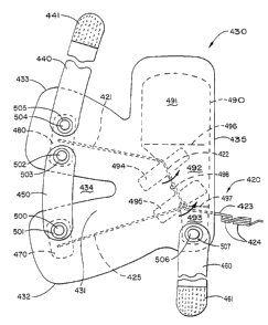
FIG. 14 shows a plan view of the forearm component
of the preferred embodiment of the dynamic splint
illustrated in FIGS . 12 and 13 with its maj or topologic al
features .
FIG. 15 shows a sectional view of the splint and
forearm taken from F IG. 12, illustrating how the dorsal
block is employed in the preferred embodiment .
It is to be understood that the present invention is
not limited in its application to the details of
construction and arrangement of parts illustrated in the
accompanying drawings, since the invention is capable of
other embodiments, and of being practiced or carried out
in various ways within the scope of the claims . Also, it
is to be understood that the phraseology and terminology
employed herein are for the purpose of description and
not of limitation.
BEST MODES OF CARRYING OUT THE INVENTION
A. Definitions
While several terms have been previously defined
herein within the context of the discussion, the
16
CA 02384683 2002-03-07
WO 01/17467 PCT/US00/24791
terminology to be used in the subsequent detailed
description will now be set forth as an aid for those who
may not be familiar with these terms as used by the
inventor. The terms "volar" and "dorsal" indicate
directions of movement or location, where a volar
movement is in the direction of the palm of the hand and
dorsal movement is in the direction of the back of the
hand. Similarly the terms can indicate position, where,
for example, a volar carpal ligament would be a ligament
located in the carpal complex on the palmar side of the
hand. The terms "proximal" and "distal" relate to the
position of the described object with relationship to the
trunk of the body. Thus, the radius and ulna each has a
proximal end ( the elbow area ) and a distal end ( the wri s t
end) . Similarly the carpus is composed of a proximal
carpal row of five bones and a distal carpal row of five
bones, where the proximal carpal row adj oins the distal
end of the radius and ulna. "Supination" is defined as a
rotational movement of the radius and ulna which results
in a palm up position of the hand, whereas "pronation" i s
defined as a similar rotational movement resulting in a
palm down position of the hand. "Dorsiflexion' is
defined as a movement of the hand which forms an arc by
extending the wrist dorsally. "Cocontraction" is defined
as the interaction between the flexor muscle tendons of
the volar forearm acting on the wrist, fingers and thumb ,
17
CA 02384683 2002-03-07
WO 01/17467 PCT/US00/24791
with the dorsal extensor muscle tendons of the forearm,
to stabilize the same members of the wrist and hand, thus
tending to hold the carpal j oint in a fixed and stable
position.
"Glide" is a term used to describe an involuntary
movement of the carpal metacarpal complex, whereby the
proximal carpal row is said to glide in a shear manner
which maintains a parallel relationship with the distal
forearm. A volar glide is observed when, with the
fingers extended, the palmar plane has moved in a volar
direction with relationship to the distal forearm carpal
joint, such movement consisting of a shear movement in a
volar direction of the proximal carpal row. The
magnitude of volar glide is indicative of the severity of
CTS . Similarly, a dorsal glide is observed when the
dorsal plane of the hand is moved dorsally through a
shear movement of the distal forearm carpal j oint, an
opposite movement of volar glide. "Ulnar deviation" is
defined as a movement of the hand in an ulnar direction
without either dorsal or volar movement; the plane of
ulnar movement is perpendicular to that of dorsal-volar
movement. "Radial deviation" is defined as a movement of
the hand in a radial direction opposite to that of ulnar
deviation.
It has been observed in practice that there is a
change is distance between the metacarpals and the distal
18
CA 02384683 2002-03-07
WO 01/17467 PCT/US00/24791
ulna- radius during flexion and extension of the hand.
This change of distance results in an elliptical path
being followed by the hand during its range of motion
from flexion to extension. Furthermore, a differential
motion has been observed during supination and pronation
between the distal and proximal areas of the forearm. It
is desirable in any dynamic splint design to mirror these
kinematics so that a proper dorsal force can be applied
by the splint appliance to resist volar glide.
B. Initial Embodiment
FIG. 1 illustrates an embodiment for a dynamic
splint appliance for use in the treatment and prevention
of CTS in accordance with the present invent ion,
generally designated by the numeral 10. The sp lint
appliance 10 consists of a forearm component 20, a palmar
component 30, and a biasing component 40 and is shown
configured in FIG. 1 to the right forearm 50 and right
hand 60 of a user with carpal tunnel syndrome. While
subsequent descriptions will for consistency and clarity
be directed towards use of the appliance 10 with the
right forearm of a user, the same appliance can be used
on the left forearm and hand of a user, with all elements
of the appliance being mirror images of those elements
for the right forearm and hand.
19
CA 02384683 2002-03-07
WO 01/17467 PCT/US00/24791
The forearm component 20 is shown more generally in
the plans of FIGS . 1, 2, and 4 . The forearm component 20
is configured as a generally semicircular splint body 100
shown contoured around the dorsal side of the forearm 50
in FIG. 1 and in a flattened plan in FIG. 3. The splint
body 100 is oriented on the forearm 50 with its distal
edge 120 generally covering the distal radius and ulna,
its proximal edge 130 in the direction of the elbow, and
its ulnar edge 110 oriented so that it is generally
parallel to the ulna (not shown) of forearm 50. The
proximal strap support 140 and the transverse strap
fulcrum 160 are wrapped over the dorsum of the forearm 50
so that both extend to points generally adj acent to the
radius bone of the forearm 50, so as to capture only the
dorsum of the forearm 50.
Supination and pronation of the forearm ordinarily
cause the biasing component to bind and the forearm
component to buckle at the dorsum of the forearm. Cutout
150 on the dorsum of splint body 100 is provided to solve
the binding problem. It is generally centered on the
dorsum of the forearm 50 and functions to prevent binding
of the appliance during supination and pronation.
Allowing the distal and proximal ends of splint 100 to
move relatively independently of each other while being
connected only along the ulnar edge 110 provides a two
CA 02384683 2002-03-07
WO 01/17467 PCT/US00/24791
point stabilization of the ulnar edge 110 during
supination and pronation and maintains alignment of the
ulnar edge 110 along the ulnar side of the forearm. The
proximal edge 130 of splint body 100 is convexly
contoured on forearm 50 along the dorsum towards the
distal radial end and away from the proximal radial end
so that the extensor muscle group of the forearm is left
uncovered and ergonomically accommodated without binding .
Splint body 100 consists of a thin metal core
material cut to the shape seen in FIG. 3 and enclosed by
a covering material composed of a neoprene external nylon
or other anti-perspiration material, such material as i s
in common use and knowledge among physical therapists, so
that the splint body 100 can be molded and customized t o
individual forearms and trimmed to accommodate individual
differences in forearm length and circumference . The
exterior of the covering material should is sensitive to
attachment by the hook component of an industry standard
hook-and-loop system of the type sold under the trademark
"VELCRO", so that transverse strap 190 can be removably
attached to appropriate areas of the splint body 100, a s
described below.
Splint body 100 is secured to the forearm 50 by
distal forearm strap 170, proximal forearm strap 180, and
transverse strap 190. Distal forearm strap 170 is secured
21
CA 02384683 2002-03-07
WO 01/17467 PCT/US00/24791
to the splint body 100 by one or more rivets 172, of which
a single representation is shown. The rivet 172 as shown
also serves to prevent the biasing component 4 0 from
significant movement either distally or proximally along
the ulnar side of the forearm. Distal forearm strap 170
is of sufficient length to allow end 174 having an
attached hook and loop fastener strip 177 to be brought
around the ulnar side of the forearm, across the distal
end of the volar forearm, and over the radial forearm,
where end 174 passes through distal buckle 175 and back
onto distal forearm strap 170, where a cooperating hook
and loop fastener strip (not shown) is fixed so that end
174 is removably secured to distal forearm strap 170.
Proximal forearm strap 180 is secured to the
proximal strap support 140 by one or more rivets 182.
Proximal forearm strap 180 is of sufficient length to
allow end 184 having an attached hook and loop fastener
strip 185 to be passed around the radial side of the
forearm, across the proximal end of the volar forearm,
and over the ulnar forearm, where end 184 passes through
proximal buckle 188 and back onto proximal forearm strap
180, where a cooperating hook and loop fastene r strip
(not shown) is fixed so that end 184 is removably secured
to proximal forearm. strap 180. As shown in this
embodiment, proximal buckle 188 is fixedly attached to
22
CA 02384683 2002-03-07
WO 01/17467 PCT/US00/24791
the fixed end 186 of transverse strap 190 which is
fastened to the splint body 100 by rivet 189. However,
two separate straps could be employed and fastened with
separate rivets as required.
Transverse strap 190 is secured to the splint body
100 by rivet 189. As seen from FIGS 1 and 4, transverse
strap 190 follows a line from the proximal ulnar edge o f
the splint body, across the volar forearm, and over the
transverse strap fulcrum 160, where end 192 having a hook
and loop fastener strip 193 is removably secured to the
distal strap 170 at an arbitrary point, either by using a
cooperating hook and loop fastening strip (not shown) or
preferably by attachment directly to the material
comprising the distal strap 170 which is sensitive to
attachment by the hook component of a standard hook-and-
loop fastening means . Transverse strap 190 moves to a
limited extent across the transverse strap fulcrum 160, a
portion of splint body 100 which provides a platform for
transverse strap 190 against the forearm and prevents it
from rubbing or binding during supination and pronation.
Because of a differential rotation between the distal end
and the proximal ends of the forearm during
supination/pronation, the transverse strap 190 tends to
stabilize the splint body 100 by translating this
differential rotation motion to the ulnar edge 110, thus
23
CA 02384683 2002-03-07
WO 01/17467 PCT/US00/24791
maintaining alignment of the ulnar edge 110 with the
ulna .
Referring to FIGS 1, 3, and 5, the biasing component
40 is constructed of a formed wire 200 having a
supporting end 202 and a torquing end 204. The formed
wire 200 is preferably made from a length of 2 4 gauge 3 04
stainless steel with a B2 finish, as is commonly known to
physical therapists in the construction of orthopedic
appliances . A plurality of spring loops 206 are formed
near the torquing end 204 with each comprised of one or
more turns of wire as needed to produce a suitable
tensioning force at the torquing end 204 of approximately
8 pounds . Formed wire 202 is enclosed in the covering
material 208 along the ulnar edge 110 of splint body 100 ,
wherein the proximal end of supporting end 202 is allowed
to rotate freely within the sheath formed by the covering
material as the forearm moves in supination and
pronation. Optionally, rivets (not shown) may be placed
at the proximal end of the splint body 100 at the ulnar
edge 110, wherein the proximal end of the supporting end
202 is captured between the ulnar edge 110 and the rivet
and prevented from migrating within the covering material
away from the ulnar edge 110. An ulnar saddle 210 is
formed in the formed wire 200 and positioned over the
distal ulna 52 to rotationally stabilize the formed wire
24
CA 02384683 2002-03-07
WO 01/17467 PCT/US00/24791
200 during pronation and supination of the forearm. Rivet
172, around which the ulnar saddle 210 is positioned,
serves to stabilize the formed wire 200 from significant
proximal or distal movement . As seen more particularly in
FIG. 5, the ulnar saddle 210 curves from the ulnar side
of the forearm 50 up to a point on the dorsum of the
forearm and then back to the plane of the ulnar edge 110
of splint body 100.
The spring loops 206 are formed and positioned along
formed wire 200 so that they are located laterally on the
ulnar side of the ulnar-radial/metacarpal joint and the
intra-metacarpal joint and are not covered by distal
strap 170. It is believed that each spring to op 206
models the action of the corresponding joint. This
double loop spring arrangement has been found to provide
sufficient proximal-distal tolerance to accommodate
changing distance between the metacarpals and the distal
ulna-radius during flexion and extension of the hand, and
it thus prevents binding of the palmar component 30 when
connected to the torquing end 204. The torquing end 204
of formed wire 200 is shaped so that, when connected with
the palmar component 30 and attached to a hand, the hand
at substantially 20° of dorsiflexion does not encounter
resistance from the biasing component 40.
CA 02384683 2002-03-07
WO 01/17467 PCT/US00/24791
Although the general loop configuration is the
preferred embodiment, other tensioning shapes may be used
to provide resistance to movement of the torquing end of
the biasing component and still remain within the spirit
of the invention, namely, to apply a low force load
oppo sing volar glide over long intervals of time. For
example, during testing of the device, an arrangement was
formulated (not shown) consisting of slotte d bars
comprising the support end and torquing end of the
biasing component, with a coiled spring wound around a
spool, similar to that found in clocks, fixedly connected
to the support end. The torquing end rotated about the
axis of the coiled spring as the end of the coiled spring
applied pressure opposing dorsiflexion. It was found
that this arrangement did not track the change in
distance between the metacarpals and the distal ulna-
radius during flexion and extension of the hand, although
this could be accommodated by fashioning a pin in the
palmar component that would travel along a slot in the
bar comprising the torquing end during flexion . Howeve r,
a rigid bar of such a configuration would interfere with
ulnar and radial deviation during the normal activities
of daily living.
It should be noted that normally the range of
deviation for a hand is approximately 35° in a radial
direction and 45° in an ulnar direction, but much less
26
CA 02384683 2002-03-07
WO 01/17467 PCT/US00/24791
range is required to achieve the activities of daily
living. The biasing component in the form of a shaped
wire 200 allows 20° ulnar deviation, but less restriction
on radial deviation, thus permitting a more natural
movement of the hand.
Referring now to FIGS . 6 and 7, the palmar component
30 is illustrated as having a rigid ulnar gutter 300
enclosing the ulnar side of the hand and serving as a
platform for the fixed attachment of connection block
310. Ulnar gutter 300 is preferably comprised of a
plastic material of any suitable composition to enable it
to be custom fitted and shaped to the individual hand.
Connection block 310 is permanently affixed to ulnar
gutter 300 by any suitable means known to the art,
including rivets, screws, glue, or capture in a molded
channel in ulnar gutter 300. Palm strap 320 is
permanently affixed to the volar end 302 of the ulnar
gutter 300 by means, of a rivet 322, although any suitable
means known to the art can be employed. The volar end
302 of ulnar gutter 300 and the volar end 324 of palm
strap 320 are shaped so that they are substantially
confined between the thenar crease 62 and the MCP joint
crease 64 of a typical hand 60 so as to permit unimpeded
use of, the hand during normal activities of daily living .
Palm strap 320 narrows as it passes over the thenar web
27
CA 02384683 2002-03-07
WO 01/17467 PCT/US00/24791
66 in order to prevent interference with normal
activities . This contouring of palm strap 320 allows
unobstructed flexion of the fingers and opposition
movement of thumb with that of fingers. The dorsal end
326 of palm strap 320 is removably secured to the dorsal
end 304 of the ulnar gutter 300 by cooperating hook and
loop attachment strips 328 attached to the palm strap 320
and ulnar gutter 300 by any suitable means . An alternate
embodiment (not shown) for palm strap 320 would be to
employ the buckling arrangement as described for distal
forearm strap 170, while contouring the shape of the
strap to accommodate the thenar crease, the MCP joint
crease, and the thenar web as described above.
The construction of connection block 310 is given in
FIGS 8, 9, 10, and 11 . Connection block 310 is formed o
f
a rectangular block of material, preferably of metal
composition, having a top side 319 as shown in FIG. 10,
a
receiving end 317 as shown in FIG. 9, and a clamping end
318 as shown in FIG. 10. Receiving end 317 has a
centrally located horizontal bore 311 which is colinear
with the longitudinal axis of connection blo ck 310. An
inclined bore 312 in the same axial plane as the
horizontal bore 311 is slantingly positioned so that at
receiving end 317 inclined bore 312 does not intersect
horizontal bore 311. Incline bore 312 is s1 ant
ingly
28
CA 02384683 2002-03-07
WO 01/17467 PCT/US00/24791
disposed towards the clamping end 318 and horizontal bore
311. Inclined bore 312 gradually approaches horizontal
bore 311 so that it~ intersects horizontal bore 311
forming notch 313, which gradually becomes wider as
inclined bore 312 fully intersects and terminates before
exiting horizontal bore 311 on its opposite si de.
Vertical bore 314 intersecting two opposing faces of
connection block 310 is perpendicular to the axis of both
inclined bore 312 and horizontal bore 311. and is located
at the widest point of notch 313. Vertical bore 314 is
threaded to receive set screw 315. A dado is formed
between the inclined bore 312 and the top side 319 of
connection block 310 . Top side 319 is fixedly j oined to
ulnar gutter 300 with its receiving end 317 oriented
proximally and its clamping end 318 oriented dorsally as
described previously.
During appliance use, the torquing end 204 of formed
wire 200 is inserted into the horizontal bore 3 11 on the
receiving end 317 and made to protrude from the clamping
end 318. The ulnar gutter 300 is positioned and strapped
to the ulnar side of the hand. Set screw 315 is then
tightened against formed wire 200 to force formed wire
200 into notch 313 which clamps the connection block 310
to the formed wire 200, so that connection block 310, and
consequently the ulnar gutter 300 and the ent ire palmar
29
CA 02384683 2002-03-07
WO 01/17467 PCT/US00/24791
component 30, is constrained from rotational movement
about formed wire 200 and from longitudinal motion along
formed wire 200 by the clamping action of notch 313 on
formed wire 200.
This embodiment of the invention has been described
to illustrate one way-in which the theory of the
invention is implemented in a dynamic orthot ic. This
embodiment, while effective in treating CTS, has not
proven to be conducive to mass manufacture, but it has
been presented to show how the problems of preventing
binding during supination and pronation and of providing
a biasing component with the proper characteristics can
be solved without departing from the basic concept of the
invention.
C. Preferred Embodiment
The preferred embodiment of the invention is shown
in FIGS . 12 through 15 . This embodiment has been found
to be more manufacturable than the previous embodiment
and illustrates how the implementation of bias ing
component and the solution to prevent binding of the
biasing component can differ from the first embodiment
and still be within the concept of the invent i on.
Referring to FIGS. 13 and 14 which illustrate in
perspective the ulnar and radial aspect of the orthotic
CA 02384683 2002-03-07
WO 01/17467 PCT/LJS00/24791
as it is worn on the right forearm 50, and to FIG 15
which shows the pattern of the forearm component, the
preferred embodiment of the invention consists of
orthotic 400 which is also composed of a palmar component
410, a biasing component 420, and a forearm component
430. The palmar component 410 is essentially the same as
palmar component 30 described previously.
In describing the forearm component 430 of the
preferred embodiment as shown in FIG. 14, it is
instructive to compare it with the forearm component 20
of the first embodiment as shown in FIG. 3. Both figures
are oriented in the same manner to the right forearm.
The body 431 of the preferred embodiment consists of two
pieces of a substantial external nylon or other anti-
perspiration material, such material as is in common us a
and knowledge among physical therapists, cut to the shape
seen in FIG. 14 and enclosing a core pad of neoprene.
Also enclosed within the two layers of covering material
are several metal portions which shall be described
presently. The covering material should be sensitive to
attachment by the hook component of an industry standard
hook-and-loop system of the type sold under the trademark
"VELCRO" , so that distal buckle 175 and proximal buckle
188 of the previous embodiment can be eliminated and
transverse strap 440 and distal carpal strap 460 can be
31
CA 02384683 2002-03-07
WO 01/17467 PCT/LTS00/24791
removably attached to appropriate areas of splint body
431, as described below.
The ulnar support plate 470, radial support plate
480, and block plate 490 are sandwiched between the two
layers of material composing the splint body 431. Each
plate defines a reinforced area on the orthotic to assist
strap attachment to body 431 and to position and orient
biasing component 420 to the forearm.
Ulnar support plate 470 is positioned on the ulnar
portion 432 of body 431 and radial support plate 480 is
positioned on the radial portion 433 of body 431 and in
opposing relation to ulnar support plate 470. Both are
composed of plastic, dead soft aluminum (a term familiar
to persons knowledgeable in the art ) , or some other
suitable material which is relatively rigid. Dorsal gap
434 separates the ulnar and radial portions of body 431,
with the dorsal strap spanning dorsal gap 434. A first
end of dorsal strap 450 is attached to ulnar support
plate 470 by means of rivet 500 inserted through washer
501, the outer fabric covering of body 431, ulnar support
plate 470, the inner fabric covering of body 431, another
washer (not shown) , and secured in place in the manner o f
rivets . A second end of dorsal strap 450 is attached to
radial support plate 480 in the same manner as the first
end and secured by rivet 502 and washer 503. Dorsal
32
CA 02384683 2002-03-07
WO 01/17467 PCTNS00/24791
strap 450 is positioned on the dorsum of forearm 50 (FIG.
12) . It is composed of the same material as body 431 and
may also contain an expandable portion (not shown) if
desired to allow dorsal strap 450 to expand and contract
during supination and pronation of forearm 50. It serves
to couple the ulnar and radial portions of body 431 to
each other in a manner to allow independent movement of
said portions without binding but maintaining a general
orientation of the portions to forearm 50.
The first end of transverse strap 440 is fixedly
attached to radial support plate 480 by means of rivet
504 and washer 505 in the same manner as described
previously. The second end of transverse strap 440 has a
hook portion 441 sewn thereto and on one side so that it
can be wrapped about the volar forearm and attached to
the surface of the ulnar distal portion of body 431.
Transverse strap 440 corresponds to transverse strap 190
of the first embodiment (FIG. 3) , but passes from the
radial proximal side of the forearm to the distal ulnar
side, rather than from the ulnar proximal side of the
forearm to the distal radial side as shown in FIG. 3.
Like transverse strap 190, transverse strap 440
stabilizes body 431 by translating differential rotation
motion observed in supination and pronation to the radia 1
portion 433 to maintain alignment of radial portion 433
33
CA 02384683 2002-03-07
WO 01/17467 PCT/US00/24791
with the radius of forearm 50. In both cases, transverse
strap 190, 440 loads the supporting end of the biasing
comp onent 40, 420.
Referring again to FIG. 14, block plate 4 90 is
located on the distal edge 435 of splint body 431 and
sandwiched between the two layers of material composing
the splint body 431. It may be composed of a rigid
material which may be appropriately formed, such as
plastic, dead soft aluminum, and the like. Its function
is to provide support for distal carpal strap 460 and to
provide a platform for the biasing component 420. Block
plate 490 is comprised of the following three portions
curved portion 491, horizontal portion 492, and vertical
portion 493. These portions are shown more c1 early in
the cross-sectional view shown in FIG. 15. Vertical
portion 493 forms a ninety degree angle with horizontal
portion 492 at bend 497; curved portion 491 begins its
curvature at bend 496 and continues around the carpus for
an arbitrary distance . Construction of block plate 490
out of dead soft aluminum permits curved portion 491 to
be easily molded to each individual carpus . Horizontal
portion 492 is parallel to the plane 55 defined by the
centers of the ulna and radius of forearm 50. It has
been found by experimentation and measurement that the
ninety degree orientation between portions 493 and 492
34
CA 02384683 2002-03-07
WO 01/17467 PCT/US00/24791
remains invariant over the range of supination and
pronation. Along the angled proximal edge 498 of block
plate 490 are two tabs 494 and 495 to accommodate the
biasing component which shall be presently described.
Tabs 494, 495 are bent back over portion 492 to capture a
section of the biasing component 420 therebetween for
rotational movement of biasing component 420. The first
end of distal carpal strap 460 is fixedly attached to
block plate 490 by means of rivet 506 and washer 507 in
the same manner as previously described for the first end
of the dorsal strap. The second end of distal carpal
strap 460 has a hook portion 461 sewn thereto and on one
side so that it can be wrapped about the carpus and
attached to the surface of the distal portion of body 431
to hold body 431 in close contact and orientation with
the forearm.
The preferred embodiment of the biasing component
420 is illustrated in FIG. 14. It is comprised spring
wire and divided into a torquing end 423, a middle
segment 422, and a support end 421, with middle segment
422 and support end 421 being sandwiched between the two
layers of fabric comprising the splint body 431 and with
torquing end 423 exposed. Torquing end 423 extends from
the within body 431 to attach to the palmar component 410
in the same manner as described previously. Along its
CA 02384683 2002-03-07
WO 01/17467 PCT/US00/24791
extent are two spring loops 424 positioned along the wire
so that they are located laterally on the ulnar side o f
the distal forearm/carpal joint and the carpal/metacarpal
joint and slightly dorsal to the axis of the carpus. The
two spring loops 424 may optionally be enclosed in a
pouch (not shown) composed of the same material
comprising the splint body 431 in order to prevent
chafing of the ulnar side of the hand and to provide a
comfortable pad. Middle segment 422 is loosely captured
by tabs 494, 495 on block plate 491 so that torquing end
423 may swing vertically along portion 493 of block plate
491 without binding. Middle segment 422 is positioned to
rotationally stabilize and maintain the position of the
formed wire comprising the biasing component 420 during
pronation and supination of the forearm. Support end 421
extends along the radial side of forearm 50 so that its
end is captured between radial support plate 480 and the
outer layer of fabric comprising body 431. Support end
421 may be bent slightly from the plane formed by
torquing end 423 and middle segment 422 to better conform
to the radial side of the forearm. To additionally
stabilize the biasing component 420, an ulnar arm 425
formed of spring wire is loosely attached to the wire at
the apex of the angle formed by the torqueing end 423 and
middle segment 422 by means of a simple loop in its end.
36
CA 02384683 2002-03-07
WO 01/17467 PCT/US00/24791
The opposite end of ulnar arm 425 is captured between
ulnar support plate 470 and the outer layer of fabric
comp rising body 431.
The preferred specifications for the biasing
component are as follows . The distance between the
proximal spring loop 424 and the bend between middle
segment 422 and the torqueing end 423 has been found to
be 0 . 65 inches . The obtuse angle between the middle
segment 422 and torquing end 423 should be between 125 °
and 130°, and the angled proximal edge 498 of block plate
490 should therefore mirror this angle. The obtuse angle
between the middle segment 422 and support end 421 should
be between 125° and 135°.
D. Use of the Orthotic
The invention is designed to realisticall y mirror
the movement of the hand without interfering with the
normal activities of daily living . The bias 'ing component
is positioned by the palmar component and the forearm
component to reside laterally on the ulnar side of the
distal forearm/carpal joint and the carpal/metacarpal
joint, and slightly dorsal to the axis of the carpus.
This positioning allows the appliance to correctly trac k
the elliptical path that the hand follows during
extension and flexion. It is adjusted by the therapist
37
CA 02384683 2002-03-07
WO 01/17467 PCT/US00/24791
or at the factory so that force applied by the biasing
component is neutral when the palm is at approximately
20° dorsiflexion. When the palm is moved in a volar
direction, the biasing component tends to force the palm
back to the neutral position at 20° dorsiflexion. This
force is resisted by the extensor muscles of forearm 50
which further tends to strengthen the extensors and
restore a normal four to one flexor to extensor ratio,
which tends to stabilize the carpal-metacarpal joint. At
the same time the dorsal attitude of the palm tends to
apply a long-term low force against the PTCh and over
time will lengthen the ligament and relieve the symptoms
of carpal tunnel syndrome.
In the preferred embodiment, the support end of the
biasing component sets the tension of the dual springs at
the carpus by tightening or loosening the transverse
strap, which loads the springs to the desired tension.
This permits the tension on the biasing component to be
easily adjusted. Furthermore, the design of the biasing
component in the preferred embodiment enables the
orthotic to fit more individuals because it will
accommodate varying sizes of forearm and wrist .
Measurable improvement in the patient' s condition should
be observed in about three to four weeks of continuous
use.
38
CA 02384683 2002-03-07
WO 01/17467 PCT/US00/24791
While only two embodiments have been illustrated and
described, they serve to illustrate obvious modifications
which are contemplated within the scope of this invention
and the following claims . Accordingly, the scope of the
invention should be determined not by the embodiments
illustrated but by the appended claims and their legal
equivalents.
39