Note: Descriptions are shown in the official language in which they were submitted.
CA 02384712 2002-05-03
_ 1 _
88AT BRQ~ANt~BR ~P7~~N~SFLANGB-FOR1~8D PASSAG$~AY
This invention relates to a heat exchanger which is
of the type comprising a plurality of plates disposed in
stacked relationship, with the plates having aligned
inlet openings for a first fluid to be cooled by a second
fluid, aligned outlet openings for the first fluid,
aligned inlet openings for the second fluid, and aligned
outlet openings for the second fluid, the plates being so
formed that between adjacent plates there is a flow
passage, with the alternate flow passages in the stack of
plates permitting flow of the first fluid therethrough
from the first fluid inlet openings to the first fluid
outlet openings but preventing the flow of the second
fluid to these flow passages, and with the remaining
alternate flow passages permitting flow of the second
fluid therethrough from the second fluid inlet openings
to the second fluid outlet openings but preventing the
flow of the first fluid to these remaining flow passages.
One example of such a heat exchanger is that disclosed in
U.S. Patent No. 2,677,531 issued on May 04, 1954 to Hock,
Sr., et al.
It is a primary object of the present invention to
provide a heat exchanger of the above-described type
which is economical to manufacture and which has a high
operating efficiency in that the heat transfer through
the plates forming the flow passages for the first fluid
between the first fluid inlet openings and the first
fluid outlet openings and forming the flow passages for
the second fluid between the second fluid inlet openings
and the second fluid outlet openings is optimised,
thereby achieving a high rate of heat transfer from the
first fluid to the second fluid.
In accordance with the present invention there is
provided a heat exchanger which comprises a plurality of
CA 02384712 2002-05-03
- 2
first fluid core plates, and a plurality of second fluid
core plates. Each plate has a first fluid inlet opening
adjacent one end of the plate, a first fluid outlet
opening spaced from the first fluid inlet opening towards
an opposed end of the plate, a second fluid inlet
opening, and a second fluid outlet opening, with the
second fluid inlet and outlet openings being adjacent
said opposed end of the plate. Each first fluid core
plate has an inwardly inclined, upstanding flange
surrounding the first fluid inlet opening in the plate
except for a portion thereof adjacent said one end of the
plate at which gap means is provided in the flange. The
first fluid outlet opening in the plate extends to
adjacent said opposed end of the plate, and a further
inwardly inclined, upstanding flange surrounds the first
fluid outlet opening in the plate except adjacent said
opposed end of the plate at which gap means is provided
in said further flange. Upstanding bosses in the plate
are disposed on opposite sides of the first fluid outlet
opening in the plate, with the second fluid inlet and
outlet openings being provided in said bosses. Each
second fluid core plate has an upstanding boss with
inwardly inclined side walls with the first fluid inlet
opening being provided in this boss. A further
upstanding boss has the first fluid outlet opening
provided therein with this boss extending to adjacent
said opposed end of the plate, and with said further
upstanding boss having inwardly inclined side walls. The
first fluid core plates and the second fluid core plates
are in alternating stacked relationship, with the
upstanding flange of the first fluid inlet opening of
each first fluid core plate being in sealed nested
contact with the side walls of the boss of the adjacent
second fluid core plate in which the first fluid inlet
opening is provided. Said further upstanding flange
surrounding the first fluid outlet opening of each first
fluid core plate is in sealed nested contact with the
further upstanding boss having the first fluid outlet
CA 02384712 2002-05-03
- 3 -
opening of the adjacent second fluid core plate with a
passageway for flow of the first fluid between said
further upstanding boss of the second fluid core plate on
one side of the first fluid core plate and said further
upstanding boss of the second fluid core plate on the
other side of the first fluid core plate and extending
from the gap means in said further upstanding flange of
the first fluid core plate to the first fluid outlet
opening, and the upstanding bosses in which the second
fluid inlet and outlet openings are provided in each
first fluid core plate being in sealed contact with the
adjacent second fluid core plate. The periphery of each
first fluid core plate is sealed to the periphery of the
adjacent second fluid core plate. Flow passages are
Z5 provided between adjacent ones of the plates, with the
flow passage between each first fluid core plate and the
upwardly adjacent second fluid core plate being a first
fluid flow passage and the flow passage between each
second fluid core plate and the upwardly adjacent first
core plate being a second fluid flow passage, so that the
first fluid flow passages alternate with the second fluid
flow passages, and the first fluid can flow from the
first fluid inlet opening of each first fluid core plate
through the gap means in the associated upstanding
flange, through the first fluid flow passage, and through
the gap means in the further upstanding flange and said
passageway to the first fluid outlet opening, and second
fluid can flow from the second fluid inlet opening of
each second fluid core plate through the second fluid
flow passage to the second fluid outlet opening.
It will be appreciated that alternatively the first
fluid may flow in the reverse direction through the first
fluid flow passage in which case the first fluid outlet
openings in the plates would function as first fluid
inlet openings, and the first fluid inlet openings in the
plates would function as first fluid outlet openings.
CA 02384712 2002-05-03
- 4 -
The first fluid may be oil which could be, for
example, natural or synthetic engine oil, transmission or
power steering oil, with the second fluid being a coolant
for cooling the oil in the heat exchanger, and
hereinafter the first and second fluids are so referred
to. Alternatively, at least one of the first and second
fluids could be, for example, water, deionised water,
heavy water, or refrigerant.
In order that the invention may be more clearly
understood and more readily carried into effect, the same
will now, by way of example, be more fully described with
reference to the accompanying drawings in which:
Fig. 1 is an isometric view of a coolant core plate
of a heat exchanger according to a preferred embodiment
of the invention;
Fig. 2 is an isometric view of an oil core plate of
the heat exchanger according to a preferred embodiment of
the invention;
Fig. 3 is a plan view of the coolant core plate
shown in Fig. 1;
Fig. 4 is a plan view of the oil core plate shown in
Fig. 2;
Fig. 5 is a sectioned view on the line 5-5 in Figs.
3 and 4 of a plurality of the coolant and oil core plates
in stacked relationship;
Fig. 6 is a sectioned view on the line 6-6 in Figs.
3 and 4 of the plurality of coolant and oil core plates
in the stacked relationship;
Fig. 7 is a view corresponding to the circled
portion marked A in Fig. 2 but showing an oil core plate
of the heat exchanger according to an alternative
preferred embodiment of the invention;
Fig. 8 is a sectioned view on the line 8-8 in Fig.
7; and
Fig. 9 is a sectioned view on the line 9-9 in Figs.
3 and 4 of a plurality of the coolant and oil core plates
CA 02384712 2002-05-03
-
plates in stacked relationship, according to a further
preferred embodiment of the invention.
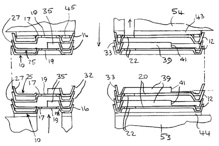
With particular reference to Figs. 1 and 3 of the
drawings, each coolant core plate 10 comprises a planar
5 base 11 which, in the preferred embodiment of the
invention, is surrounded at its periphery by an
upstanding flange 12, this flange 12 being outwardly
inclined in the direction from the base 11. The base 1l
has a coolant inlet opening 13 and a coolant outlet
opening 14 together with, in the preferred embodiment
shown in the drawings, a further opening 15 surrounded by
an upstanding flange 16 which is inwardly inclined in the
direction from the base 11. The base 11 also has an
upstanding boss 17, the side walls 18 of which are
inwardly inclined in the direction from the base 11 and
the upper face of which has an oil inlet opening 19.
Furthermore, the base 11 has a further upstanding boss 20
which is preferably of approximately T-shape, with the
side walls 21 of this boss 20 being inwardly inclined in
the direction from the base 11 and an oil outlet opening
22 being provided in the upper face of the head of the T-
shaped boss 20. The flange 16 surrounding the opening 15
is between and closely spaced from the bosses 17 and 20,
with the coolant inlet opening 13 and the coolant outlet
opening 14 being adjacent an end 23 of the plate 10
opposed to the end 24 thereof adjacent to which the oil
inlet opening 19 is provided and being on opposite sides
of the boss 20 which extends to closely adjacent said
opposed end 23 of the plate 10.
Referring to Figs. 2 and 4, each oil core plate 25
comprises a planar base 26 which, in the preferred
embodiment of the invention, is surrounded at its
periphery by an upstanding flange 27 outwardly inclined
in the direction from the base 26. The base 26 also has
an upstanding boss 28 having a coolant inlet opening 29
in the upper face thereof, together with a further
CA 02384712 2002-05-03
- 6 -
upstanding boss 30 having a coolant outlet opening 31 in
the upper face thereof. An opening 32 surrounded by an
upstanding flange 33 which is inwardly inclined in the
direction from the base 26 is also provided, together
with an oil inlet opening 34 which is surrounded by an
upstanding flange 35 except adjacent the end 36 of the
plate 25 at which a gap 37 is provided in the flange 35,
the flange 35 being inwardly inclined in the direction
from the base 26. The base 26 is furthermore provided
with an oil outlet opening 38 which is of approximately
T-shape and which is surrounded by an upstanding flange
39 except adjacent the opposed end 40 of the plate 25 at
which a gap 41 is provided in the flange 39, the flange
39 being inwardly inclined in the direction from the base
26. The flange 33 surrounding the opening 32 is disposed
between and closely spaced from the flanges 35 and 39.
Each flange 12 and 27 is outwardly inclined in the
direction from the base 11 or 26, respectively, in that
there is an obtuse angle between each flange 12 and 27
and the adjacent portion of the base 11 or 26,
respectively, while the flange 16, the side walls 18 and
the side walls 21 are inwardly inclined in the direction
from the base 11 in that there is an obtuse angle between
the flange 16, the side walls 18, and the side walls 21
and the adjacent portions of the base 11, and each flange
33, 35 and 39 is inwardly inclined in the direction from
the base 26 in that there is an obtuse angle between each
flange 33, 35 and 39 and the adjacent portion of the base
26.
Referring now to Figs. 5 and 6 of the drawings, it
will be noted that in the heat exchanger a plurality of
the coolant core plates 10 and a plurality of the oil
core plates 25 which are of a material or materials, such
as aluminum, stainless steel, or copper alloy, having
high thermal conductivity, are disposed in alternating
stacked relationship, with the flange 35 of each oil core
CA 02384712 2002-05-03
_ 7
plate 25 being in sealed nested contact with the side
walls 18 of the boss 17 of the adjacent coolant core
plate 10, the upstanding flange 39 of each oil core plate
25 being in sealed nested contact with the upstanding
boss 20 of the adjacent coolant core plate 10, the upper
faces of the upstanding bosses 28 and 30 of each oil core
plate 25 being in sealed contact with the adjacent
coolant core plate Z0, the upstanding flange 33 of each
oil core plate 25 being in sealed nested contact with the
outstanding flange 16 of the adjacent coolant core plate
10, and the flange 27 of each oil core plate 25 being in
sealed nested contact with the flange 12 of the adjacent
coolant core plate 10. In alternative embodiments the
flanges 27 of the oil core plates 25 and the flanges 12
of the coolant core plates 10 may be omitted, with the
periphery of the base 26 of each oil core plate 25 being
sealed by other means (not shown) to the periphery of the
base 1l of the adjacent coolant core plate 10. For
example, as shown in Fig. 9 the base 26 of each oil core
plate 25 and the base 11 of each coolant core plate 10
may each have a continuous projecting rib~53 closely
adjacent the periphery of the base 26 and the base 11,
with in each plate 10 the peripheral portion 54 of the
base 11 outside said rib 53 therein being in sealed
contact with the peripheral portion 55 of the base 26
outside said rib 53 therein of an adjacent plate 25 on
one side of said plate 10, said continuous ribs 53 of
these plates 10 and 25 being oppositely directed, and the
continuous rib 53 of each plate 10 being in sealed
contact with the continuous rib 53 of the adjacent plate
25 on the other side of said plate 10.
Preferably, each of the coolant core plates 10 and
the oil core plates 25 are provided with a brazing filler
metal in the form of a cladding, a coating or shim
plates so that, after assembly of the plurality of
coolant core plates 10 and the plurality of oil core
plates 25 as described above, the assembled plates 10, 25
CA 02384712 2002-05-03
may be disposed in a brazing furnace thereby to provide
the above-described sealing of the flange 35 of each oil
core plate 25 to the side walls 18 of the boss 17 of the
adjacent core plate 10, the sealing of the flange 39 of
each oil core plate 25 to the side walls 21 of the boss
20 of the adjacent coolant core plate 10, the sealing of
the flange 33 of each oil core plate 25 to the flange 16
of the adjacent coolant core plate 10, the sealing of the
peripheral flange 27 of each oil core plate 25 to the
peripheral flange 12 of the adjacent coolant core plate
10, and the sealing of the bosses 28 and 30 of each oil
core plate 25 to the adjacent coolant core plate 10.
Ends plates 43 and 44 which are thicker than the
coolant core plates 10 and the oil core plates 25 and
strengthen the assembled heat exchanger are provided,
with these end plates 43, 44 serving to close one end of
the oil inlet openings 34, 19, to close one end of the
oil outlet openings 38, 22, to close one end of the
coolant inlet openings 29, 13, and to close one end of
the coolant outlet openings 31, 14, the upper end plate
43 preferably having thereunder a reinforcement plate 45
which may have corrugations 46 extending between one end
and the opposed end thereof, although alternatively the
corrugations 46 could extend transversely across the
reinforcement plate 45, or in any other direction. The
upper end plate 43 may also be provided with a small
offset hole 47 which is sealingly covered by a flat 48 on
the crest of one of the corrugations of the reinforcement
plate 45 so that it can be externally confirmed by visual
inspection of the assembled heat exchanger that the
reinforcement plate 45 has been installed. A
corresponding flat 48 may be provided on the crest of one
of the corrugations on the opposite face of the
reinforcement plate 45 and in a position such that the
reinforcement plate 45 may be reversed in which case the
small hole 47 is sealingly covered by the flat 48.
CA 02384712 2002-05-03
_ g _
In operation, oil from, for example, an engine block
53 enters the heat exchanger through the oil inlet
openings 19, 34 and flows through the oil flow passage
between the face of the base 26 shown in Fig. 4 and the
adjacent coolant core plate 10 as indicated in chain-
dotted lines in Fig. 4. It will be noted that in order
to enter the oil outlet opening 38 in each oil core plate
25 the oil must flow beyond the lower extremities of the
flange 39 and through the gap 41 in this flange 39
thereby ensuring that the oil flow is over a substantial
portion of the base 26 of each plate 25 and is not
flowing directly from the oil inlet opening 34 to the oil
outlet opening 38, the oil flowing from the heat
exchanger through the oil outlet openings 22, 38 into,
for example, an oil filter 54, the oil outlet openings
22, 38 being positioned to align with the oil inlet to
the filter 54. The oil returns from the filter 54 to the
engine block 53 through the openings 15, 32. Coolant
flows through the coolant inlet openings 13, 29 and flows
through the coolant flow passage between the face of the
base 11 shown in Fig. 3 and the adjacent oil core plate
as indicated in chain-dotted lines in Fig. 3 to the
coolant outlet openings 14, 31. There is thus achieved a
high rate of heat transfer between the oil and the
25 coolant. It will, of course, be appreciated that the
openings 14, 31 could be the coolant inlet openings with
the openings 13, 29 being the coolant outlet openings.
Furthermore, the openings 22, 38 could function as the
oil inlet openings, with the openings 19, 34 functioning
as the oil outlet openings. It will of course also be
appreciated that the side walls 18 of the boss 17, the
side walls 21 of the boss 20 and the flange 16 in each
coolant core plate 10 and the flanges 35, 33 and 39 in
each oil core plate 25 serve as barriers to ensure that
the coolant and oil flows are over a substantial
proportion of the areas of the bases 11 of the coolant
core plates l0 and the bases 26 of the oil core plates
25. In one or more of the coolant core plates 10 the end
CA 02384712 2002-05-03
- 10 -
of the T-shaped boss 20 remote from the head thereof may
be spaced a greater distance from the end 23 of the plate
to permit, if desired, a portion of the coolant to
bypass directly from the coolant inlet opening 13 to the
5 coolant outlet opening 14.
It will be appreciated that the height of each oil
flow passage and the height of each coolant flow passage
is dependent on the extent of the nesting of the
alternate coolant core plates 10 and oil core plates 25,
10 and hence is dependent on the angle of inclination of the
flange 16 and of the side walls 18 and 21 of the bosses
17 and 20, respectively, of each coolant core plate 10
and on the angle of inclination of the flanges 35, 33 and
39 and the height of the bosses 28 and 30 of each oil
core plate 25, and in relation to the preferred
embodiments of the :invention shown in the drawings, on
the angle of inclination of the flange 12 of each coolant
core plate 10 and the angle of inclination of the flange
27 of each oil core plate 25.
Turbulisers which may be of conventional form, such
as the turbulisers 60 of U.S. Patent No. 6,244,334 issued
on June 12, 2001 to Wu, et al., and assigned to the
applicant in the present application, are preferably
disposed in one or more of the oil flow passages and may
also be disposed in one or more of the coolant flow
passages, these tur:bulisers serving to disrupt the oil or
coolant flow in each of the oil or coolant flow passages
in which they are installed and to disturb the boundary
layers of the oil or coolant flow at the surfaces of the
plates, thereby improving the efficiency of heat transfer
from the oil to the coolant in the heat exchanger. For
clarity, these turbulisers are shown only in Figs. 3 and
4 and only in outline denoted by broken lines 42. The
turbulisers 42 have a high pressure drop (HPD) flow
direction in which maximum turbulising of the oil flow
occurs but with a high pressure drop in the oil flow, and
CA 02384712 2002-05-03
- 11 -
a transverse low pressure drop (LPD) flow direction in
which there is reduced turbulising of the oil flow but
with low pressure drop in the oil flow. As desired, the
turbulisers 52 may each be disposed in either the HPD or
LPD flow direction. Instead of using these turbulisers
42, the base 11 of one or more of the coolant core plates
may be formed with spaced, protruding dimples 49 a few
of which are shown in Fig. 1, and the base 26 of one or
more of the oil core plates 25 may be formed with spaced,
10 protruding ribs 50 a few of which are shown in Fig. 2,
the dimples 49 and the ribs 50 serving the same purpose
as the turbulisers 42. While the dimples 49 are shown on
the base 11 of the coolant core plates 10 and the ribs 50
are shown on the base 26 of the oil core plates 25 it
will be appreciated that alternatively the dimples 49
could be on the base 26 of one or more of the oil core
plates 25 with the ribs 50 on the base 11 of one or more
of the coolant core plates 10, or dimples 49 could be on
the base 11 of one or more of the coolant core plates 10
and also on the base 26 of one or more of the oil core
plates 25, or ribs 50 could be on the base 26 of one or
more of the oil core plates 25 and also on the base 11 of
one or more of the coolant core plates 10. Furthermore,
the base 1I of one or more of the coolant core plates 10
and the base 26 of one or more of the oil core plates 25
could each be formed with the dimples 49 and the ribs 50,
and in adjacent coolant and oil core plates 10 and 25 the
bases 11 and 26 thereof may be formed with the dimples 49
and/or the ribs 50 with the dimples 49 and/or the ribs 50
of one of these bases 11 and 26 being brazed to the
dimples 49 and/or the ribs 50 of the other of these bases
11 and 26. This increases the structural strength of the
assembled heat exchanger, as does the provision of the
turbulisers 42, each of which is brazed to the adjacent
plates 10 and 25.
Referring to Figs. 7 and 8, it will be noted that in
the alternative preferred embodiment shown therein the
CA 02384712 2002-05-03
- 12 -
gap 41 is replaced by two gaps 41' each of which is
provided by a pair of cuts 51 such as lanced cuts in the
flange 39, with the portion of the flange 39 between each
pair of cuts 51 being inwardly bent and cut off at 52,
the inwardly turned Zips at 52 providing increased
contact with the boss 20 of the coolant core plate 10
which is in contact therewith. The gap 37 in the flange
35 may likewise be formed by a pair of cuts in the flange
35, with the portion of the flange 35 between these cuts
being inwardly bent and cut off, and with the inwardly
turned lip at the cut off providing increased contact
with the boss 17 of the coolant core plate 10 which is in
contact therewith.
The length of the gaps 41', and the length of the
gap 41 in the preferred embodiment hereinbefore described
with reference to Figs. 1 to 6, inclusive, may be varied
to optimize the heat transfer in relation to the pressure
drop and oil flow characteristics.