Note: Descriptions are shown in the official language in which they were submitted.
CA 02384831 2008-06-02
1
APPARATUS AND METHOD FOR DETECTION OF FOREIGN BODIES IN
PRODUCTS
Technical field
The present invention relates to an apparatus for detection of foreign bodies
in products, especially in food products. The invention also relates to a
method using said apparatus.
Further more the present invention relates to an apparatus for detection of
changes in material properties and contents in a product, especially
detection of voids, defects and inhomogeneities within a material. The
invention also relates to a method using said apparatus.
Background of the invention
Intensive efforts to improve product quality are presently undertaken within
the food industry, such as reducing the probability of products containing
foreign bodies to reach the consumer market.
The term foreign bodies comprises all solid materials that are undesired in
food products, originating from the product or not, such as bone fragments,
bits of glass, rubber, grovel/stone, hair, insects, etc. Present techniques to
detect some classes of foreign bodies in food products are very expensive
and/or can only detect some foreign bodies, such as magnetic bodies, bodies
with deviating colour and size or bodies with deviating weight. Examples of
such techniques are ocular examination and X-ray detection.
In the Japanese Patent JP 63285487, by Shigeru, a detection method of
metal in foodstuff is disclosed. The purpose of the invention is to detect
metal powder, irrespective of the shape and size of the foodstuff by
irradiating metal contaminated foodstuff with microwaves in order to
generate an electric discharge, which discharge is detected.
CA 02384831 2008-06-02
2
In WO 96/21153, by Hoskens et al., an apparatus for determining the
qualities of an irradiatable body by means of penetrating radiation is
disclosed, where said radiation could be of any wavelength. The apparatus
comprises a device for parallel radiation from one side of a irradiable body,
a
device for receiving the radiation leaving the body and deriving a
transmission signal therefrom, and means for deriving from the transmission
signal information concerning the qualities of the irradiated body, such as
bone tissue in pieces of meat.
From information derived from the transmission signal the mass of the
inspected body is determined, the mass of the body is a function of height
and density and a correlation exists between mass and radiation
attenuation, thus a presence of possible inhomogeneities may be detected.
A problem encountered with the prior art is that it is impossible, or very
difficult, to detect a multitude of different types of foreign bodies in
products.
Metal or particles with high density are easy to detect in a product
containing material with low density, but foreign bodies embedded in a
material with a similar density are difficult to detect.
A further problem with present techniques is that it is difficult to achieve
on-
line detection of foreign bodies on a completed product in production, which
means that the detecting method has to be fast, non-invasive and non-
destructive.
Summary of the invention
A first object with the invention is to provide an apparatus and a method for
detection of foreign bodies in products, especially food products, which
overcome the above mentioned problems.
The first object is achieved by an apparatus for detection of foreign bodies
in
a product comprising: a first antenna device for transmitting electromagnetic
signals in the microwave range, the signals comprise at least two signals at
CA 02384831 2008-06-02
3
different frequencies fi-f5; a second antenna device for receiving signals
originating from the first antenna, the received signals, at least partially,
have passed through the product.
Each signal comprises amplitude and phase information and the apparatus
further comprises: a gap between the first and second antenna in an open
structure, whereby a production line may be placed in the gap so that the
product is transported through the gap in a direction x; and means for
measuring at least the amplitude and phase information of the received
signals for each separate frequency fi-f5, so as to obtain parameter values
for
each movement of the product in the direction x.
The apparatus also comprises means for comparing each parameter value
with the corresponding amplitude and phase information of the transmitted
signals, so as to obtain a comparison value for each movement of the
product in the direction x and for each of the separate frequencies fi-f5;
means for analyzing each comparison value based on a reference value,
which reference value is accessible to the apparatus; and means for emitting
a signal when the comparison value differs a predetermined amount from
said reference value.
Further the first object is achieved by a method for detection of foreign
bodies in a product comprising: transmitting electromagnetic signals from a
first antenna device, the transmitted electromagnetic signals being in the
microwave range, the signals comprise at least two signals at different
frequencies fl-f5, receiving signals in a second antenna device originating
from the signals transmitted from the first antenna device, where the
received signals, at least partially, have passed through the product.
The method further comprises the steps of: transporting the product through
a gap between the first and second antenna in a direction x, storing
reference values, comprising amplitude and phase information, for each
transmitted different frequency in a memory, measuring at least amplitude
and phase information of the received signals for each separate frequency fl -
CA 02384831 2008-06-02
3a
fs, so as to obtain parameter values for each movement of the product in the
direction x.
The parameter values are then compared with the corresponding amplitude
and phase information of the transmitted signals, so as to obtain a
comparison value for each movement of the product in the direction x for
each of the frequencies f1-f5. Each comparison value is thereafter analyzed
using one of the reference values from the memory, and emitting a signal
when the comparison value differs a predetermined amount from the
reference value.
A second object with the invention is to provide an apparatus and a method
for detection of changes in material property and content in materials.
The second object is achieved by an apparatus for detection of changes in
material properties and contents in a product, comprising: a first antenna
device for transmitting electromagnetic signals in the microwave range, the
signals comprise at least two signals at different frequencies fi-f5; a second
antenna device for receiving signals originating from the first antenna, the
received signals, at least partially, have passed through the product.
Each signal comprises amplitude and phase information and the apparatus
further comprises: a gap between the first and second antenna in an open
structure, whereby a production line may be placed in the gap so that the
product is transported through the gap in a direction x; and means for
measuring at least the amplitude and phase information of the received
signals for each separate frequency fl-fs, so as to obtain parameter values
for
each movement in the direction x.
The apparatus also comprises means for comparing each parameter value
with the corresponding amplitude and phase information of the transmitted
signals, so as to obtain a comparison value for each movement in the
direction x and for each of the separate frequencies fl-f5; means for
analyzing
each comparison value based on a reference value, which reference value is
CA 02384831 2008-06-02
3b
accessible to the apparatus; and means for emitting a signal when the
comparison value differs a predetermined amount from the reference value.
Further the second object is achieved by a method for detection of changes
in material properties and contents in a product comprising the steps of:
transmitting electromagnetic signals from a first antenna device, said
transmitted electromagnetic signals being in the microwave range, said
signals comprise at least two signals at different frequencies f1-f5; and
receiving signals in a second antenna device originating from said signals
transmitted from said first antenna device, where said received signals, at
least partially, have passed through said product.
The method further comprises the steps of: transporting said product
through a gap between said first and second antenna in a direction x; storing
reference values, comprising amplitude and phase information, for each
transmitted different frequency in a memory; and measuring at least
amplitude and phase information of said received signals for each separate
frequency fi-fs, so as to obtain parameter values for each movement of the
product in said direction x.
The parameter values are then compared with the corresponding amplitude
and phase information of said transmitted signals, so as to obtain a
comparison value for each movement of the product and for each of said
frequencies fl-f5. Each comparison value is thereafter analyzed using one of
said reference values from said memory, and a signal is emitted when said
comparison value differs a predetermined amount from said reference value.
An advantage with the present invention is that a large variety of foreign
bodies is detectable in a product.
Another advantage is that the present invention allows fast measurement,
detection and evaluation.
CA 02384831 2008-06-02
3c
Still another advantage is that the present invention is cheap and easy to
implement and can be integrated in existing production facilities.
CA 02384831 2002-03-13
WO 01/20311 PCT/SEOO/01783
4
Still another advantage is that the present invention allows
to detect foreign bodies in products after final processing,
in a non-destructive manner.
Yet another advantage is that the invention provides an
apparatus and a method for detecting deviation of the material
properties and contents of a product, or material, provided
that the product comprises two components having different
dielectric constants.
Brief description of the drawings
Fig. 1 shows an apparatus according to the present invention.
Fig. 2 shows an antenna device, which may be used in the
apparatus in Fig. 1.
Fig. 3 shows a side view of an antenna arrangement according
to the present invention.
Fig. 4 shows a side view of an antenna arrangement, as in
figure 2, illustrating diffraction/scattering in an examined
product.
Fig. 5a-Sc shows a method to extract information regarding
diffraction measurements, according to the present invention.
Detailed description of preferred embodiments
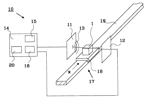
Figure 1 shows an apparatus 10 for detection of foreign bodies
in a product 1 according to the present invention. The
inventive apparatus comprises a first antenna device 11, a
second antenna device 12, where said first antenna device 11
transmits electromagnetic signals 13' in the microwave range.
The transmitted signals 13' are arranged to, at least
partially, pass through the product 1, which is under
CA 02384831 2002-03-13
WO 01/20311 PCT/SEOO/01783
examination. After the signals have passed through the
material 1 the signals 13" are received at said second antenna
device 12.
The first and second antenna device 11, 12 transmits and
5 receives signals having at least two separate frequencies,
preferably more, e.g. 400, different separate frequencies in
several contiguous frequency blocks furthermore referred to as
frequency channels. The antenna devices, which are described
in more detail in figure 2, are connected to a microwave
circuit 14, such as a network analyser. The microwave circuit
14 comprises a microwave oscillator 15, which feeds signals
13' to be transmitted to the first antenna device 11, and a
microwave measuring system 16, e.g. a vector voltmeter, which
collects and measure certain parameters, such as amplitude JA1
and/or phase cp, of the received signals 13" from the second
antenna device 12.
The product 1 which is under examination is preferably placed
on a transportation system 17 comprising, for instance, a
carrier 18 on a conveying equipment 19, a conveyor belt, a
vertical pipe with flowing products or the like.
In the described preferred embodiment, the products pass
through a gap between the first 11 and the second 12 antenna
device, to allow the transmitted signals to, at least
partially, pass through the whole of said product. The product
1, which is placed on the carrier 18, is moved through the
open space by means of, for instance, a motor driven cart.
Signals having pre-selected number of frequencies in the
microwave range, in one or more frequency channels, are
transmitted from said first antenna device, and are received
at said second antenna device to be measured in the network
CA 02384831 2002-03-13
WO 01/20311 PCT/SEOO/01783
6
analyser 14. A new measurement is performed after a
predetermined time interval, during which the product has
moved a distance in a first direction x.
The antenna devices comprise at least one frequency channel
within which channel at least two separate frequencies may be
transmitted. This may be implemented using a separate antenna
,or antenna section, for each frequency channel, where the
frequency of each transmitted signal within each frequency
channel may be controlled by the microwave oscillator 15.
A preferred embodiment of a first antenna device 11 is shown
in figure 2, which transmits signals in a plurality of
frequency channels, fl-f6. This type of antenna is a patch
antenna with capacitively coupled patches. The mid frequency
for each frequency channel could be as presented in table 1.
This type of patch antenna is cheap to manufacture and simple
to control to achieve the desired number of channels, each
channel being controllable to contain at least two signals
with separate frequencies. The second antenna device 12
comprises the same features as the first antenna device 11 for
reception of the transmitted signals.
CA 02384831 2002-03-13
WO 01/20311 PCT/SEOO/01783
7
Channel Frequency [GHz]
fl 1.45
fz 3.2
f3 4.1
f4 4.5
f5 5.2
f6 5.8
Table 1: A schematic layout of the wave pattern of the centre
frequencies is illustrated in figure 2 as dashed lines with
reference to the different channels f1-f6 in table 1.
By using this type of antenna device 11, in the above
described apparatus 10, information containing the dielectric
function can be obtained in an examined product as a function
of said first direction x, and said selected frequencies.
It is essential to have at least two signals with separate
frequencies within at least one frequency channel to reach the
above mentioned information regarding the dielectric constant,
according to the invention. This will come more apparent in
the following.
The basic theory behind the invention is to detect
differences, such as foreign bodies, contamination, damages
(cracks etc.), causing a change in the dielectric constant of
the examined product. This is done by transmitting signals, at
least partially, through said product, which in it self must,
at least partially, consist of a dielectric substance.
Parameter values from said parameters, such as amplitude JAI
and/or phase cp, which are used for determining the dielectric
constant of the examined product, are measured in said
microwave measuring system 16. The measured parameter values
CA 02384831 2002-03-13
WO 01/20311 PCT/SE00/01783
8
are compared with the corresponding values of the transmitted
signals, so as to obtain a comparison value for each frequency
in each frequency channel.
Each comparison value is then compared with a reference value,
which is available to the microwave circuit 14, e.g. stored in
a memory 20 in said microwave circuit 14. Reference values are
preferably obtained by measuring parameters from received
signals that have passed through a reference sample of the
examined type of product, which reference sample is free from
any foreign bodies or other defects that will cause a change
of the properties of the microwave transmission through the
product as described by the profile of the dielectric function
as a function of frequency.
Sometimes it is difficult to obtain a "clean" reference sample
and, therefore, the reference values are preferably obtained
by measuring parameter values of a plurality of products, and
calculate statistics, such as an average, for each parameter
value and use that as a reference value for each frequency. A
typical number of products, measured to obtain said calculated
reference value, is approximately 100 products.
Alternatively reference values may be obtained evaluating a
model for the microwave transmission through the product and
the transmit and receive properties of the antennas 11 and 12.
Figure 3 shows a side view of the measurement gap where the
examined product 1 passes through. On the left side of the
product is the first antenna device 11 arranged and on the
right side is the second antenna device 12 arranged. A signal
is transmitted from said first antenna device 11, and
received by said second antenna device 12. The received signal
30 as a function of x, s(x), may be expressed by:
CA 02384831 2002-03-13
WO 01/20311 PCT/SEOO/01783
9
s(x) A I ei` ,
where JAI is the amplitude and cp is the phase of the received
signal. The phase cp is proportional to:
(p H kZ=z+27tn,
where z is the distance between the first and the second
antenna device 11, 12, kZ is the propagation constant in the z
direction, and n is an integer number and stands for the
number of completed trains in the gap. The propagation
constant is in turn equal to;
k_ = w su ,
where o) is the angular frequency of the microwave signal
related to the frequency of the microwave signal f by: o=2nf.
s(c,))is the equivalent dielectric function and is the
equivalent permeability of the material in the specific
measurement gap. By transmitting a single signal there is a
possibility to determine the absolute value of the amplitude
and the phase shift of the received signal, but it is
impossible to uniquely determine the equivalent dielectric
function, since phase measurements allow only the
determination of the modulus of the wave trains by 360
degrees. Therefore the integer number of completed wave trains
within the measurement gap is not known from a single
measurement.
In figure 3 there is shown a first transmitted signal 30,
drawn with a continuous line, having two complete oscillation
periods 31, 32, preceding the last not complete period 33. By
adding a second signal 34, drawn with a dashed line, in a
different frequency compared to the first signal 30, having
CA 02384831 2002-03-13
WO 01/20311 PCT/SEOO/01783
two complete oscillation periods 35, 36, preceding the last
not complete period 37, the propagation time may be determined
by plotting the equivalent dielectric function assuming
different number of oscillation periods, as is shown in figure
5 4.
In an examined product, the equivalent dielectric function is
unknown, but may be expressed as a known part, Eproduct (m, ~) ,
belonging to the clean product and an unknown part, Eforeign
body(co,~), belonging to the microwave transmission properties of
10 the foreign body. The equivalent dielectric function of the
foreign body contains scattering, diffraction, absorption,
reflection and transmission effects of the foreign bodies.
Therefore it depends strongly on frequency co (since
diffraction lobes shift with frequency) and with the angle of
observation 4 (if sharp edges are present). The measured
transmitted signal may therefore be broken down in the
following form involving 71, describing the abundancy of
foreign bodies in the product where r1=0 indicates no foreign
body to be present:
Etot = ( 1 -11 ) 'Eproduct + 11 'Eforeign body i ( I )
where 71 varies between 0 and 1, depending on the amount of
foreign bodies present in the examined product.
The amplitude JAI and phase cp of the transmitted microwave
signal S21 is measured for all frequencies and for each
displacement x resulting in a two dimensional graph of a
complex variable (S21=1 A lexp [icp] ), where changes in the products
composition easily can be detected.
CA 02384831 2002-03-13
WO 01/20311 PCT/SEOO/01783
11
Figure 4 illustrates what happens when a signal 13' is
transmitted from said first antenna device 11, through a
product 1. Inside said product, there is a small piece of a
foreign body 60, such as metal, stone, etc., disturbing the
signal on its way to the receiving antenna device 12. The
received signal 13" will in this case be subject to
diffraction or scattering causing an interference pattern to
arise. This will mainly be detectable as a characteristic
pattern in the amplitude JAI as a function of displacement and
frequency.
The main task of the signal processing part is the appropriate
filtering of the data and the definition of a threshold value
enabling to discern contaminated from non-contaminated
products minimising the estimator errors in both directions,
i.e. (1) assigning a foreign body to a pure product and (2)
letting a contaminated product pass. Obviously some tolerances
at (1) is given whereas (2) must be reduced as far as
possible. For simple classes of products and foreign bodies
(i.e. homogenous, wet products and dry foreign bodies) it is
sufficient to apply equation (I) directly and replace the
equivalent dielectric function of the pure product by measured
data from a pure product and calculating the difference
between the measured reference and measured product. If the
mean square of the residual does not exceed a certain
threshold, the product is considered ok, otherwise it is
rejected.
Figure 5a-5c illustrates how a useful value may be obtained
using especially the information contained in the diffraction
patterns. Figure 5a shows the damping value IS211 for a specific
displacement x=xl for a multiple of frequencies f, resulting in
a curve 70. By applying a "Fast Fourier Transform" (FFT) on
CA 02384831 2002-03-13
WO 01/20311 PCT/SEOO/01783
12
the damping I S211 a result is obtained, as shown in figure 5b.
This result is subject to suitable filtering techniques to
select a window 71 where the desired information is contained.
These types of filtering techniques are well known to a
skilled person within the technical field and are, thus, not
described in more detail in this application.
Figure 5c shows the resulting curve 73 after a
retransformation of the filtered FFT-spectrum in figure 5b
back to the damping I S21 I (xl) as a function of frequency f. A
threshold value 74 is also indicated, where values lower than
the threshold value for each frequency is allowed, and,
accordingly, values higher than the threshold is unacceptable
and renders an alarm signal from the microwave circuit 14,
where the FFT treatment is performed.
The above described apparatus and method for detecting foreign
bodies in material, may also be used within the area of
monitoring and detecting changes in material property and
content, provided said material comprises at least two
different components having different dielectric constants. An
example of such a material is a material having a void within
the material, such as a plastic part having an air bubble
inside. These types of defects are easily detected by using
the inventive apparatus and method.