Note: Descriptions are shown in the official language in which they were submitted.
CA 02384950 2002-05-03
a
ADHESIVE FOR ATTACHING BUTTRESS MATERIAL
TO A SURGICAL FASTENING DEVICE
FIELD OF THE INVENTION
The present invention relates, in general, to surgical fastening devices for
applying a plurality of surgical fasteners into tissue and, more particularly,
to a novel
method of attaching a buttress material onto the surgical fastening device for
the
purpose of creating a reinforced surgical fastener line within tissue.
BACKGROUND OF THE INVENTION
Many surgical procedures involve the resection of tissue. One such procedure
is lung volume reduction, which resects a portion of lung to treat emphysema.
One
problem encountered during the resection of body tissue, especially in
conjunction with
the use of staples, is the issue of hemostasis. Certain types of body tissue
are more
prone to the hemostasis issue such as the thin friable tissue found in the
lung, and
disease conditions can exacerbate the problems. Mechanical devices such as
surgical
staplers and linear cutters, both open and endoscopic, are utilized as a means
of
resecting diseased lung tissue. Staples provide hemostasis in vascular
structures, and
when applied to lung tissue, provide a good degree of pneumostasis as well.
Surgical
stapling instruments have a plurality of staples held in multiple staggered
rows in a
replaceable cartridge and a pair of opposed jaws of which at least one is
moveable.
The surgical stapling instruments compress the lung tissue between the
cartridge and
the jaw, and the staples are fired into the compressed tissue in close
proximity to the
diseased portion of the lung that is to be excised. A cutting blade is passed
longitudinally between the innermost rows of formed staples, transecting the
tissue.
The surgical stapling device is removed from the surgical site, reloaded with
another
unfired stapling cartridge, and the procedure is repeated until the desired
section of the
lung is resected and removed. An example of an open linear cutter is given in
U.S.
Patent 5,415,334 assigned to Ethicon Endo-Surgery, Cincinnati, Ohio on May 16,
1995, which is hereby incorporated herein by reference. An example of an
endoscopic
CA 02384950 2002-05-03
linear cutter is given in U.S. Patent 5,597,107 assigned to Ethicon Endo-
Surgery
Cincinnati, Ohio on January 28, 1997, which is hereby incorporated herein by
reference.
One known problem with using surgical staplers used in this fashion has been
the formation of air leaks in the stapled lung tissue. The leaks can occur in
the cut
Iine, and/or in the staple holes themselves. Frequently, the diseased lung
tissue is thin
and friable and can tear at the staples as the lungs re-inflate. These air
leaks can be
persistent and can extend the hospital stay for a patient by weeks. As a means
to
alleviate these leakage problems, surgeons reinforce the staple line by
applying a
buttress or pledget material to the desired stapling site and stapling through
the buttress
material. The buttress material provides reinforcement to the friable tissue.
The tissue
is compressed against the staple holes resulting in increased pneumostasis.
This
reduces the chances of tissue tearing at the staple line, and reduces staple
pullout in
friable tissue.
These reinforcement materials are typically releasably mounted onto the jaw
members of a surgical stapling device such that upon firing, the reinforcement
material
is stapled to the lung tissue. Optimally the lung tissue is "sandwiched"
between two
layers of this reinforcement material. Alternately, buttress materials can be
used in a
number of other surgical procedures such as but not limited to; an ovarian
hysterectomy, a gastric bypass, an anastomosis of intestinal tissue, or any
other
procedure that can require the reinforcement of a staple tine or increased
hemostasis in
tissue.
Releasably attaching the buttress material to the jaw members of the surgical
stapling device presents a special challenge. The buttress material must be
fastened
securely to the jaws of the surgical stapling device so that it won't fall off
during
normal operation, yet must be easily released from the surgical stapling
device after the
staples are fired. A variety of adhesive and mechanical attachment means are
known.
Both adhesive and mechanical attachments means are discussed below, and both
have
their deficiencies.
z
CA 02384950 2002-05-03
r
One example of a device which attaches a buttress material to a linear cutter
with an adhesive is described in U.S. Patent No. 5,441,193 and by Gravener et
al.
This device attaches buttress materials to a surgical instrument with a
biocompatible
cyanoacrylate adhesive. The adhesive bonding is applied along the edge
portions of the
buttress material and dashed lines of perforations are placed within the
buttress
material (adjacent to the glue line) so that the unglued central portion of
buttress
material can be torn from the glued edge portions. However, the portions of
the
buttress material having the adhesive applied thereto are is not releasable
from the
device. As a consequence, removing the buttress from the instrument (after
firing) can
be especially difficult, as all of the material between the perforations must
be torn
simultaneously to release the surgical stapling device from tissue.
What is needed was an adhesive that would releasably attach the buttress
material to the surgical device in a manner that makes it easier for the
surgeon to
remove the surgical device from the surgical site after firing. U.S. Patent
No.
5,752,965 by Francis et al. teaches the attaching the buttress material or
strips to a
surgical stapling device with a releasable adhesive that must be applied just
prior to
use. An alignment fixture is used to align the pair of buttress strips,
adhesive is
applied to the exposed surface of each buttress strip, and the jaws of the
surgical
stapling device are then closed upon the adhesive and buttress strips. When
the jaws
are opened, the buttress material is attached to the jaw and the cartridge of
the surgical
stapling device with the tacky liquid adhesive. The tacky liquid adhesive is
taught as
being composed of hydroxypropylmethyl cellulose, polypropylene glycol, and
water.
While attaching a buttress material in this manner may offer a releasable
adhesive, the
adhesive effects of the tacky liquid adhesive are temporary. In addition, the
attachment
process is time consuming, and the attachment step must be repeated for each
firing.
Lastly, once the tacky adhesive is exposed to air, volatile elements of the
adhesive
begin to evaporate. This limits the application of this tacky adhesive to just
prior to or
during surgery.
3
CA 02384950 2002-05-03
What is needed is a releasable adhesive that that won't dry out or degrade
over
time. Such an adhesive would enable the buttress material to be attached to
the
surgical stapling device at the manufacturing plant, and would result in both
time and
cost savings. European patent application EP 1064883A1 by Leslie Hamilton et
al.
teaches a releasable adhesive of nontoxic bioabsorbable aliphatic ester
polymers that
are semi-crystalline solids or tacky liquids (of honey-like consistency). The
adhesive is
characterized by being flowable at body temperatures (37° C) and
preferably flowable
at room temperatures (25° C). However, the adhesive may become much
more fluid at
the elevated temperatures (up to 50° C) frequently encountered in
trucks, shipping
containers, railroad cars, and warehouses. Under the elevated temperature
conditions,
the adhesive can migrate to other parts of the instrument or instrument
packaging and
the migration can reduce the strength of the adhesive bond.
As seen from the above discussion, attaching a buttress material to a surgical
stapler with an adhesive can present many problems. Mechanical attachment of
buttress material to a surgical stapling device is also well known in the art
and avoids
the issues found with adhesives. Many methods of mechanical attachment exist,
and a
common one is the placement of a sleeve over the clamping members of the
surgical
stapling device. The sleeves can be formed from flexible fabric such as
buttress
material, or can contain a releasable strip of buttress material attached to a
different
fabric. Many of these sleeves are described in U.S. Patent No. 5,503,638 by
Cooper
et al, in U.S. Patent No. 5,702,409 by Rayburn et al., in U.S. Patent No.
5,810,855
by Rayburn et al., and in U.S. Patent 5,964,774 by McKean et al.
While sleeves can effectively be used to attach the buttress material to the
end
effector of the surgical stapling device, sleeves can cause other
complications during
surgery. For example, if the sleeve is formed from a solid sleeve of buttress
material,
firing the surgical stapling device staples the buttress and tissue and severs
the buttress
sleeve and tissue between the staple lines. This action leaves the portions of
tissue (on
either side of the cut line) attached together by a sheet of buttress
material. This
requires the surgeon to go in and sever the cut sleeve of buttress to separate
the severed
tissue, and remove any unwanted portion of the buttress material. .
4
CA 02384950 2002-05-03
What is needed is a means of releasably attaching a buttress strip onto a
surgical
stapling device, that remains effective over a long period of time, remains
operational
at all temperatures that are likely to be encountered by the product, and is
easily
released from the surgical stapling device.
SUn~MARY OF THE INVENTION
In accordance with the present invention, there is provided a surgical
stapling
instrument for clamping and stapling tissue. The instrument has a handle and
first and
a second opposed tissue clamping members connected to the handle. The members
are
movable between an open position for receiving tissue therebetween and a
closed
position for stapling tissue therebetween. At least one of the first and
second clamping
members houses a plurality of staples. The device also includes a strip of
buttress
material releasably attached to at least one of the first and second tissue
clamping
members by a hot melt adhesive. The buttress material disposed on the clamping
member such that the staples can attach the buttress material to tissue
between the
clamping members.
Also in accordance with the present invention, there is provided a staple
cartridge for attachment to an end effector of a surgical stapling instrument.
The
cartridge includes a member housing a plurality of staples. The member
includes a
device for releasably attaching itself to a surgical instrument. The cartridge
further
includes a strip of buttress material releasably attached to the member by a
hot melt
adhesive.
Also in accordance with the present invention, there is provided a method for
releasing buttress material from a stapling instrument when the buttress is
attached to
the instrument by an adhesive. The method includes providing stapling
instrument
comprising first and a second opposed tissue clamping members movable between
an
open position, for receiving tissue therebetween, and a closed position for
stapling
tissue therebetween. At least one of the first and second clamping members
houses a
5
CA 02384950 2002-05-03
plurality of staples, and a .strip of buttress material is releasably attached
to the first
tissue clamping member by an adhesive. The method then involves moving the
instrument to its open position and inserting tissue between the clamping
members.
Thereafter, the method involves releasing the buttress material from
attachment to the
first clamping member by closing the instrument and stapling the buttress
material to
the tissue. Whereby the movement of the staples breaks the adhesive bond and
releases
the buttress material from the first clamping member.
BRIEF DESCRIPTION OF THE DRAWINGS
The novel features of the invention are set forth with particularity in the
appended claims. The invention itself, however, both as to organization and
methods
of operation, together with further objects and advantages thereof, may best
be
understood by reference to the following description, taken in conjunction
with the
accompanying drawings in which:
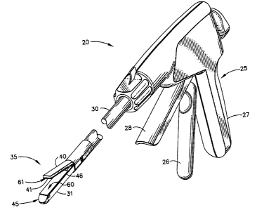
FIG. 1 is an isometric view of a surgical stapling device showing an end
effector having buttress strips releasably attached to a first clamping
surface of an anvil
and releasably attached to a second clamping surface of a staple cartridge by
a hot melt
adhesive of the present invention;
FIG. 2 is an enlarged isometric view of the end effector of the surgical
stapling
device of FIG. 1 with the anvil sectioned and rotated for clarity, the view
showing the
step of applying the molten hot melt adhesive of the present invention onto
the first and
second clamping surfaces of the end effector with an applicator;
FIG. 3 is an enlarged isometric view of the end effector of the surgical
stapling
device with the anvil sectioned and rotated for clarity, the view showing the
step of
attaching a strip of buttress material onto each of the tissue clamping
surfaces by
placing the buttress material into contact with molten hot melt adhesive of
the present
invention placed thereon;
6
CA 02384950 2002-05-03
FIG. 4 is an isometric exploded view of the step ~ of cooling the hot melt
adhesive of the present invention past a set point, the releasable adhesive
becoming a
solid and adhering each of the portions of buttress material to each of the
respective
tissue clamping surfaces;
FIG. 5 is an isometric view of a circular stapling instrument showing buttress
rings placed thereon prior to the step of applying the molten adhesive of the
present
invention onto an anvil and staple cartridge of the circular stapling
instrument for the
attachment of the buttress rings thereto;
FIG. 6 is an isometric view of a surgical stapling device showing an end
effector having buttress strips releasably attached to a first clamping
surface of an anvil
by an anvil carrier, the buttress strip being removable by distal motion
relative to the
surgical stapling device;
FIG. 7 is an isometric exploded view of the elements of the anvil carrier
showing the path of a perforated buttress strip as it is releasably assembled
with a
carrier shell;
FIG. 7;
carrier;
FIG. 8 is an isometric view of the assembled elements of the anvil carrier of
FIG. 9 is a distal end view of an alternate assembly of the elements of the
anvil
FIG. 10 is an isometric exploded view of an alternate embodiment of a
removable carrier shell and the perforated buttress strip; and
FIG. 11 is an isometric view of a circular stapling instrument with an anvil
in
the open position and an attachment ring attached to the anvil, wherein a
perforated
buttress ring is being removably and rotatably attached onto the attachment
ring.
7
CA 02384950 2002-05-03
DETAILED DESCRIPTION OF THE INVENTION
Referring now to the figures in which like numerals indicate the same element
throughout the views, FIG. 1 shows a surgical stapling device 20 made in
accordance
with the present invention. Device 20 has an end effector 35 with a first
buttress strip
60 and a second buttress strip 61 attached thereon with a hot melt adhesive of
the
present invention. The surgical stapling device 20 shown is an endocutter and
is well
known in the art for clamping, stapling, and cutting body tissue. Alternately,
the
surgical stapling device 20 can be one of a number of other fastening devices
such as a
circular stapler, a stapler, a clip applier, or any one of a number of other
fastening or
stapling devices capable of single or multiple firings. The staples or
fasteners can be
contained within a staple cartridge formed integrally with the surgical
stapling device,
or within a removable staple cartridge that can be fired and replaced allowing
multiple
firings from the same surgical fastening device.
Surgical stapling device 20 has a handle 25 for the operator to grasp, an
elongated shaft 30 extending distally from the handle 25, and end effector 35
extending
distally from the shaft 30. End effector 35 has a first and a second tissue
clamping
member movable between an open position for receiving tissue therebetween, and
a
closed position for stapling tissue therebetween. The first tissue clamping
member has
a fixed channel 31 extending from the shaft 30 and a removable staple
cartridge 45
mounted therein. The second tissue clamping member is a moveable anvil 40
which is
opposite to the second tissue clamping member. Staple cartridge 45 is shown
placed
within the fixed channel 31 and contains a plurality of staples 49 housed
within.
Moveable anvil 40 is operably attached to a closure trigger 26 extending from
the
handle 25 and moves in response to movement of the closure trigger 26. Moving
the
closure trigger 26 from the open position shown in FIG. 1 towards a grip 27 of
the
handle 25 moves the anvil 40 from the open position of FIG. 1 to a closed
position
adjacent to the removable staple cartridge 45 (not shown). Movement of a
firing
trigger 28 towards the closure trigger 26 (when closure nigger 26 and anvil 40
are in
the closed position) expels the plurality of staples 49 contained within the
removable
8
CA 02384950 2002-05-03
staple cartridge 45. The staples 49 are driven from the removable staple
cartridge 45,
through the buttress strips 60 and 61, and are formed into tight "B" shapes
(not
shown) against the anvil 40. An example of the surgical stapling device 20 is
the
TSB35 Endopath~" ETS Endoscopic Linear Cutter by Ethicon-Endo Surgery, 4545
Creek Road, Cincinnati, OH. The surgical stapling device 20 arid removable
staple
cartridge 45 are generally described in a commonly assigned U.S. Patent No.
5,597,107, which is incorporated herein by reference.
As shown in FIG. 1, the first and a second buttress strip 60 and 61 are
releasably attached to a first tissue clamping surface 46 of the removable
staple
cartridge 45 and a second clamping surface 41 of the anvil 40. The buttress
strips 60
and 61 can be formed from a wide variety of buttress materials including
VICRYL ~,
produced by Ethicon, Inc., Somerville New Jersey, "DEXON ~, produced by
Sherwood-Davis and Geck, St. Louis, Missouri, and TEFLON ~, produced by E. I.
DuPont de Nemours & Co., Wilmington, Delaware. Additionally, other materials
include animal material such as tanned bovine pericardium, biocompatable
elastomers
such as E-caprolactone glycolide produced by Ethicon Inc., Gargrave, England,
or any
one of a number of suitable buttress materials. Suitable s-caprolactone
glycolide
materials or foams are of special interest and are described in U.S. Patent
No.
5,468,253 hereby incorporated by reference. It is an object of the present
invention to
releasably attach the buttress strips 60 and 61 to at least a portion the
surgical stapling
device 20 for long periods of time, up to two or more years.
ATTACHMENT OF BUTTRESS STRIPS WITH A HOT MELT ADHESIVE
FIGS. 2-4 shows the steps of releasably attaching buttress strips 60 and 61 to
the first and second tissue clamping surfaces 46,41 of the end effector 35
respectively,
with a solid adhesive 65 of the present invention. Solid adhesive 65 is a
solid at room
temperatures (25° C), a solid at body temperatures (37°), and
meltable at elevated
temperatures. Adhesives of this type are called hot melt adhesives, and are
applied as
a molten adhesive 66 during the gluing process.
9
CA 02384950 2002-05-03
When the molten adhesive 66 cools, it reverts back into the solid adhesive 65,
forming an adhesive bond. In FIGS. 2-4, the end effector 35 of the surgical
stapling
device 20 is shown enlarged, and the anvil 40 is shown sectioned and rotated
for
clarity.
FIG. 2 shows the first step of applying the molten adhesive 66 to the first
and
second clamping surfaces 46,41 with an applicator 70. The applicator 70 has a
handle
72, a distal nozzle 71 for the disbursement of molten adhesive 66, a resistive
heating
device 75 contained within the handle 72 to melt the a distal end of the solid
adhesive
65, an applicator trigger 73, and an electrical cord 74. Attachment of the
electrical
cord 74 to a power supply 80 engages the resistive heating device 75. Handle
72 has
cooling slots 77 adjacent to the resistive heating device 75 to prevent
overheating.
These types of glue or adhesive applicators 70 are well known in the art as
hot melt
glue guns and are readily available for commercial or home use. An excellent
example
of a hot melt glue gun or adhesive applicator 70 is the SHURE BONDER~ Pro 9000
glue gun made by FPL Corporation, Wauconda, IL, 60084.
In FIG. 2, a rod of solid adhesive 65 is shown inserted into an opening at the
proximal end of the handle 72. As the rod of solid adhesive 65 is inserted, it
operably
engages a feeding mechanism (not shown) that is operably coupled to the
applicator
trigger 73. Actuation of the applicator trigger 73 moves the rod of solid
adhesive 65
distally within the handle until it contacts the hot resistive heating device
75 and melts
the distal portion of the rod of solid adhesive 65. Applying additional
pressure on the
applicator trigger 73 forces the molten adhesive 66 from an orifice 76 of the
nozzle 71
and moves the rod of solid adhesive 65 distally into the applicator 70.
Whereas the hot
melt glue gun or applicator 70 is the preferred method of applying the solid
adhesive
65, alternate adhesive appliers are available. These alternate adhesive
appliers include
but are not limited to a pressurized molten glue dispenser that applies a
molten ribbon
of adhesive, a sprayer that applies a spray of molten droplets, and a hot
roller that
applies a film of molten adhesive.
CA 02384950 2002-05-03
In FIG. 2, the applicator 70 is shown applying several lines of molten
adhesive
66 onto the first and second tissue clamlSing surfaces 46,41 of the anvil 40
and
cartridge 45. The molten adhesive is applied to these surfaces prior to the
step of
applying the buttress strips 60 and 61. The molten adhesive 66 is shown being
applied
onto the second tissue clamping surface 41 between the staple pockets 42
embossed
therein. The two lines of molten adhesive 66 are kept short on the second
tissue
clamping surface 41 and provide enough retention force to attach the first
buttress strip
60 onto the second tissue clamping surface 41, yet enable the first buttress
strip 60 to
be easily removed.
Two longer rows of molten adhesive 66 are shown placed upon the first
clamping surface 46 of the removable staple cartridge 45, between longitudinal
rows of
staple slots 47. Each staple slot 47 has a piston-like staple driver 48 (not
shown)
moveable from a first recessed position deep within the removable staple
cartridge 45
to a second position extending from the first tissue clamping surface 46. In
FIGS. 2
and 3, the staple drivers 48 are in the first recessed position deep within
the staple slots
47 of the removable staple camidge 45. A "U" shaped staple 49 (not shown) is
placed
within each staple slot 47, on top of the staple drivers 48 recessed therein.
Movement
of the staple drivers 48 to the second position ejects the staples 49 from the
removable
cartridge 45. In these FIGS., the staple drivers 48 and staples 49 are
recessed within
the staple slots 47 and cannot be seen. Staple cartridges 45 and movement of
the
staple drivers 48 and staples 49 are well known in the art and can be found in
U.S.
Patent 5,415,334 by Williamson, IV et al., which is incorporated herein by
reference.
As shown in FIG. 3, once the molten adhesive 66 is applied, the second step is
to apply the buttress strips 60 and 61 onto their respective tissue clamping
surfaces
46,41. The first and second buttress strips 60 and 61 are shown moving towards
the
first and second tissue clamping surfaces 46,41 and the molten adhesive 66.
FIG. 4
shows the last step of the gluing process where the buttress strips 60 and 61
are placed
into position, and pressed onto the respective clamping surfaces 46,41. As the
buttress
strips 60, 61 are pressed into place, the molten adhesive 66 is compressed
between the
11
CA 02384950 2002-05-03
buttress strips 61 and the clamping surfaces 46,41, and allowed to cool back
into the
solid adhesive 65, attaching the buttress 60,61 to the surgical stapling
device 20.
Firing the surgical stapling device 20 moves the staple drivers 48 from the
first
position within the camidge 45 to the second position i.e. extended from the
first tissue
clamping surface 46. This action simultaneously lifts and forms the staples 49
against
the anvil 40 and lifts the first buttress strip 60 upwardly and away from the
first tissue
clamping surface 46 of the cartridge 45. The upwards movement of the first
buttress
strip 60 breaks the adhesive bond between the first buttress strip 60 and the
first tissue
clamping surface 46, releasing the first buttress strip 61 from the staple
cartridge 45.
Alternately, the buttress strip 61 can be adhered to the cartridge 45 by
generally
placing the molten adhesive 66 into the staple slots 47 and attaching the
first buttress
strip 60 onto the camidge 45. The molten adhesive can be placed into the
staple slots
47 in two different ways. First, the hot melt can be injected directly into
the staple
slots 47 with the hot melt glue gun, adhering the buttress strip 60 to the
staple slot 47
(not shown). Second, the molten adhesive 66 can enter the staple pockets 48 by
placing the molten adhesive 66 onto the first tissue clamping surface 46
adjacent to the
staple slot 47 (FIG. 3), and forcing it into the staple pockets 48 by pressing
the first
buttress strip 60 against the first clamping surface 46. The act of pressing
forces most
of the molten adhesive 66 from the first tissue clamping surface 46 and into
the
adjacent staple slots 47, adhering the buttress 61 to both the staple slots 47
and the first
tissue clamping surface 46 (not shown). When solid adhesive 65 is within the
staple
slots 47 and the surgical stapling device 20 is fired, the staple drivers 48
and staples 49
move upwardly within the staple slots 47 and contact the solid adhesive 65
therein.
The contact with the moving staple drivers 48 and staples 49 ejects the solid
adhesive
65 from the slots 47 and breaks the adhesive bond between the first buttress
strip 60
and the removable staple cartridge 45.
Thus, the solid adhesive 65 of the present invention becomes a releasable
adhesive when the firing of the surgical stapling instrument 20 is used to
break the
adhesive bond between the staple cartridge 45 and the first buttress strip 60.
It is
12
CA 02384950 2002-05-03
important to note that using the firing of the stapling device 20 to break an
adhesive
bond is not dependent on the adhesive composition. That is, a wide variety of
adhesives can be released in the manners described above. In addition to hot
melt
adhesives, other adhesives can be applied at room temperatures and can include
adhesives such as elastomeric compounds, RTV silicones, natural and synthetic
rubbers, anaerobic compounds, sealants, moldable compounds such as dental dam
compounds, or maleable materials such as waxes. Additionally, the above
adhesives or
any one of a number of other adhesives such as acrylics, cyanoacrylates,
epoxies and
the like can be used with a bonding inhibitor. The bonding inhibitors act as a
barrier
to reduce the strength of the adhesive bond and can include oils, greases,
waxes, mold
releases, Teflon's, silicones or any other surface contaminant that inhibits
the adhesive
bonding strength.
The ejection of the staples 49 from the removable staple cartridge 45 also
releases the second buttress strip 61 from the second tissue clamping surface
41 and
forms the "U" shaped staples 49 into "B" shapes. The "U" shaped staples 49 are
formed into "B" shapes by driving them through the second buttress strip 62
attached
to the second tissue clamping surface 41 and against the staple pockets 42
within the
anvil 40. As the wire of the staple 49 is driven into the staple pocket 42,
the ends of
the staple wire curl around into the "B" shape, and dislodge the solid
adhesive 65 from
the staple pockets 42 and the second tissue clamping surface 41. This action
detaches
the second buttress strip 61 from the anvil 40 (not shown).
FIG. 5 shows molten adhesive 66 being used to attach buttress materials to a
circular stapler 85. Buttress rings 86 are shown exploded away from a first
and a
second circular compression surfaces 88,87 just prior to the step of gluing
the buttress
rings 86 onto the circular compression surfaces 88,87 with molten adhesive 66.
THE HOT MELT ADHESIVE COMPOSITION
The solid adhesive 65 can be any one of a variety of hot melt adhesives that
are
commercially available. It is preferable that the hot melt adhesive be
biocompatible
with body tissue and can be natural or manmade. Natural biological polymers,
and in
13
CA 02384950 2002-05-03
particular a number of biological proteins can be used as hot melt adhesives.
These
proteins can include collagen, gelatin, fibrin, fibronectin, fibrinogen,
elastin, serum
albumin, hemoglobin, ovalbumin and the like or any combination thereof.
Additionally, polysaccharides such as hyaluronic acid, chondroitin sulfate,
hydroxyethyl starch, hydroxyethyl cellulose, hydroxypropyl-cellulose,
carboxyetyl-
cellulose, chitan/chitosan, agarose and alginate may be used alone or in
combination
with other materials.
Manmade materials can include poly (lactic acid), poly (glycolic acid) poly
(hydroxybutyrate), poly (phosphazine), polyester, polyethylene glycol,
polyethylene
oxide, polyacrylamide, polyhydroxyethylmethylacrylate, poly-vinypyrrolidon,
polyvinyl alcohol, polyacrylic acid, polyacetate, polycaprolactone,
polypropelene,
nylon and the like.
Of special interest for the solid adhesive 65 is a copolymer that is a solid
at
temperatures generally below 40° C. The preferred copolymer is a
copolymer of s-
caprolactone or trimethylene carbonate and glycolide. Most preferably, the
copolymer
is a copolymer of s-caprolactone and glycolide. The amount of s-caprolactone
can be
between 30 and 45 weight percent with the balance being glycolide. Ideally,
the
copolymer can be composed of 36:64 (mol/mol) [poly(E-caprolactone-co-
glycolide)].
The copolymer is an elastomeric containing less than one percent of unreacted
monomer as determined by proton NMR spectography. The inherent viscosity is
determined in a 0.1 gldL solution of hexaflouroisopropanol (HFIP) at
25° C, and can
range from about 0.8 g/dL to about 3.2 g/dL, preferably from about 0.8 g/dL to
about
2.4 g/dL, and- most preferably at about 1.6 g/dL. In an especially preferred
embodiment, both the preferred solid adhesive and the preferred buttress
material can
be formed from the same bioabsorbable material, s-caprolactone glycolide.
The solid adhesive 65 can be characterized as being a solid at temperatures up
to 40° C. and melts without degradation at elevated temperatures
between 40.1 ° C to
600° C. More preferred are solid adhesives 65 that melt without
degradation at
14
CA 02384950 2002-05-03
elevated temperatures between 120° C to 240° C and most
preferably at 180° C. The
copolymer described above can be prepared in accordance with the descriptions
provided in U.S. Patents Nos. 5,468,253, 5,133,739, and 4,605,730, each of
which is
incorporated by reference.
ALTERNATE DEVICE AND METHOD FOR ATTACHING
BUTTRESS STRIPS TO AN ANVIL
FIGS. 6-10 illustrate another device and method for attaching a buttress strip
onto an anvil 40 of the surgical stapling device 20 of FIG. 1. FIG. 6 shows
the
surgical stapling device 20 with an anvil carrier 90 secured to the anvil 40,
and a
buttress strip removably attached to the anvil carrier 90. Anvil carrier 90
slides onto
the anvil 40 and locks onto the anvil 40 when fully mounted. The lock can be
easily
disengaged for removal or replacement of the anvil carrier 90.
As best shown in FIGS. 7-9, the anvil carrier 90 is assembled fram a frame or
carrier shell 91 and a perforated buttress strip 100. Carrier shell 91 is
hollow, is
conformed to slip over the anvil 40, has an inverted "U" shaped carrier body
92, and
has a nose 95 extending distally therefrom. Nose 95 can be blunt or atraumatic
to
prevent tissue damage during placement of the surgical stapling device 20 at
the
surgical site. A spring member 96 connects nose 95 to a distal end of the
carrier body
92. A lock or retention feature 97 is located on an inner surface (not shown)
of the
nose 95 to releasably engage the anvil carrier 90 with the anvil 40 of the
surgical
stapling device 20. The retention feature 97 can be a convex dimple or rib
that
engages with a concave mating feature (not shown) on the anvil 40. of the
surgical
stapling device 20. Lifting the nose 95 away from the anvil 40 (when the
retention
feature 97 is engaged with the anvil 40) deflects the spring member 96, lifts
the
retention feature 97 from the concave mating feature on the anvil 40, and
unlocks the
carrier shell from the anvil 40. A plurality of attachment features, such as "
L"
shaped hooks 93, extend downwardly on each side of the carrier body 92, with
arms 94
extending horizontally in the distal direction from a vertical portion or
first member
93a of the "L" shaped hooks 93. Whereas hooks 93 are the preferred embodiment,
CA 02384950 2002-05-03
spikes, arms, tabs, bosses or any one of a number of releasable means can be
added to
the carrier shell 91. Carrier shell 91 can be made from a rigid or semi- rigid
material
such as an engineering plastic, examples of which can include liquid crystal
polymers,
polycarbonates, polystyrenes, or any one of a number of suitable medical
grades of
engineering thermoform plastics or thermoset plastics. Additionally, the
carrier shell
91 can also be formed from any metallic material such as aluminum, steel,
stainless
steel, copper, or combinations and alloys thereof.
Perforated buttress strip 100 is a rectangular sheet formed from any of the
buttress materials described above, and has rows of spaced-apart openings 101
extending therethrough. Perforated buttress strip 100 is attached onto the
carrier shell
91 by threading each horizontal arm 94 fully into each respective opening 101
within
the perforated buttress strip 100 until the openings 101 are brought into
contact with
the first member 93a or vertical portion of the "L" shaped hooks 93. Moving
the
perforated buttress strip 100 distally relative to the carrier shell 91, moves
the openings
101 off of the arms 94 and releases the perforated buttress strip 100 from the
carrier
shell 91. Thus, the perforated buttress strip 100 is detachable from the
carrier shell 91
by linear motion in one direction. Arrows are provided in FIG. 7 to show the
path of
the openings 101 as the perforated buttress strip 100 is threaded onto the
arms 94.
FIG. 8 is an isometric view showing the preferred assembly of the perforated
buttress strip 100 with the carrier shell 91. In this assembly, each of the
arms 94 of
the hooks 93 are shown placed into their respective openings 100 within
perforated
buttress strip 100. When the arms 94 are assembled with the openings 101, a
slight
dimpling occurs at the edges of the perforated buttress 100 from the placement
of the
arms 94 into the openings 101. When the preferred assembly of the anvil
carrier 90 is
installed onto the anvil 40, the perforated buttress strip 100 is tented away
from the
carrier shell 91 by the second clamping surface 41 of the anvil 40, flattening
the
perforated buttress strip 100.
FIG. 9 is a cross sectional view of an alternate assembly of the perforated
buttress strip 100 with the carrier shell 91. In this FIG., the edges of the
perforated
16
CA 02384950 2002-05-03
buttress strip 100 are folded upwardly along each row of openings 101 into a
general
"U" shape. The vertical sides of the "U" shaped perforated buttress 101 are
then
placed inside of the hooks 93, and each of the arms 94 are threaded into their
respective openings 101. This attachment method produces a generally flat
horizontal
section on the attached perforated buttress strip 100.
During surgery, the anvil carrier 90 is used in the following manner. The
anvil
carrier 90 (containing a perforated buttress strip 100) is slid onto the open
anvil 40 of
the surgical stapling device 20. Next, the anvil 40 is closed and the end
effector 35 of
the surgical stapling device 20 is inserted into the patient. The anvil 40 is
opened and
the end effector is placed onto tissue at a selected surgical site. Anvil 40
is closed to
clamp tissue between a second clamping surface 41 on the anvil 40 and a first
clamping
surface 46 on the removable staple cartridge 45. The surgical stapling device
20 is
fired, stapling the perforated buttress strip 100 onto tissue and severing the
tissue and
buttress between the staple lines. The anvil 40 is opened, and the surgical
stapling
device 20 is withdrawn proximally away from the surgical site. As the surgical
stapling device 20 is withdrawn, the stapled perforated buttress strip 100
remains
attached to tissue and the arms 94 of the carrier shell 91 slip out of the
openings 101
within the perforated buttress strip 100, releasing the perforated buttress
strip 100 from
the surgical stapling device 20. To reload the surgical stapling device 20
with a fresh
anvil carrier 90, the surgeon must remove the surgical stapling device 20 from
the
patient. Next, the surgeon removes the spent carrier shell 91 from the anvil
40 by
lifting the nose 95 to unlock the retention feature 97 from the anvil 40 and
slides the
carrier shell 91 off of the anvil 40. A fresh anvil carrier 90 is slid onto
the anvil 40 to
finish the reloading process.
Fig. 10 shows an alternate embodiment of a removable carrier shell 191 that
can be simultaneously detached from both the anvil 40 and perforated buttress
strip
100, releasing the perforated buttress strip 100 from the surgical stapling
device 20 in
the process. Removable carrier shell 191and has elongated carrier body 192,
hooks
193 with arms 194 and first member 193a extending therefrom and a nose 195. A
tang 198 extends from the proximal end of the carrier shell 191, and has a
long suture
17
CA 02384950 2002-05-03
or cable 199 fixedly attached to the tang 116. Perforated buttress strip 100
can be
assembled with the removable carrier shell 115 in either manner described
previously
and shown in FIGS. 8 and 9.
During surgery, removable carrier shell 191 having perforated buttress strip
100 attached thereto are slid onto the anvil 40 of the end effector 35. Cable
199 is
then extended proximally from the removable carrier shell I91 along the shaft
30, and
terminated with a free end adjacent to the handle 25 of the surgical stapling
instrument
20. Placement of the end effector 35 into a patient (through a trocar) leaves
the free
end of the cable 199 outside of the patient's body. After clamping the end
effector 35
on tissue and firing the surgical stapling device 20, the perforated buttress
strip 100 is
released from the surgical stapling device 20 by pulling on the cable 199.
Pulling on
the cable 199 simultaneously moves the removable carrier shell 191 distally
and
detaches it from the anvil 40. As the removable carrier shell 191 moves
distally, the
arms 194 are withdrawn from the openings 101 within the perforated buttress
strip 101
releasing the perforated buttress strip 100 from the removable carrier shell
191 and the
anvil 40. Opening the anvil 40 releases the perforated buttress strip 100 and
attached
tissue from the end effector 35. The cable 199 is then used to withdraw the
spent
removable carrier shell 115 from the patient through the trocar.
.
FIG. 11 shows yet another embodiment of removably attaching perforated
buttress to a stapling device, a circular stapler 85. In this embodiment, the
buttress is
released from the circular stapling device by a rotary motion, rather than the
linear
motion described previously. As shown, the circular- stapler 85 has an open
circular
anvil 89 and a longitudinal axis. An attachment ring 105 is attached to or
formed
from the circular anvil 89. Tab hooks 106 extend distally from the attachment
ring 105
towards the body of the instrument and have tab arms 106a. Tab arms 106a
extend
from the tab hooks 106 in the same counter clockwise direction around the
periphery of
the circular anvil 89. The tab hooks 106 are spaced radially outwardly so that
the so
that circular anvil 85 can fully close without crushing the tab hooks 106.
18
CA 02384950 2002-05-03
A perforated buttress ring 107 is provided to attach to the tab hooks 106
extending from the circular anvil 89. A plurality of tabs 108 are spaced about
the
periphery of the perforated buttress ring 107, with a tab opening 109
extending through
each tab 108. As shown, there are four tabs 108 equally spaced about the
periphery of
the perforated buttress ring 107 and a like number of tab hooks 106. To
removably
attach the perforated buttress ring 107 to the tab hooks 106 of attachment
ring 105, the
tab openings 109 are placed onto the tab arms 106a and the perforated buttress
ring 107
is rotated clockwise. Likewise, counterclockwise rotation removes an attached
perforated buttress ring 107. Alternately, the tab arms 106a can extend in a
clockwise
direction, in which case the perforated buttress ring 107 is rotated
counterclockwise to
install and clockwise to remove. After stapling the perforated buttress ring
107 onto
tissue, the circular anvil 89 is opened and the circular stapler 85 is rotated
clockwise to
withdraw the arms 94 from the tab openings and releasing the perforated
buttress ring
107 from the circular stapler 85. Since the circular stapler 85 is a single
shot
instrument, the attachment ring 105 can be permanently or removably attached
to the
circular anvil 89. Alternately, a perforated buttress ring 107 can be attached
over the
first circular compression surface 88 by attaching a second attachment ring
105
adjacent to the first circular compression surface 88 with the tab hooks 106
extending
distally (not shown). If attachment rings 105 are attached adjacent to both
the first and
second circular compression surfaces 88,87, care must be taken to orient both
sets of
attachment ring hooks 94 to prevent contact during closure, and the arms 94 on
both
attachment rings 105 in the same direction (not shown). With the arms 94
oriented in
the same direction, rotating the circular stapler 85 detaches both perforated
buttress
rings 107 simultaneously.
Although particular embodiments of the present invention have been shown and
described, modification may be made to the device and/or method without
departing
from the spirit and scope of the present invention. The terms used in
describing the
invention are used in their descriptive sense and not as terms of limitations.
19