Note: Descriptions are shown in the official language in which they were submitted.
CA 02384959 2002-03-13
1
1 DEVICE AND METHOD FOR WAVELENGTH-DEPENDENT LIGHT
2 OUTCOUPLING
3
4
The invention relates to an exposure apparatus comprising a lamp and a
6 condensor device, in particular for wavelength-dependent light outcoupling,
7 whereby a first, wavelength-dependent mirror layer is located within the
exposure
8 beam path to divide the beam path into a first, UV portion for exposure, and
into
9 a second, primarily visible and/or IR spectral portion, whereby a second
mirror is
located in the beam path of the second spectral portion that reflects the
second
11 spectral portion back to the first mirror layer.
12
13 Such an exposure apparatus for photocopiers is made known in US 4,095,881.
14 The light from a halogen lamp strikes a curved reflector, from which point
a
parallel bundle of rays is partially reflected by an interference filter
located in front
16 of the lamp in the beam path, and its IR portion is allowed to pass
through. The
17 IR portion is reflected back into the lamp via a mirror, in order to warm
it up and
18 thereby save electrical energy to operate the lamp.
19
An exposure method is made known in JP-A-3022518 in which a wavelength-
21 selective mirror layer that divides the beam path into a spectral portion
used for
22 exposure and into a further spectral portion is penetrated by radiation
within the
23 exposure beam path of a lamp. Under normal circumstances, the further
spectral
24 portion is focussed on the end of a bundle of light guides that is
connected to a
device for controlling the correct focussing. The disadvantage of this method
is
26 the fact that the entire spectral portion not used for exposure causes the
27 instrument parts radiated by it to heat up considerably. This can lead to
the
28 maladjustment or even destruction of the instrument parts.
29
The object of the invention is to propose an exposure apparatus and a method
31 with which exposure quality can be optimized using simple means.
AMENDED PAGE
I PEA/EP
CA 02384959 2002-03-13
2
1 This object is attained by means of the invention by the fact that a viewing
screen
2 is located in the beam path of the light portion of the second spectrai
portion
3 reflected on the first mirror layer before the second pass through this
first mirror
4 layer, and by the fact that imaging optics are located between the viewing
screen
and the first mirror layer to image the lamp on the viewing screen.
6
7 Light is outcoupled in wavelength-dependent fashion with the aid of the
first,
8 preferably wavelength-dependent mirror layer. The light emitted from the
lamp is
9 thereby divided into a UV portion used for exposure, and into an unused,
visible
and IR spectral portion. The used UV spectral portion is diverted in the
direction
11 toward the lens, while the visible and the IR portion pass through the
mirror layer.
12 By optimizing the mirror layer, reflection coefficients of nearly R=100%
and
13 transmission coefficients of T=90% can be achieved. By using a plurality of
such
14 units, a suppression of greater than 1:1000 can be achieved with a utilized
light
efficiency of approximately 98%. Due to light outcoupling, the UV portion is
16 practically all that reaches the offset printing plate for exposure. The
energy in
17 the undesired spectral range that is received is very low. No unnecessary
heating
18 up-or the negative consequences related thereto-takes place.
19
The first, visible and IR spectral portion-which is not used for exposure and
21 passes through the first, wavelength-dependent mirror layer-is reflected on
the
22 second mirror located, in particular, perpendicular to the propagation of
the
23 unused spectral portion, back in the direction of the first mirror layer.
Exactly like
24 the first pass, this second pass through the first mirror layer is not
complete,
either, because residual reflectance remains. A portion, A=T*(1-T), is
reflected on
26 the mirror layer and diverted in a direction away from the object and
toward a
27 viewing screen, on which an image of the lamp is then created by means of
28 imaging optics. This image is used to adjust the lamp. This allows for a
much
29 more effective positioning of the lamp than could be achieved using an
unadjusted installation, due to the mechanical tolerances of lamps. The result
is
31 a much more accurate illumination of the object to be illuminated.
Appropriate
AMENDED PAGE
IPEA/EP
CA 02384959 2002-03-13
3
1 reference marks can be applied on the viewing screen to simplify the
adjustment
2 process.
3
4 The largest share of the second spectral portion, which is not used for
exposure,
passes through the mirror layer back in the direction of the lamp, i.e., it
does not
6 reach the offset printing plate. The radiant energy can be absorbed here by
lamp
7 cooling elements already in place. No further elements are needed to absorb
the
8 portion not used for exposure. As a result, the entire apparatus can be
designed
9 to be more compact and, in particular, more cost-effective.
11 An image of the lamp, the lamp filament, or the lamp electrodes is created
on the
12 viewing screen. The exposure apparatus can now be adjusted effectively
using
13 this image. The viewing screen preferably comprises a ground-glass screen,
on
14 which a mirror-inverted image of the lamp is projected. This simple
exemplary
embodiment of the viewing screen is cost-effective to manufacture and relates
16 the position of the light source as an image with sufficient accuracy.
17
18 Imaging optics for imaging the lamp on the viewing screen are located
between
19 the viewing screen and the first mirror layer so that an image of the lamp
can be
displayed on the viewing screen. These imaging optics comprise a lens system,
21 for example. The advantage of a lens system is the high light intensity and
good
22 accuracy. By arranging the lenses appropriately, it is possible to create
an
23 enlarged representation of the lamp, which is conducive to a rapid and
simplified
24 adjustment of the exposure apparatus. A simple aperture plate can be used
in
order to reduce installation. According to the principle of a "hidden camera",
this
26 results in a mirror-inverted image of the lamp on the viewing screen, which
is
27 designed as a ground-glass screen, for instance.
28
29 According to an advantageous exemplary embodiment of the invention, the
imaging and reflecting functions of the imaging optics and the mirror can be
31 combined in one component if the second mirror is designed curved in shape.
AMENDED PAGE
IPEA/EP
CA 02384959 2002-03-13
4
1 This design saves costs, because a complicated and cost-intensive lens
system
2 between the mirror wall and viewing screen can be eliminated.
3
4 The exposure apparatus can be further improved if a reflector is located in
the
beam path behind the lamp. It produces a reversed image of the lamp in or,
6 preferably, next to the lamp. The light yield can be nearly doubled as a
result. On
7 the other hand, adjustment can be greatly simplified, because it can now
take
8 place such that the images of the lamp and the lamp image can be positioned
9 side-by-side on the viewing screen.
11 The arrangement of the individual components is extremely important in
order to
12 design the device to be particulary space-saving and efficient. For
example, a
13 condensor and the semipermeable mirror layer are located in the beam path
14 behind the lamp in the ray direction. The semipermeable mirror layer
divides the
light into a first UV portion used for exposure, and into a second spectral
portion,
16 whereby a mirror is located in linear succession after the second spectral
portion,
17 which mirror reflects the second spectral portion back in the direction
toward the
18 semipermeable mirror layer, which is situated so as to divert part of the
second
19 spectral portion to the viewing screen. All functions are therefore
realized in a
very compact design. The light reflected back into the lamp and not used for
21 exposure is absorbed there by cooling elements. Parts of this second
spectral
22 portion serve to adjust the lamp with the aid of the viewing screen. The
fact that
23 only the used UV portion reaches the offset printing plate is particularly
24 advantageous.
26 The object of the method is attained using an exposure method for
wavelength-
27 dependent light outcoupling according to the invention, in which at least a
first,
28 wavelength-dependent mirror layer is penetrated by radiation within an
exposure
29 beam path of a lamp to divide the beam path into a first spectral portion
used for
exposure, and into a second spectral portion, wherein at least one part of the
31 second spectral portion is used to adjust the lamp, wherein the second
spectral
AMENDED PAGE
IPEA/EP
CA 02384959 2008-08-08
25679--56
I portion is reflected on a second mirror back in the direction toward the
first mirror
2 layer, and wherein the light portion reflected in the second pass through
the first
3 mirror layer is imaged on the viewing screen.
4
5 A particularly advantageous aspect of the method is the fact that the lamp
can be
6 easily adjusted by means of the image created, and the largest share of the
7 visible light and, mainly, the IR radiation can be kept away from the
adjusting
8 device. The largest share of the second spectral portion passes through the
9 mirror layer in the second pass through the preferably wavelength-dependent
mirror layer in the direction of the lamp, where the energy is advantageously
11 absorbed by cooling elements already in place. No further cooling elements
are
12 necessary, therefore, which allows for a more compact and cost-effective
design.
13
14 I'he method according to the invention is carried out particularly
advantageously
by the fact that light emitted by a lamp is bundled with the aid of a
condensor and
16 divided by means of a first, wavelength-dependent mirror layer into a
spectral
17 portion used for exposure and into a second spectral portion, whereby the
18 second spectral portion penetrates the mirror layer, is reflected back by a
second
19 mirror in the direction toward the first mirror layer; and is.partially
diverted on the
mirror layer in the direction toward the viewing screen, so that an image of
the
21 lamp is created on the viewing screen. This image is then used to adjust
the
22 lamp. This advantageous exemplary embodiment of the method allows for a
very
23 compact design of the device.
CA 02384959 2008-08-08
25679-56
5a
An aspect of the invention relates to an exposure apparatus,
comprising a lamp; a condenser device; a first wavelength-
dependent mirror layer located within an exposure beam path
of said lamp to divide the beam path into a first UV portion
used for exposure, and into a second spectral portion
selected from the group consisting of a visible portion, an
IR spectral portion, and both; a second mirror located in
the beani path of a second spectral portion that reflects the
second spectral portion back to said first mirror layer; a
viewing screen located in the beam path of a light portion
of said second spectral portion before a second pass through
said first mirror layer; an imaging optics located between
said viewing screen and said first mirror layer to image
said lamp on said viewing screen.
Another aspect of the invention relates to a method for
adjusting a lamp of an exposure apparatus, comprising the
steps of: penetrating at least one first mirror layer by
radiation within an exposure beam path of a lamp to divide
the beam path into a first spectral portion used for
exposure and into a second spectral portion; using at least
one part of the second spectral portion to adjust the lamp;
reflecting the second spectral portion on a second mirror
back in direction toward the first mirror layer; and imaging
the light portion reflected in a second pass through the
first mirror layer, on a viewing screen.
This is described in greater detail using the drawings,
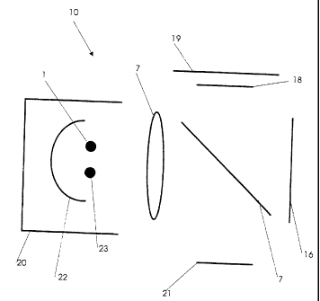
which represent an exemplary embodiment of the invention.
Figure 1 shows a schematic representation of the device
accor_dirig to the invention, and the method, and
CA 02384959 2002-03-13
6
1 Figure 2 shows a schematic representation of the beam path in an exposure
2 apparatus for printing plates using a digital mirror device.
3
4 An exposure apparatus 10 is shown in Figure 1. A condensor 2 is located in
the
beam path of the lamp 1, onto which the divergent bundle of rays emitted by
the
6 lamp 1 falls and leaves this as a parallel bundle of rays. The parallel
bundle of
7 rays radiates in the direction toward a semipermeable mirror layer 7 located
in
8 the further course of the beam path. This semipermeable mirror layer 7
divides
9 the light beams into a first UV portion 14 used for exposure, and into a
second,
visible and IR portion 15.
11
12 The second spectral portion 15 passes through this wavelength-dependent
mirror
13 layer 7 and, in linear succession, strikes a second mirror 16, which
reflects the
14 second spectral portion back to the mirror layer 7, which is positioned at
a 45-
degree angle to the beam path of the second spectral portion 15. Part of the
16 second spectral portion 17 is now reflected at a 900 angle, passes through
17 imaging optics 18, and hits a viewing screen 19.
18
19 The used spectral portion 14 is diverted by the mirror layer 7 directly in
the
direction of the object 21, or before by means of further mirror layers.
21
22 A reflector 22 is located on the side of the lamp 1 opposite to the
condensor 2,
23 which reflector 22 produces a reversed image 23 of the lamp in or,
preferably,
24 next to the lamp 1. The light yield can be nearly doubled as a result.
Additionally,
adjustment can be greatly simplified, because it can now be carried out with
the
26 images of the lamp and the lamp image positioned side-by-side on the
viewing
27 screen 19. The radiant energy of the unused spectral portion is absorbed by
28 lamp cooling elements 20. No further light-absorbing elements are required.
29
Figure 2 shows the beam path of an exposure apparatus for printing plates
using
31 a digital mirror device 3. The drawing shows an exposure apparatus 10
AMENDED PAGE
IPEA/EP
CA 02384959 2002-03-13
7
1 comprising a lamp 1, a condensor device 2, a light modulator designed as
digital
2 mirror device 3, a field lens 4 located directly in front of the digital
mirror device 3,
3 and projection lens 5. Also located in the beam path after the condensor 2
is a
4 large converging lens 6, a first wavelength-dependent mirror layer 7, a
converging lens having a smaller diameter, and a plane mirror 9. A second
mirror
6 16 is located behind the wavelength-dependent mirror layer 7, which second
7 mirror 16 can be designed parabolic in shape, for example, depending on the
8 exemplary embodiment. Imaging optics and a viewing screen are positioned at
9 an angle above this.
11 A divergent bundle of rays 11 leaves a lamp 1 and falls upon the condensor
12 device, then exits it as a parallel bundle of rays 12. The parallel bundle
of rays 12
13 strikes the large converging lens 6, which turns it into a convergent
bundle of
14 rays that achieves its smallest cross-section in front of the converging
lens 8.
16 The wavelength-dependent mirror layer 7 divides the bundle of rays 13 into
a first
17 UV portion 14 and a second visible and IR portion 15.
18
19 The UV portion 14 is reflected downward at an angle by the wavelength-
dependent mirror layer 7 and reaches the converging lens 8. Before the small
21 converging lens 8, the UV portion 14 is reflected further on the plane
mirror 9 and
22 continues upward at an angle, where it strikes the field lens 4. A parallel
bundle
23 of rays-not described further-passes through the field lens 4 and strikes
the
24 digital mirror device 3, where it is reflected at an acute angle and passes
back
through the field lens 4. The field lens 4 forms a convergent bundle of rays
out of
26 the reflected rays, which convergent bundle of rays travels downward
normally
27 into the projection lens 5.
28
29 The second, visible and IR portion 15 passes through the wavelength-
dependent
mirror layer 7 and, in linear succession, strikes a second mirror 16, which
reflects
31 the second spectral portion 15 back toward the wavelength-dependent mirror
AMENDED PAGE
I PEA/EP
CA 02384959 2002-03-13
8
1 layer. A part 17 of this second spectral portion-passing through imaging
optics
2 18-is now reflected on a viewing screen 19, by way of which the lamp 1 can
be
3 adjusted. The largest share of the second spectral portion passes back
through
4 the first mirror layer and returns to the lamp 1, where it is absorbed by
cooling
elements 20.
6
7
8
9
AMENDED PAGE
IPEA/EP
CA 02384959 2002-03-13
9
1 Reference Numerals
2
3 1: Lamp
4 2: Condensor
3: Digital mirror device
6 4: Field lens
7 5: Projection lens
8 6: Large converging lens
9 7: Wavelength-dependent mirror layer
8: Converging lens
11 9: Plane mirror
12 10: Exposure apparatus
13 11: Divergent bundle of rays
14 12: Parallel bundle of rays
13: Convergent bundle of rays
16 14: UV spectral portion
17 15: Second spectral portion
18 16: Second mirror
19 17: Reflected part of the second spectral portion
18: Imaging optics
21 19: Viewing screen
22 20: Cooling elements
23 21: Object
24 22: Reflector
23: Image of the lamp
26
27
28
29
AMENDED PAGE
IPEA/EP