Note: Descriptions are shown in the official language in which they were submitted.
CA 02385100 2002-03-14
WO 01/22720 PCT/US00/26228
METHOD OF AND SYSTEM FOR PROVIDING INTELLIGENT NETWORK
CONTROL SERVICES IN IP TELEPHONY
The present invention relates generally to the field of IP telephony, and more
particularly to providing intelligent network control services in IP
telephony.
Internet telephony is the real-time delivery of voice, and other multimedia
data.
between two or more parties across a network using Internet protocols (IP).
Internet
telephony began in the mid-1990s with the introduction of Internet phone
software. Internet
phone software is designed to run on a personal computer equipped with a sound
card,
speakers, microphone, and modem. Software compresses the voice signal and
translates it
into IP packets for transmission over the Internet. This basic PC-to-PC
Internet telephony
works, however, only if both parties are using Internet phone software.
Internet telephony offers the opportunity to design a global multimedia
communications system that may eventually replace the existing circuit
switched telephony
infrastructure. In a relatively short period of time, Internet telephony has
advanced rapidly.
Many software developers now offer PC telephony software.
Internet telephony is session based rather than connection based. Generally, a
first
Internet protocol, such as H.323 or Session Initiation Protocol (SIP) is used
to establish the
session and negotiate the capabilities for the session, and second Internet
protocol, such Real-
time Transport Protocol (RTP), is used to transport the actual media across
the IP network.
While IP telephony offers benefits to both users and carriers in terms of cost
and
variety of media types, there is a substantial installed base of traditional
telephones served by
the public switched telephone network (PSTN). Moreover, in addition to its
widespread
nature, the PSTN offers a rich set intelligent network services such as "800"
number services,
Virtual Private Network (VNET) services, call forwarding, and the like.
Accordingly, IP
telephony is not likely, anytime soon, to replace the PSTN. However, there is
a desire to
integrate the PSTN with IP networks, including the Internet and private
intranets. Thus, there
SUBSTITUTE SHEET (RULE 26)
CA 02385100 2002-03-14
WO 01/22720 PCT/LTS00/26228
are instances when a call originated by a phone on the PSTN will be required
to be carried
through an IP based network for eventual delivery to a second phone on the
PSTN. There is
a further desire to provide all of the intelligent network services that
currently exist in the
PSTN to IP telephony calls.
The present invention provides method of and system for providing intelligent
network control services in IP telephony. The system includes a location
manager and an IP
telephony proxy server. The location manager includes an interface to a legacy
telephony
service control entity, such as service control point (SCP). The IP telephony
proxy server,
which may be, for example, an H.323 gatekeeper or a Session Initiation
Protocol (SIP) proxy
server, includes an IP interface to the location manager.
When the IP telephony proxy server receives a request to initiate an IP
telephony
session or call to a called party address or number, the IP telephony proxy
server determines
if it needs intelligent network services in order to route the request to the
called party address
or number. Examples of sessions requiring intelligent network services are
"800" calls and
virtual private network (VNET) calls. If the IP telephony proxy server
requires intelligent
network services, the IP telephony proxy server sends an IP telephony session
initiation
request to the called party at the location manager. The location manager uses
the
information received from the IP telephony proxy server to query the legacy
telephony
service control entity for routing information. When the location manager
receives a routing
response from the service control entity, the location manager maps the
response to an IP
telephony session control message back to the IP telephony proxy server.
Fig. 1 is a block diagram of a system according to the present invention.
Fig. ? is a call flow diagram of processing of a virtual private network
(VNET) call
according to one embodiment of the present invention.
~5 Fig. 3 is a call flow diagram of processing of a virtual private network
(VNET) call
according to an alternative embodiment of the present invention.
SUBSTITUTE SHEET (RULE 26)
CA 02385100 2002-03-14
WO 01/22720 PCT/CTS00/26228
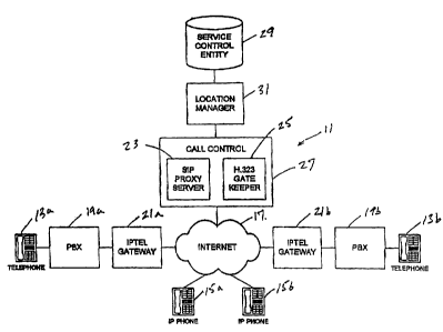
Refernng now to the drawings, and first to Fig. 1, a system according to
present
invention is designated generally by the numeral 1 1. The system 1 1 is
adapted to provide
telephony services between and among subscribers using traditional telephones
13 and
Internet telephones 15. The signaling and media for calls according to the
present invention
are transported at least in part over the Internet, indicated generally at 17.
Traditional telephones 13 are connected to Internet 17 through traditional
telephone
switching equipment, such as PBXs 19 and IP telephony gateways 21. IP
telephony
gateways 21 each include a signaling gateway (not shown) and a media gateway
(not shown).
The signaling gateway provides bidirectional translation between PSTN
telephony signaling,
such as SS7, messages and IP telephony signaling messages in protocols such as
H.323 or
Session Initiation Protocol (SIP). Typically, media gateways use one IP
signaling protocol or
the other, but not both. The media gateway provides bidirectional conversion
between time
division multiplexed (TDM) signals and IP transport packets in a protocol such
as real-time
transport protocol (RTP). IP phones 15 may be connected directly to be
Internet through a
local area network or by modem connection through an Internet service
provider.
Generally, call signaling and media are transported across Internet 17 between
ingress
IP telephony gateway 21 a and an egress IP telephony gateway 21 b. Typically,
routing
information is supplied by a proxy server, such as a SIP proxy server 23 or an
H.323
gatekeeper 25. In the SIP protocol, and invite message is sent from the
ingress IP telephony
gateway 21 a to the address of the called party at the SIP proxy server 23.
For normal calls
that do not require intelligent network services, the SIP proxy server 23
knows the address of
the called party at the egress IP telephony gateway 21b. IP call setup
signaling messages are
transported back and forth between the IP telephony gateways 21 and the SIP
proxy server 23
until the call is setup. In the present invention, the SIP proxy server 23 and
the H.323
gatekeeper 25 are combined in a call control entity 27.
SUBSTITUTE SHEET (RULE 26)
CA 02385100 2002-03-14
WO 01/22720 PCT/LTS00/26228
The proxy servers 23 and 25 cannot by themselves, handle calls that require
intelligent network services. Examples of calls requiring intelligent network
services are
"800" number calls Virtual Private Network (VNET) calls, local number portable
calls, call
forwarded calls, and the like. In traditional PSTN telephony, switches consult
service control
entities, known as service control points (SCPs), for routing information,
such as number
translation, in order to route calls properly.
The system 11 makes use of a legacy PSTN system service control entity
indicated
generally at 29, which may be an SCP: The system 11 includes a location
manager 31. which
provides alias resolution, gateway selection, and mobility management services
to the call
control entity 27, as well as accessing the service control entity 29 for such
services as VNET
and local number portability services on behalf of the call control entity 27.
The location manager 31 functions as a SIP redirect server. A redirect server
is a
server that accepts a SIP request, maps the address into zero or more new
addresses and
return are these addresses to the client. Unlike a SIP proxy server, a
redirect server does not
initiate its own SIP requests. Unlike a SIP user agent server, a redirect
server does not accept
calls. Thus, if a server of the call control entity 27 cannot send a session
initiation request to
the IP telephony gateway 21, then the server sends a session initiation
request to the called
party at the location manager 31. The location manager 31 either consults its
own database
or accesses the legacy service control entity 29 to obtain a new address for
the called party.
The location manager 31 then returns the new address to the appropriate server
of the call
control entity 27.
In a preferred embodiment of the present invention, the H.323 gatekeeper 25 is
modified to function in the SIP protocol. Thus, the H.323 gatekeeper 25
communicates with
H.323 IP telephony gateways and Internet appliances in the H.323 protocol, and
with SIP IP
telephony gateways, Internet appliances, and the location manger 31 in the SIP
protocol.
4
SUBSTITUTE SHEET (RULE 26)
CA 02385100 2002-03-14
WO 01/22720 PCT/US00/26228
Refernng now to Fig. 2, the PBX 19a sends a setup message 33 to the IP
telephony
gateway 21 a. The IP telephony gateway 21a maps of the setup message 33 into a
SIP invite
request 35 addressed to the SIP proxy server 23. The SIP proxy server 23 is
unable by itself
to process setup for a VNET call. Accordingly, the SIP proxy server 23 sends a
SIP invite
request 37 to the dialed number at the location manager 31.
Upon receipt of the invite request 37, the location manager 31 queries the
service
control entity 29 with a routing request 39. The service control entity 29
performs a data
lookup and responds to the location manager 31 with a routing response 41. The
location
manager 31 maps response 41 into a SIP temporarily moved response 43 directed
back to SIP
proxy server 23. As is well-known those skilled in the art, SIP responses are
identified by a
number, which for the case of the temporarily moved response is 302. The
response 43
provides the SIP proxy server 23 with an IP address for the called party at
the egress IP
telephony gateway 21b. Accordingly, the SIP proxy server 23 sends an invite
request 45 to
the called party at the egress IP telephony gateway 21b.
Upon receipt of the invite 45, the egress IP telephony gateway 21b sends a
setup
message 47 to the PBX 19b. When the PBX 19b rings the line of the called
party, the PBX
19b sends an alerting message 49 back to the egress IP telephony gateway 21b.
The egress IP
telephony gateway 21b then sends a SIP 180 ringing message 51 back to the SIP
proxy server
23, which in turn sends a SIP 180 ringing response 53 to the ingress IP
telephony gateway
21 a. The ingress IP telephony gateway 21 a then sends an alerting message 55
to the PBX
19a, which provides a ringing tone to the caller party. When the called party
answers, PBX
19b sends a connect message 57 to the egress IP telephony gateway 21b. The
egress IP
telephony gateway 21b in turn sends a SIP 200 OK response 59 to the SIP proxy
server23.
The proxy server 23 sends a 200 OK response 61 to the ingress IP telephony
gateway 21 a.
Upon receipt of the response 61, the ingress IP telephony gateway 21 a sends a
connect
message 63 to the PBX 19a and a SIP ACK request 65 to the SIP proxy server 23.
The SIP
5
SUBSTITUTE SHEET (RULE 26)
CA 02385100 2002-03-14
WO 01/22720 PCT/US00/26228
proxy server 23 sends an ACK request 67 to the egress IP telephony gateway 21
b and VNET
session is established.
At the conclusion of the VNET session, the called party hangs up and the PBX
19b
sends a release message 69 to the egress IP telephony gateway 21b. The egress
IP telephony
gateway 21b maps release 69 into a SIP BYE request 71 addressed to the calling
party at SIP
proxy server 23. The SIP proxy server 23 then sends a BYE request 73 to the
calling party at
the ingress IP telephony gateway 21 a. The ingress IP telephony gateway 21 a
sends a release
message 75 to the PBX 19a to terminate the call. The ingress IP telephony
gateway 21 a also
sends an ACK request 77 to the SIP proxy server 23. The SIP proxy server 23
sends an ACK
request 79 back to the egress IP gateway 21b. The SIP proxy server 23 also
sends a session
detail record 81 to an appropriate billing authority.
Refernng now to Fig. 3, in which the signaling gateway of the ingress IP
telephony
gateway 21 a uses the H.323 protocol. The PBX 19a sends a setup message 83 to
the ingress
IP telephony gateway 21 a. The ingress IP telephony gateway 21 a maps the
setup message 83
into an H.323 ARQ message 85 addressed to the H.323 gatekeeper 25. The H.323
gatekeeper
responds to message 85 with an H.323 ACF message 87. Upon receipt of message
87, the
ingress IP telephony gateway 21a sends an H.323 setup message 89 to gatekeeper
25. The
H.323 gatekeeper 25 is unable by itself to process setup for a VNET call.
Accordingly, the
H.323 gatekeeper 25 sends a SIP invite request 91 to the dialed number at the
location
20 manager 31.
Upon receipt of invite request 91, the location manager 31 queries the service
control
entity 29 with routing request 93. The service control entity 29 performs a
data lookup and
responds to the location manager 31 with a routing response 95. The location
manager 31
determines that the call should be routed to the called party at the egress IP
telephony
25 gateway 21b and sends a SIP 305 temporarily moved response 97 back to the
H.323
gatekeeper 25. The H.323 gatekeeper 25 sends a SIP invite request 99 to the
called party at
6
SUBSTITUTE SHEET (RULE 26)
CA 02385100 2002-03-14
WO 01/22720 PCT/US00/26228
the egress IP telephony gateway 21b. Upon receipt of the SIP invite request
99, the egress IP
telephony gateway 21b sends a setup message 101 to the PBX 19b. When the PBX
19b rings
the line of the called party, the PBX 19b sends an alerting message 103 back
to the egress IP
telephony gateway 21b. The egress IP telephony gateway 21b then sends a SIP
180 ringing
message 105 back to the H.323 gatekeeper 25, which in turn sends a H.323
alerting message
107 to the ingress IP telephony gateway 21 a. The ingress IP telephony gateway
21 a then
sends an alerting message 109 to PBX 19a, which provides a ringing tone to the
calling party.
When the called party answers, the PBX 19b sends a connect message 111 to the
egress IP
telephony gateway 21b. The egress IP telephony gateway 21b in turn sends a SIP
200 OK
response 113 to the H.323 gatekeeper 25. The H.323 gatekeeper 25 sends an
H.323 connect
message 115 to the ingress IP telephony gateway 21 a and a SIP ACK request 116
back to the
egress IP telephony gateway 21b. Upon receipt of the message 1 I5, the ingress
IP telephony
gateway 21 a sends a connect message 117 to the PBX 19a and the VNET session
is
established.
At the conclusion of the VNET session, the called party hangs up and the PBX I
9b
sends a release message 119 to gateway 21b. Gateway 21b maps release 119 into
a SIP BYE
request 121 addressed to the calling party at the H.323 gatekeeper 25. The
H.323 gatekeeper
then sends an H.323 release message 123 to the calling party at the ingress IP
telephony
gateway 21 a and a SIP ACK request 124 back to the egress IP telephony gateway
21b. The
20 ingress IP telephony gateway 21 a sends a release message 125 to the PBX
19a to terminate
the call. According to the H.323 protocol, at the conclusion of the session,
the H.323
gatekeeper 25 sends a disengage request 127 to the ingress IP telephony
gateway 21 a, which
responds with a disengage confirm 129. Then the H.323 gatekeeper 25 sends an
end session
command 131 to the ingress IP telephony gateway 21 a, which responds with an
end session
25 command ACK 133. The H.323 gatekeeper 25 then sends a session detail record
135 to the
appropriate billing authority.
7
SUBSTITUTE SHEET (RULE 26)
CA 02385100 2002-03-14
WO 01/22720 PCT/US00/26228
From the foregoing, it may be seen that the present invention provides a
method and
system for providing intelligent network services in an IP telephony system.
The location
manager of the present invention functions as a SIP redirect server to provide
signaling
routing information to proxy servers. Those skilled in the art will recognize
alternative
embodiments given the benefit of the foregoing disclosure. Accordingly, the
foregoing is
intended for purposes of illustration and not of limitation.
SUBSTITUTE SHEET (RULE 26)