Note: Descriptions are shown in the official language in which they were submitted.
CA 02385209 2007-02-16
1
A METHOD IN A SODA RECOVERY BOILER, AND A SODA RECOVERY
BOILER
FIELD OF THE INVENTION
The invention relates to a method in a soda recovery
boiler in which flue gases are led through a so-called
economizer to recover heat from flue gases. The invention
also relates to a soda recovery boiler comprising a
furnace and an economizer which is arranged in the flow
of flue gases to recover heat from flue gases exiting the
furnace.
BACKGROUND OF THE INVENTION
In chemical pulping industry, soda recovery boilers are
used not only for the recovery of chemicals but also for
the production of energy. As to the general operating
principle and structure of soda recovery boilers,
reference is made, for example, to European patent 737260
and US patent 6,178,924.
The soda recovery boiler comprises a furnace, a system
for feeding boiler supply water, a superheater at the
upper part of the furnace, possibly a boiler bank (array
of boiler tubes), and, after these in the flowing
direction of flue gases, a so-called economizer for the
recovery of thermal energy contained in the flue gases.
The soda recovery boiler also comprises a combustion air
supply for introducing the required combustion air in the
furnace. Leading the supply water through different parts
of the boiler produces high-pressure steam which is at a
high temperature and can be used for the production of
electricity with a steam turbine.
CA 02385209 2002-05-06
2
The aim is to utilize the heat contained in the flue
gases in the economizer, in which it is used for heating
the supply water before it is passed to steam production,
as described for exarnple in LTS patent 5, 769, 156.
In soda recovery boilers, it is also kriown to cool the
flue gases with a so-called circulation water cooler for
flue gases, if the supply water is too hot for bringing
the flue gases to a sufficientl_y low temperature, the
circulation water cooler for flue gases being connected
to the supply water flow circuit: in the soda recovery
boiler. The supply water is normally heated in a supply
water tank by means of bleed steam. extracted from a steam
turbine. In soda recovery boilers, the temperature of the
supply water tank must ofteri be reduced by throttling the
steam entering it, to make the supply water sufficiently
cold to cool the flue gases. At present, heat exchange
systems in soda recovery boilers do n.ot take into account
the efficiency in view of the production of electricity.
The throttling of steam and the iritr_oduction of heat in
the supply water at a cold temperature is not
advantageous for the yield of electricity from the steam
process.
BRIEF SUMMARY OF THE INVENTION
It is an aim of the invention to present a method in a
soda recovery boiler to improve the efficiency of the
production of electricity. It is another aim of the
:30 invention to present an improved soda recovery boiler for
the above-mentioned purpose.
In the method acco:rding to the invention, the final
cooling of the fluE:~ gases is performed by a circulation
water cooler, separately from the supply water system.
Consequently, the flue gases are not cooled entirely with
supply water. The circulation water cooler is used to
CA 02385209 2002-05-06
3
introduce the heat of the flue aases to the combustion
air instead of the supply water. Pre-heating of the
supply water is ca:rried out with flue gases before said
circulation water cooler, seen in their flowing
direction; that is, the flue gases are cooled only in
part with supply water, at the stage where they are
initially at a highe.-- temperature.
The higher the ave:r_a_qe temperature at which the heat is
introduced from the flue gases of the soda recovery
boiler to the suppl~.l water, the better is the yield of
electricity. Consequently, it is advantageous to cool the
flue gases with supply water until their last cooling
stage which is accomplished with the circulation water
cooler. The supply water used for cooling the flue gases
is preferably preheated with high-pressure steam
originating in the steam production of the same boiler,
for example, with bleed steam and/or back-pressure steam
of a steam turbine. The heat recovered by the circulation
water cooler in the last cooling stage of the flue qases
can be used to r-ieat the combustion air to a high
temperature, and it can be heated further with high-
pressure steam.
;25 In the economizer of the soda recovery boiler according
to the invention, there is, i_n the last stage, a
circulation water economizer connected to the circulation
water cooler of the flue gases, where the water is
circulated through a heat exchanqer, that is in a heat
transfer connection with a combustion air supply channel,
and in the supply water economizer stage preceding said
circulation water ec;onomizer, there is a heat transfer
arrangement for the transfer of heat from the flue gases
to the supply water.
:35
CA 02385209 2002-05-06
4
BRIEF DESCRIPTION OF THE DRAWINGS
In the following, the invention will be described in more
detail with reference to the appended drawings, in which
Fig. 1 illustrates schematically a method according to
the invention for the transfer of heat from flue
gases to combustion air and supply water,
Fig. 2 illustrates the thermal powers of flue gas,
water and air as a function of temperature in
the method. of Fig. 1,
Fig. 3 shows another method according to the invention,
Fig. 4 illustrates the thermal powers of flue gas,
water and air as a function of temperature in
the method. of Fig. 3,
Fig. 5 illustrates, for comparison, a method of prior
art, and
Fig. 6 illustrates the thermal powers of flue gas,
water and air as a function of temperature in
the method of Fig. S.
DETAILED DESCRIPTION OF THE INVENTION
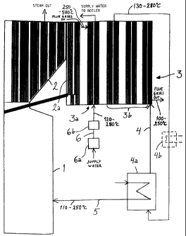
Figure 1 shows a soda recovery boiler in a schematic
view. The soda recc:>very boiler comprises a furnace 1, in
which the productior._ of thermal energy and the recovery
of chemicals from spent liquor of chemical pulp
production takes place in a knowri way, above the furnace
a superheater 2 for superheating steam, a boiler bank 2a,
which is an array of boiler tubes, and after the boiler
bank a so-called ecoi-iomizer 3, in whose successive stages
the flue gases exiting the furnace are cooled by means of
CA 02385209 2002-05-06
water flowing in a construction of vertical tubes and
being heated.
The economizer 3 is located in the upper part of the
5 boiler next to the superheater and the boiler bank and
comprises successive parts (stages), in which the average
temperature of the flue gases is reduced by cooling.
After the last stage of the economizer the flue gases
enter the flue channel. The last stage of the economizer,
i.e. the last economizer packets are cooled by a
circulation water cooler 4 showri in Fig. 1. The last
three vertical tube type parts (vertical tube packets) of
the economizer thus make up the last cooling stage 3b, in
which the heat transfer takes place by a counter-current
principle to the water flowing inside the tubes. The
circulation water cooler 4 for flow gases comprises a
circulation water economizer 3b and a heat exchanger 4a,
through which is passed the circulation water which
cooled the flue gases and was simultaneously heated in
the economizer. Through the heat exchanger 4a is
introduced a combustion air channel 5 which supplies
combustion air to the furnace 1 and in which the
combustion air is heated.
By the above-descri.bed solution, the heat recovered from
the flue gases in the economizer at a relatively low
temperature is transferred to the combustion air.
Before the above-described final stage in the flowing
direction of the f:lue gases, the economizer 3 includes
heating of the supply water (stage 3a) . A supply water
line 6 to the boiler passes through the vertical tube
packets of the economizer. 'The supply water to be
introduced in the boiler along the supply water line 6 is
heated in the vertical tube type construction of the
economizer 3; that is, heat is transferred from the flue
gases to the supply water at a higher temperature than to
CA 02385209 2007-02-16
6
the circulation water which heats the combustion air.
Furthermore, the supply water is already preheated in the
supply water tank to a temperature corresponding to the
steam back-pressure of the pulp mill, and the heating
before the introduction of the supply water in the part
of the economizer is performed with bleed steam and/or
back-pressure steam of the steam turbine that is arranged
to produce electricity by the steam produced by the
boiler. Heat exchangers for implementing this, placed
before the economizer in the supply water line 6 after
the supply water tank, are indicated with reference
numerals 6a and 6b.
Consequently, when studying the flow of flue gases in the
economizer 3, it can be stated that the flue gases are
first cooled at a higher temperature with supply water
(stage 3a), which has been preheated by steam from the
steam production of the boiler, and the flue gases are
then cooled with circulation water which will transfer
heat to combustion air (stage 3b). The first section of
the economizer can thus be called a supply water
economizer, and the second section of the economizer a
circulation water economizer. In both cases, the cooling
takes place by the counter-current principle in the parts
of vertical tube construction in the economizer. Figure 1
shows the circulation water cooler 4 for flue gases,
whose economizer part comprises three circulation water
economizer packets (stage 3b) and whose supply water part
comprises one packet (stage 3a). The division can also be
made in another way; for example, the circulation water
economizer comprises only one packet of vertical tubes
and the supply water economizer comprises two packets of
vertical tubes.
Figure 1 shows the inlet temperature of flue gases
entering the economizer 3 after the boiler bank 2a, the
outlet temperature of flue gases exiting the
CA 02385209 2002-05-06
7
economizer 3, the inlet temperature of supply water
entering the supply water economizer, the outlet
temperature of circulation water of the circulation water
cooler 4 exiting the circulation water economizer, and
the inlet temperatu.re of combustion air after the heat
exchanger. The temperatures are indicated as temperature
ranges.
If the heat absorption capacity of the combustion air is
not sufficient, or if there are other reasons to use the
heat of the circulation water for other purposes than for
heating air, it is possible to couple an auxiliary heat
exchanger at ariy location in the circulation water
circuit, either in parallel or in series with the heat
exchanger 4a heatinq the combust.ion air. The auxiliary
heat exchanger serves to cool the circulation water
further, for example by water. At the same time, hot
water is produced. In Fig. 1, such an auxiliary heat
exchanger 4b is indicated with a broken line.
Figure 2 shows the thermal powers of the material flows
(flue gas, water and. combustion air) as a function of
temperature in the system of Fig. 1. The curve
illustrating the heating of water consists of two
material flows: the heating of circulation water iri the
last stage of the cooling of the flue gases, and the
heating of supply water in the stage preceding the
cooling of flue qases and its later boiling in the
boiler.
Figure 3 shows another alternative. Here, the same
elements are indic<:rted with the same reference numerals
as in Fig. 1. Combustion air i_s heated by a circulation
water cooler passing through the l.ast cooling stage :3b of
flue gases, as above (the part of vertical tube
construction formin(; the last st:age 3b) . The preceding
part of the economizer 3 of the vertical tube
CA 02385209 2002-05-06
8
construction is used for heating preheated supply water
whose temperature is thereafter raised by bleed steam
and/or back-pressure steam of the steam turbine (heat
exchanger 6a in the supply water line 6), and after this,
it is led to the part of the vertical t:ube construction
preceding said part in the economizer 3. These parts
constitute the first stage 3a of the economizer. The flue
gases are now cooled in three stages by the circulation
water cooler and supply water: iri the first stage, seen
in their flow direction, with supply water whose
temperature has been raised by steam from the steam
production of the same boiler, iri the second stage with
the same supply water which is at a lower temperature,
and in the final stage by the circulation water cooler 4.
Thus, whereas in Fi.g. 1 the supply water is preheated by
steam in one or several heat exchangers before entering
the economizer, in Fig. 3 the supply water is heated by
steam in a separate intermediate s-tage between two stages
of the economizer wh:ile being out of the economizer.
Figure 3 also shows how combustion ai.r can also be heated
after the heat exchanger 4a with bleed steam and/or back-
pressure steam of the steam turbine (heat exchanger 5a in
the combustion a.:Lr channel 5). Figure 3 shows the
temperatures of the material flows by the same principle
as in Fig. 1.
Figure 4 shows the system of Fig. 3 by the same principle
as in Fig. 2. What is in common. w:ith the system of Fig. 1
is that also here the flue gases are cooled in the last
stage by circulation water, from which the heat is
transferred to combustion air. The difference is that the
supply water is Led by the countercurrent principle
through two successive cooling stages of flue gases, by
raising its temperature with high-pressure steam between
the stages.
CA 02385209 2002-05-06
9
It is understood that heat transfer from flue gases to
the water in the economizer and from steam to water in
heat exchangers takes place betweeri separated streams of
gases and water and steam and water, respectively,
through walls separating these streams from each other.
For comparison, Fiqs. 5 and 6 show the method known from
Finnish patent FI-101163 and the corresponding European
patent EP-724683, in which the fl-ae gases are cooled with
supply water in a].l the stages in the economizer 3 by
raising the temperature of the supp:Ly water betweeri the
stages by means of back-pressure steam and/or bleed steam
of the steam turbine, and the combustion air is pre-
heated by steam only (heat exchangers 5a, 5b and 5c).
The invention makes it possible to improve the production
of electricity (electricity-to-heat production ratio) in
the soda recovery boiler. In the _soda recovery boiler, it
is possible to build a sufficiently large economizer, to
which the supply w,ater can be introduced in a preheated
state.
The invention can be applied both in new soda recovery
boilers and in o1d soda recovery boilers after
modifications. The size of the economizer can thereby be
increased, and heating of the supply water with bleed
steam can be coupled between the parts of the economizer.
The last part of the economizer can be coupled to operate
by circulation water, and this circulation water can be
coupled to the preheating of combusti_on air.
The invention is riot limited to the above-presented
embodying examples but it can be modified within the
scope of the claims.
Above, the invention has been described in connection
with soda recovery boilers, to which also the claims
CA 02385209 2002-05-06
relate. The arrangernent accordinq to the invention can
also be used in other boilers involvinq the problem of
fouling properties of the flue gases.