Note: Descriptions are shown in the official language in which they were submitted.
CA 02385471 2002-03-21
WO 01/25602 PCT/US00/26606
A CATALYTIC REACTOR FOR PROMOTING A CHEMICAL
REACTION ON A FLUID PASSING THERETHROUGH
CROSS-REFERENCES
This invention was made with government support under NASA
SBIR Phase II contract NASS-40573. The U.S. government has certain rights in
this
invention.
BACKGROUND OF THE INVENTION
FIELD OF THE INVENTION
The present invention is a catalytic reactor for promoting a chemical
reaction on a fluid passing therethrough. More specifically, the apparatus is
a
structure for step-wise heating of a fluid passing therethrough such that the
fluid
obtains or maintains a temperature wherein the desired chemical reaction, in
the
presence of a catalyst, can occur.
BRIEF DESCRIPTION OF THE RELATED ART
Catalytically supported reactions are used in numerous applications,
with the automotive converter being one of the more well known. Catalyst
characteristics dictate that these reactions occur within a given temperature
range
with the operational temperature range being chemistry dependent. When a
catalyst reaches its operational temperature range it is said to light-off;
prior to
reaching light-off the catalyst is too cold to support the desired reaction.
After
light-off the catalyst temperature must be maintained to support the reaction.
Several methods have been employed to raise the temperature of the
catalyst to achieve light-off and/or maintain operational temperature. One
common method uses the heat energy in the fluid on which the chemical reaction
is
to occur. This approach, common in automotive converters, imparts the heat in
the
exhaust gas, resulting from the combustion in the engine, to the catalyst in
the
downstream catalytic converter.
A second method which is fluid independent employs an auxiliary
heat source. The most common auxiliary source being powered by electricity. In
this method, the substrate that supports the catalyst is an electrically
conducting
CA 02385471 2002-03-21
WO 01/25602 2 PCT/US00/26606
material that heats up by its electrical resistance when an electric potential
is put
across the substrate. Auxiliary heating sources are used primarily where the
extraction of heat from the fluid is either too slow to effectuate a timely
light-off of
the catalyst, or the heat of the fluid is below the light-off temperature of
the
catalyst.
Auxiliary heating sources, as the name implies, are additional
systems to the primary system. It is, therefore, critical that these auxiliary
heating
systems be highly efficient in bringing the catalyst to or maintaining the
catalyst at
the appropriate operational temperature. The art is well aware of the
efficiency of
extremely short-channel, metal-substrate catalysts. When these catalysts are
bundled, however, the resulting elements have extremely low resistance thus
making electrical heating impractical, due to large current requirements for a
given
electrical potential resulting in excessive power supplies and cables.
Currently,
spacing is used to solve this problem, but the resulting devices are extremely
long.
A method of efficient bundling that permits auxiliary electrical resistive
heating is
required.
SUMMARY OF THE INVENTION
The present invention is a catalytic reactor for promoting a chemical
reaction on a fluid passing therethrough. The invention is comprised of a
plurality
of heater elements with each element having multiple flow channels. The
channels
of the heater elements are aligned such that a fluid passing through the
reactor
passes through each heater element in turn, thereby step-wise heating the
fluid.
In the present embodiment of the invention, the heater element is
made of a single piece of expanded metal. This, however, should not be
limiting.
For this invention a heater element can have any number of layers, for example
two
or three layers of expanded metal. A heater element is simply an element that
heats up uniformly as a unit.
The heater elements are electrically isolated from one another by at
least one insulator. Like the heater element, the insulator has multiple flow
channels. The insulator flow channels are oriented to the flow channels of the
heater elements, such that the fluid flows through both the heater element and
the
insulator.
The present invention can also incorporate a catalytic feature. The
catalytic feature can be associated with the at least one heater element, at
least one
CA 02385471 2004-07-13
3
insulator element, a separate downstream catalyst or any combination of the
above. The present embodiment incorporates a catalyst feature in the heater
elements, the insulator elements and a downstream catalyst. In this
embodiment, the insulator has the dual function of insulating and supporting
the catalyst.
The heater elements of the present invention are made from
material that is electrically conductive. The insulators are made from woven
silica yarn, which is electrically non-conductive. The heater elements are
connected electrically, in series being preferred, with the insulators
assuring
no electrical short circuits between the heater elements. For operation, each
end of the electrical circuit is connected to an electrical power source. In
the
case of the present invention, the power source was direct current.
The catalyst chosen for use in the invention is application
dependent. The specific application of the present invention is as a
component of an air purification system, therefore the catalyst employed has
as its active ingredients platinum and palladium. For the present application,
the catalyst was deposited on both the heater elements and the insulator
elements.
To provide a sealed flow path through the catalytic reactor,
gaskets were incorporated. A gasket is only one method of sealing the reactor
flow path. Gaskets are used as required.
In the present embodiment of the invention, three downstream
catalysts were added. The downstream catalyst or catalysts can be of any
design. In the present invention, the first downstream catalyst was merely
additional catalytically coated insulator elements. Again, gaskets were
employed to assure the integrity of the flow path. The second and third
downstream catalyst were packets of Microlith elements, such as those found
in US Patent 5,051,241.
CA 02385471 2004-07-13
3a
According to an aspect of the present invention, there is
provided a catalytic reactor for promoting a chemical reaction on a fluid
passing therethrough comprising: at least two heater elements, each defining
a plurality of first flow channels;
catalytic means associated with at least one of the at least two
heater elements for promoting a chemical reaction with the fluid passing
therethrough;
at least one insulator defining a plurality of second flow
channels positioned between any two heater elements, wherein the heater
elements and at least one insulator are compressed together;
the first and second flow channels being aligned in a common
direction of flow such that the fluid passes in turn through the heater
elements and at least one the insulator;
and wherein the heater elements, during operation, impart
sufficient heat to the fluid to promote catalysis of at least a portion of the
fluid
passing through the reactor.
According to another aspect of the present invention, there is
provided a catalytic reactor for promoting a chemical reaction on a fluid
passing therethrough comprising:
at least two heater elements, each defining a plurality of first
flow channels;
at least one insulator defining a plurality of second flow
channels positioned between any two heater elements wherein the heater
elements and at least one insulator are compressed together;
catalytic means associated with at least one of the at least one
insulator for promoting a chemical reaction with the fluid passing
therethrough the insulator;
the first and second flow channels being aligned in a common
direction of flow such that the fluid passes in turn through the heater
elements and the at least one insulator; and wherein the heater elements,
CA 02385471 2004-07-13
3b
during operation, impart sufficient heat to the fluid to promote catalysis of
at
least a portion of the fluid passing through the reactor.
According to a further aspect of the present invention, there is
provided a catalytic reactor comprising:
at least two heater elements, each defining a plurality of first
flow channels;
at least one insulator defining a plurality of second flow
channels positioned between any two heater elements, wherein the heater
elements and at least one insulator are compressed together;
the first and second flow channels being aligned in a common
direction of flow such that the fluid passes in turn through the heater
elements and the at least one insulator;
at least one catalyst located downstream of the heater elements;
and wherein the heater elements, during operation, impart
sufficient heat to the fluid to promote catalysis of at least a portion of the
fluid
passing through the reactor.
BRIEF DESCRIPTION OF THE DRAWINGS
An embodiment of the present invention will now be described
more fully with reference to the accompanying drawing in which:
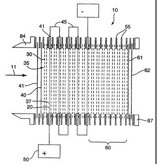
Figure 1 is a cross-sectional representation of the present
invention. For illustration purposes space has been left between the various
elements.
CA 02385471 2002-03-21
4
DETAILED DESCRIPTION OF THE PREFERRED
EMBODIMENTS OF THE INVENTION
Figure 1 is a cross-sectional representation of the catalytic reactor 10.
Catalytic reactor 10 is composed of at least two heater elements 20, each
defining a
plurality of first flow channels 37, with each heater element separated from
the other
by at least one insulator element 30, each defining a plurality of second flow
channels 35. The specific number of heater elements is application dependent
based
on the desired temperature rise. In the current embodiment, the heater
elements 20
are electrically connected in series by electrical connectors 45 such that a
single
electrical potential 50 can be used to resistively heat all the heater
elements. The
channels of the heater elements 20 and at least one insulator element 30 are
aligned
in a common direction of flow 11, such that the gas passes through both the
heater
elements 20 and the insulator elements 30. In the case of the present
embodiment,
gaskets 55 are employed where necessary to maintain the integrity of the flow
path.
The heater elements 20 are catalytically active as are at least one
insulator element 30. The catalyst or catalysts selected are application
dependent
and are selected just as one skilled in the art would select a catalyst.
Catalytic
activity can be achieved in numerous ways such as deposition of the catalyst
on the a
support, such as used in this embodiment, or making the support from catalytic
material or material incorporating catalytic material.
In the embodiment shown, the invention is placed into a mufti-stage
catalytic reactor. Upstream of the invention are a first upstream catalyst 41
and a
second upstream catalyst 40. Downstream of the invention are three catalysts -
a
first downstream catalyst 60, a second downstream catalyst 61, and a third
downstream catalyst 62. The use of mufti-stage catalyst is application
dependent
and is shown here to give an appreciation for how the invention might be used
in a
mufti-stage catalytic reactor. It should be noted that at least one insulator
element 30
and gaskets 55 were employed as needed to assure the electrical isolation of
heater
elements 20 and the integrity to the flow path.
The number of heater elements is a function of the desired temperature
rise in the gas passing therethrough. In one application a temperature rise of
40
degrees C was desired. The heaters were to be heated by electrical resistance.
The
electrical constants were as follows: Operating voltage (V) -- 28 VDC; Target
power
(P) -- 168 Watts (~ 8 Watts); Maximum length of each heater element -- 3"; and
Maximum width of each heater element -- 3.5". These requirements dictated that
the
Substitute Sheet
CA 02385471 2002-03-21
resistance (R) for the entire heater assembly had to be 4.45 S2 (R = V_/P). As
the
device had to fit in a cylinder that limited the width of the elements to
approximately 3.5 inches, the variables in the reactor design were the length
and
width of each heater element, and the total number of heater elements. As
resistance
5 is directly proportional to the length and inversely proportional to the
width and the
material has unit cells in both directions, the resistance can be controlled
only down
to the precision of the cell size by choosing the length or width of the
material. The
approximate resistance of the chosen material for a width of 3.5" was measured
to be
0.30 S~/in. The heater was sized to have five, 3.5 inch wide elements, each 3
inches
in length, connected in series to give a total length of 15 inches. This
results in a total
resistance of 4.5 S2, and a predicted power usage of 174 Watts at 28 VDC,
which is
within the range for the target power.
The invention is constructed by stacking the heater elements, gaskets,
and insulators as shown in figure 1. In the present embodiment, the heater
elements
were connected in electrical series by electrical connectors 45 using the
previously
described terminals 41. A series connection was chosen since the heater
elements
have a low resistance and a series configuration increase the total resistance
of the
device. Based on a fixed voltage for the application, this lowered the
amperage
requirement. Wiring of the elements in series, parallel, or some combination
is,
however, application dependent and standard heater design procedures can be
employed. The at least one insulator element 30 in the present invention are
used to
assure that a short circuit does not exist between the adjacent heater
elements,
therefore at least one insulator element 30 must be placed between any two
heater
elements.
The invention is shown with two upstream catalysts and three
downstream catalysts. The number and configuration is application dependent
and
presented here for illustration only. The first downstream catalyst is
constructed
from additional insulator elements 30 and gaskets 55. The first upstream
catalyst 41
and second downstream catalyst 62 are constructed from woven wire mesh.
The entire assembly is compressed between the two end plates, 84 and
87 by bolts (not shown), forming an integral flow path, such that the gas
enters the
assembly through the upstream end plate 84 and exiks through the downstream
end
plate 87.
Substitute Sheet
CA 02385471 2002-03-21
6
Although the present invention has been described in considerable
detail with reference to certain preferred versions thereof, other versions
are
possible. Therefore, the spirit and scope of the appended claims should not be
limited to the description of the preferred version contained herein.
Substitute Sheet