Note: Descriptions are shown in the official language in which they were submitted.
CA 02385803 2002-05-10
RELEASABLE AND SECURABLE MOBILE
[0001] The invention relates to an entertainment device that includes a child
support with an
entertainment member attached to the child support. The entertainment member
is preferably .
releasable and securable to a cradle, bassinet, swing, bouncer, car seat, or
other child support
device. More particularly, the invention is directed to a child's mobile that
rotates freely from a
portion of a cradle, bassinet, swing, bouncer, car seat, etc., and is quickly
and easily releasable
from and securable to the cradle, bassinet, swing, car seat, etc.
[0002) Conventional mobiles for children typically are secured to cribs and
play pens or
suspended from the ceiling above a location where a child lays or sits. These
mobiles often have
elaborate mechanisms for attachment to the crib or ceiling and may have toys
or teething objects
hanging from long strings extending from the ends of the mobile arms. A string
or rod often
suspends these mobiles so that the mobile can freely rotate as directed by a
child. Some
conventional mobiles are motorized and can rotate in a predetermined direction
for visual
stimulation.
[0003] The somewhat complicated assembly for attaching conventional mobiles to
a supporting
structure results in an increase in manufacturing cost and decreases the
devices' appeal to
customers. Furthermore, some conventional mobiles require a significant amount
of clearance
space between their attachment to a supporting structure and the mobile
itself, making the
conventional mobile inconvenient for use with child supports designed for
smaller spaces.
Additional clearance space is also required between the bottom of the mobile
and the child,
thereby fiirther limiting the options where conventional mobiles can be
placed.
[0004] Conventional cradles, bassinets, swings, bouncers, car seats, or other
child support
devices are designed to restrain the child and provide a safe environment for
the child to rock,
sleep, swing, bounce, and motor along. The sensory stimulation from rocking in
a cradle,
2
CA 02385803 2002-05-10
swinging in a seat, jumping in a bouncer, or motoring in an automobile can be
beneficial to the
child's development. However, after extended periods of time restrained in the
child support
device a child can become bored and irntable. Therefore, it is desirable to
provide an easily
securable entertainment device that can be quickly attached to a child support
for the child's
amusement, and can be detached easily for facilitating removal of the child
from the child
support.
SUMMARY OF THE INVENTION
[0005] In the invention, an entertainment device can include an entertainment
member, such as a
freely rotatable soft mobile, that can be quickly and easily attached to and
removed from a child
support device. Thus, the mobile can be attached so that a child located in
the child support
device can play with the mobile while seated, and can be easily detached from
the child support
device to facilitate removing the child from the child support. The
entertainment member can
include connection means that has a low profile such that the entertainment
member can be
located in relatively small spaces, such as between a swing and its overhead
support member.
[0006) To achieve these and other advantages and in accordance with the
purpose of the
invention, as embodied and broadly described, the invention provides an
entertainment device
that can include a child support device having a receiving member and an
entertainment member,
e.g., a child's mobile, which includes a connector structure for quick and
easy attachment to the
receiving member on the child support device.
[0007] In another aspect of the invention, the entertainment device can
include an entertainment
member that is releasably attached to a child support device, for example a
cradle, bassinet,
swing, bouncer, or car seat. The child support device can have an upper
structure located above
the child when the child is positioned within the child support device. A
receiving member can
be attached to the upper structure of the child support device and be
engagable with a connector
structure on the entertainment member. The receiving member can be releasably
securable with
the connector structure, and configured to prevent the connector structure
from disengaging from
the receiving member while allowing the connector structure to freely rotate
within the receiving
3
CA 02385803 2002-05-10
member. The connector structure can be slid past the narrowest aperture of the
receiving
member until it snaps into or out of a locked position on the receiving member
to secure or
release the entertainment member with the receiving member.
[0008] In another aspect of the invention, the entertainment device can
include means for
connecting a rotary entertainment member with a connection structure such that
the rotary
entertainment member is prevented from translating with respect to the
connection structure and
can freely rotate within and be selectively removable from the connection
structure.
[0009] In yet another aspect of the invention, a method for connecting a
rotary entertainment
member to another structure is disclosed. The method can include providing a
rotary
entertainment member with a connector and securing it to a connection
structure while
permitting the connector to freely rotate with respect to the connection
structure.
(0010] It is to be understood that the foregoing general description and the
following detailed
description are exemplary and explanatory and are intended to provide further
explanation of the
invention as claimed.
DRIEF DESCRIPTION OF THE DRAWINGS
[0011 ] The accompanying drawings, which are included to provide further
understanding of the
invention and are incorporated in and constitute a part of the specification,
illustrate preferred
embodiments of the invention and together with the detailed description below
serve to explain
the principles of the invention. In the drawings:
[0012] Fig. 1 a is a front elevation view of an entertainment device made in
accordance with an
embodiment of the invention.
[0013] Fig. 1b is a front elevation view of an entertainment device made in
accordance with
another embodiment of the invention.
[0014] Fig. 2 is a top perspective view of the entertainment member including
the connector
structure and attached soft toys of the entertainment device as shown in Fig.
1 a.
[0015] Fig. 3 is a bottom perspective view of the entertainment member of the
entertainment
device as shown in Fig. 1 a.
4
CA 02385803 2005-04-06
(0016] Fig. 4 is a perspective view of the upper structure and rE;ceiving
member of the
entertainment device as shown in Fig. ~1 a.
[0017) Fig. 5. is a crass-section view of the connector structure including
the button-like
protuberance and shaft of the entertainment member taken along line V-V of
Fig. 2.
[0018) Fig. 6 is a top view of the entertainment member including the
connector structure and
attached soft toys of the entertainment device as shown in Fig. 1b.
[0019) Fig. 7 is a cross section view taken along line VII-VII of Fig. 6.
DETAILED DESCRIPTION OF THE PREFERRED EMBODIMENTS
[0020] Reference will now be made in detail to the present preferred
embodiments of the
invention, examples of which are illustrated in the accompanying drawings.
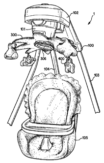
[0021) Fig. la shows an entertainment device 1 including an entertainment
member 300 formed
as a mobile and a child support device 100 formed as a child swing. The child
support device
100 can be formed as a cradle swing, such as those shown in U.S. Patent Nos.
5,803,817 and
6,027,409. The child support device 100 preferably includes support
members 103 that support an upper housing 102, swing arm 104
and swing seat 105. The upper housing 102 can include a driving device that
provides motion to
the swing arm 104 and swing seat 105. An upper structure 101 of the upper
housing 102 .
includes a surface from which the entertainment member 300 may be attached to
the child
support device 100. The entertainment member 300 may be a freely rotatable
soft mobile that is
located within reach of a child located in the swing seat 105. Several hanging
structures 400
(e.g., soft toys) can be attached to the entertainment member 300 to entertain
a child located in
the swing seat 105.
[0022) Fig. 1b shows another preferred embodiment of the invention. The
entertainment device
1 includes an entertainment member 300 that is covered with a soft goods
padding 309 and
includes hanging structures 400 that are attached directly to the ;soft goods
padding 309 by fabric
strips 314.
CA 02385803 2005-04-06
[0023] Fig. 2, is a top perspective view of the entertainment member 300 of
Fig. la. The
entertainment member 300 can include a connector structure 302 located at a
center of rotation
of the body portion 315 of the entertainment member 300. A plurality of
banging structures.400
formed as soft toys 401 can be releasably attached to entertainment members
304 located around
the periphery of the body portion 315. The soft toys 401 can be attached. to a
piece of Velcro
402 that can be mated with a corresponding piece of Velcro~ attached to the
ei~d of an
entertainment member forger 304. The distance between the end of the
entertainment member ,
forger 304 and each soft toy 401 can be adjusted by attaching the Velcro at
different
locations along the Velcro~ piece 402. Although this distance may vary, the
ent~rtainrr~e°nt
member 300 maintains a low profile in comparison to conventional mobiles. An
entertainment
member-palm area 301 and a connector structure 302 can be located.at a center
of the plurality of
entertainment member fingers 304. The connector structure 302 preferably
includes a button-
like protuberance 303 that allows the entertainment member 300 to rotate
freelywithin a
receiving member 200 secured to the child support device 100.
[0024] Fig. 3 is a perspective bottom view of the entertainment member 300 of
Fig, la: A
variety of entertainment structures, such as reflective surface 306, can be
attached to the
underside of the entertainment member 300 to further stimulate a child located
on the
entertainment device.
[0025] Fig. 4 shows the receiving member 200, which can be attached to the
upper structure 101
of the child support device 100. The receiving member 200 preferably has a U-
shaped slot
aperture 204 that has a width and thickness slightly greater than the button-
like protuberance 303
of the connector structure 302. The button-like protuberance 303 may be slid
into or out of the
U-shaped slot aperture 204 with relative ease. The receiving member can
include guiding ramp
surfaces 203 and restrictive ramp surfaces 202. The guiding ramp surfaces 203
are spaced from
each other at a distance that is slightly larger than the outer diameter of
the shaft 305 of
connector structure 302. The restrictive ramp surfaces 202 are spaced from
each other at a
distance that is slightly smaller than the outer diameter of the shaft 305 of
connector structure
302. Thus, upon entry of the button-like protuberance 303 into the U-shaped
aperture slot, the
6
CA 02385803 2002-05-10
guiding ramp surfaces 203 guide the shaft 305 of the connector structure 302
towards the fixed
hole 201. In addition, upon application of a predetermined amount of force,
the restrictive ramp
surfaces 202 flex to allow passage and guide the connector structure 302 into
the fixed hole 201.
Once the connector structure 302 is located in the fixed hole 201, the
restrictive ramp surfaces
202 return to their original position to effectively lock the connector
structure 302 at a
predetermined position within the U-shaped slot 204 of the receiving member
200. The fixed
hole 201 can be slightly larger than the outer diameter of the connector
member shaft 305 such
that the connector structure 302 (and entertainment member 300) can rotate
with respect to the
receiving member 200.
[002b] Fig. 5 shows a partial cross-sectional side view of the entertainment
member taken along
line V-V of Fig. 2. The connector structure 302 can include a button-like
protuberance 303 and
shaft 305 that are integral with an attachment plate 317. The attachment plate
317 can be
secured to the paten portion 301 of the entertainment member 300 by connectors
318, such as
rivets, screws, welds, etc. The button-like protuberance 303 is sized such
that it can rotate freely
within the U-shaped aperture 204 of the receiving member 200 when the shaft
305 is secured in
the fixed hole 201.
[0027] Fig. 6 is a top view of the entertainment member 300 as shown in Fig.
1b. The
entertainment member 300 can include four fingers 304 that each has a hanging
structure 400
attached thereto by a strip of fabric 314. The soft goods 309 can include a
fabric cover 311 that
is connected to the entertainment member 300 by stitching 313. The connector
302 can be
formed as a button-like protuberance 303 and located at a center of rotation
of the entertainment
member 300.
[0028) Fig. 7 shows a partial cross-section side view of the entertainment
member 300 taken
along line VII-VII of Fig. 6. The connector structure 302 can include a button-
like protuberance
303 and shaft 305 that are integral with the body 31 S of the entertainment
member 300. The soft
goods padding 309 can include a fabric cover 311 containing a soft cushion
material 312 and can
be attached to the body 315 by stitching 313 or other attachment means, such
as glue, fasteners,
etc.
7
CA 02385803 2005-04-06
[0029] In operation, a user can quickly and repeatably attach and remove the
entertainment
member 300 to and from the child support device 100 by inserting and
"snapping" the connector
structure 302 into the receiving member 200 and removing anal "un-snapping"
the connector
structure 302 from the receiving member 200. As the shaft 305 of the connector
structure 302
passes the guide ramp surfaces.203, it pushes apart the restrictive ramp
surfaces 202 far enough
for the shaft 305 to pass into the wider fixed hole 201. Once the shaft 305 is
located within the '
fixed hole 201, the restrictive ramp surfaces 202 return to their normal shape
to hold the shaft
305 in the fined hole 201. The guide ramp surfaces 203 and the restrictive
ramp surfaces 202 are
preferably made of a flexible material that allows the restrictive ramp
surfaces 202 to deflect and
the shaft 305 to snap easily into place. Once in the fixed hole 201, the shaft
305 and the button-
like protuberance 303 can freely spin at a predetermined position with respect
to the receiving
member 200.
[0030] The position of the hanging structures 400 relative to tile seated
child may be adjusted by
attaching the VelcroC~ pieces 402 at different positions along Velcro - ~
~t~'t~t
member 300 is then available to be enjoyed by the child as it sits or swings
in the child support
device.
[0031] The entertainment member is also easily detached from the child support
device. When
the entertainment member 300 is snapped-out of the fixed hole; 201, the
flexible restrictive ramp
surfaces 202 deflect far enough for the shaft 305 to pass the re strictive and
guide ramp surfaces,
202 and 203, respectively. The entertainment member 300 can then be set aside
so that the user'
can remove the child from the child support device 100.
(0032] Various modifications of the entertainment devices 1 shown in Figs. la-
7 can be made
without departing from the spirit and scope of the invention. For example, the
eight-point star
shaped freely rotatable soft mobile shown in Fig. 2 is just one embodiment of
the entertainment
member 300 of the invention. Numerous other shapes, sizes, colors, and
patterns are
contemplated that fall within the scope of the present invention. For example,
the entertainment
member may include a propeller shaped mobile with different colors and
patterns displayed on
each blade. Aviation motif soft toys could also be provided for hanging from
each of the blades.
8
CA 02385803 2002-05-10
[0033] The entertainment member 300 can also be constructed of various
flexible but
sufficiently stiff materials, such as plastics; polyurethane foam, wood,
metal, etc.
(0034) The hanging entertainment structures 401 may be attached at various
locations on the
entertainment member 300, including the periphery, the central portion, and
at~varied locations
on the rotary entertainment member 300. It is also envisioned that the hanging
entertainment
structures 401 include soft toys that a child can grasp, pull down, and bite.
Thus, the soft toys
may facilitate teething as well as entertain and amuse. In other embodiments
of the invention,
the hanging entertainment structures may be attached to the rotary
entertainment structure by
structures other than Velcro~, such as looped cloth pieces that close together
at their ends,
strings, buttons or other structures.
[0035] The means for connecting the rotary entertainment structure to the
connection structure
may be made of a plastic or other flexible material that allows for both
components to rotate '
freely with respect to one another. In a preferred embodiment, the means for
connecting
includes a button-like structure 303 which mates with a receiving member 200
including a U-
shaped slot aperture 204. The position of the button like structure 303 and U-
shaped slot
aperture 204 can be reversed by mounting the button like structure 303 to the
upper structure 101
of the child support device 100 and locating the U-shaped slot aperture 204 on
the entertainment
member 300. In yet another alternative, the means for connecting can be
configured as a
detachable ball that rotates in a socket. This arrangement precludes the
unintended translation of
the ball from the socket while allowing the entertainment member 300 to rotate
freely. In
addition, ball bearings or other structures or materials can be provided to
facilitate rotation of the
entertainment member 300.
[0036] Various modifications can be made, if necessary, to the child support
device in order to
incorporate the invention. For example, an attachment bar can be suspended
over a child's
cradle, bassinet, swing, bouncer, car seat, or other child support to attach
the entertainment
member, e.g., mobile, etc.
[0037] The location of the entertainment member can be above a child in the
child's support
device. However, it is contemplated that the entertainment member is located
in a vertical or
9
CA 02385803 2002-05-10
other orientationllocation relative to the child support device. In addition,
the entertainment
member can be located below the child when the child is located within the
child support device.
[0038) It will be apparent to those skilled in the art that various
modifications and variations can
be made to the releasable and securable entertainment device without departing
from the spirit or
scope of the invention. Thus; it is intended that the present invention cover
the, modifications-
and variations of this invention provided they come within the scope of the
appended claims and
their equivalents.