Note: Descriptions are shown in the official language in which they were submitted.
CA 02385828 2002-05-10
Ozone Water Treatment System
Field of the Invention
The present invention relates to a system for water treatment using ozone.
More particularly to a
system using an improved ozone generator that is simple, compact, portable,
efficient and easy to
clean.
Background of the invention
In today's world, water sources for human consumption or other uses can often
contain
contaminants and various pollution elements such as living organisms
(bacteria, viruses, etc:..) and
organic and inorganic substances causing unwanted odor and color. Naturally it
is desired to reduce
the amount of contaminants in water, especially if the water is destined to be
consumed by people or
is used in a pool or spa.
Previous methods for reducing contaminants in water have used, for example
chlorine, and ozone.
Of these substances ozone recently has become the more and more popular since
ozone is one of the
most powerful oxidizers and disinfectants available.
Swimming pool water differs significantly from drinking water, although almost
universally potable
water is used to fill pools, initially. Most state health codes for pools
mandate a pH between 7.2 and
7.8. In addition, many of those codes also stipulate a minimum, and sometimes
a maximum, level
for a sanitizer, and recommend values for calcium hardness and bicarbonate
alkalinity. The only
sanitizers currently permitted are hypochlorous acid, HOCI (customarily
referred to as chlorine in
the pool industry), and less often hypobromous acid, HOBr (likewise, referred
to as bromine).
With the exception of dichloro-isocyanuric acid, all compounds that produce
chlorine or bromine in
pool water influence the pH. It is therefore necessary to add either an acidic
or caustic substance to
maintain the pH. This means that pools have two injection systems: one for the
selected sanitizer,
and another one for the pH control.
2
CA 02385828 2002-05-10
The hypochlorous acid, often referred to as "free chlorine," can combine with
ammonium ions in the
water to form monochloramine, and to a much lesser degree dichloramine. These
chloramines are
the main source of irritation for pool patrons, because they have a strong
chlorine-like odor, and
cause the typical "swimmer's red eye" and itching. While a pool with a
concentration of several
mg/L chlorine is essentially odor-free, chloramine levels as low as 0.1-0.2
mg/L are noticeable.
The requirement for maintaining chlorine levels at or above the specified
minima is meant to ensure
that the pool water remains free of harmful microorganisms. Bacteria, such as
E. coli or
Pseudomonas aeruginosa, that may be found in pool or hot whirlpool
environments are easily
inactivated when the required sanitizer level is continuously maintained.
Exceptions are Giardia and
Cryptosporidium, which are difficult to inactivate in a pool environment.
Since the 1993 Crypto
outbreak (drinking water) in Milwaukee, Wis., there have been a number of
similar instances
relating to swimming pools in Wisconsin, elsewhere, as well as waterparks in
Georgia and
California. To be effective, chlorine must have an estimated CT-value of 30 to
630 mg-min/L
(where C is average concentration and T is average time) at 5°C to
destroy 99% of the protozoa G.
muris . With such high concentrations and/or time, it is clear that chlorine
is completely ineffective
in providing inactivation within a reasonable time span, and at levels
tolerable to the bathers. By
comparison, ozone at CT-values around 1.8 to 2.0 mg-min/L can be effective for
the same purpose.
Most known U.S. ozone pool water treatment systems are, however, fairly small
when compared to
those required by European codes, such as the German DIN 19623. The typical
U.S. installation
ozonates a side stream after the filter, with some units treating only 8%-10%
of the total filtration
flow, and others recommending 25% side stream ozonation for 4 minutes at 0.4
mg/L.
See, for example, U.S. Patents 6,274,052 (Hartwig) and 6,277,288 (Gargas) for
a description of
known ozone pool water treatment systems.
When dissolved in water, ozone exhibits biocidal qualities at concentrations
below 0.5 parts per
million. Ozone is a semistable gas formed of three oxygen atoms, instead of
the two atoms that form
oxygen gas. Ozone is most typically produced by an electrical arc discharged
through air causing
oxygen atoms to combine with an oxygen free radical that is formed. Ozone
rapidly undergoes
3
CA 02385828 2002-05-10
reaction to revert to more stable oxygen, releasing an oxygen free radical in
the process. Two such
free radicals can combine to form an oxygen molecule or the free radicals can
oxidize an oxidizable
substrate.
Ozone not only kills bacteria, but also inactivates many viruses, cysts and
spores. In addition, ozone
oxidizes many organic chemical compounds, including chloramines, soaps, oils
and other wastes
thereby rendering them harmless to the environment. Accordingly, ozone may be
used for a number
of purposes, including: purification of water used for drinking, in food
cleaning and processing, in
ice machines, in swimming pools and spas and waste water treatment. Copious
data is available with
respect to ozone in any handbook of Chemistry and Physics, as well as many
other sources. The
International Ozone Association is a particularly good source for information
on ozone.
Although ozone is especially beneficial for breaking down certain contaminants
in water, obtaining
a sufficiently high concentration in water to be effective is difficult for
two reasons. First, it is
difficult to economically and reliably generate large amounts of ozone.
Second, it is difficult to
infuse ozone into contaminated water at a sufficiently high dosage to achieve
the full potential of
ozone as a powerful oxidant.
Ozone is typically generated by creating an electrical corona discharge
between two energized
electrodes in ambient air or in another oxygen containing gas. The electrodes
are typically separated
by a dielectric material, such as a glass, or an air gap separation may be
provided. The corona
discharge is an ionization of the air and is visually indicated by the
presence of a pale violet or
bluish color in the area between and surrounding the electrodes. A wide
assortment of electrode
configurations have been developed to try to improve the performance of the
basic corona discharge
ozone generator.
Known ozone generators employ a high voltage alternating sinusoidal current
operating at
frequencies of between about 60 and 1,000 Hz and voltages frequently above 20
kilovolts. Such
generators require high voltage transformers which are difficult to construct
and insulate and which
cause the generator to be very large in size.
4
CA 02385828 2002-05-10
An increase in ozone production efficiency may be obtained by cooling and
drying the intake air for
a corona discharge generator as shown, for example, in U.S. Patent 3,884,819
(Schultz et al.). To
increase the amount of ozone that is generated, ozone generating tubes have
been combined into
modular units as shown, for example, in U.S. Patents 4,035,657 (Carlson), and
U.S. Pat. No.
3,798,457 (Lowther). In addition, U.S. Patent 4,138,724 (Kawauchi) discloses a
control system for a
plurality of ozone generators and includes a computer for adjustably
controlling the power delivered
to the ozone generators in response to a predetermined program or a user input
of ozone demand.
Because ozone has a half life of only about 22 minutes in ambient air before
dissociating back to
oxygen, a process requiring ozone must desirably have an ozone generator in
relative close
proximity to the intended point of application of the ozone. Thus, an ideal
ozone generator is
desirably compact, relatively simple in construction, consumes little
electricity, and produces little
waste heat while producing a high concentration of ozone.
Most if not all small ozone generators heretofore known, due to economical
considerations are not
provided with air dryers. As a result, nitric acid will build up on the
dielectric members.
Contaminants from the feed gas will also form a deposit on the surface area
connecting the two
electrodes. As a result, the impedance of the generator will be reduced and
will eventually load
down the transformer below the corona inception voltage or if an insulating
material which will
form surface tracks is used, the insulator is usually destroyed. Because of
the required operating
frequencies and voltages of most known generators and the fragile nature of
the electrics of the
reaction chamber, such deterioration will require maintenance and repair not
only to the ozone
generation chamber but to other electrical/electronic components of the ozone
generator. To prevent
this, the generator will need periodic removal and cleaning. In most ozone
generators this is a
difficult process. To alleviate this problem, U.S. Patent 6,129,850 (Martin et
al.) describes a
disposable ozone generator. Small gas-tight ozone generators are also
available but are commonly
expensive to manufacture and difficult to disassemble for cleaning. Attempts
to produce easy to
clean ozone generators have been made. See for example U.S. Patents 5,094,822
(Dander) and
5,587,131 (Malkin et al.). However, there remains ample room for improvement.
In many other known ozone generators, the electrodes are allowed to function
until they break down
5
CA 02385828 2002-05-10
at which point the generator is shut down and the electrodes are replaced.
This method while
common is often not desirable since the cost of replacing electrodes can
become high. It would
therefore be useful to have a device which instead of allowing electrodes to
burn out would monitor
the output of an ozone generator and then send a warning signal to the
operator when the output is
reduced under a predetermined level and eventually shut down the electrodes
when it is determined
that the device is in danger of burning out. In this way, the operator may
clean the generation
chamber and/or do such other maintenance or repair as may be required.
Usually, ozone gas is supplied to water by pumping the water through a venturi
and allowing the
venturi to draw ozone into the water as it passes through the throat of the
venturi under the natural
suction created by the venturi. See, for example, U.S. Patents 5,785,864
(Teran et al.), 6,090,294
(Teran et al.) and 6,132,629 (Boley). However, the violent turbulence found in
the throat of the
venturi causes a proportion of the ozone to revert to oxygen so that an excess
of ozone must be
added to ensure that sufficient ozone is available in the water to oxidize
pathogens and other
oxidizable contaminants.
Another method of applying ozone consists in admitting an ozone-air or ozone-
oxygen mixture to
the bottom of a basin referred to as an ozone contact chamber. Gas dissolution
is achieved utilizing
a network of piping equipped with gas diffusers. See for example U.S. Patents
3,945,918 (Kirk) and
4,076,617 (Bybel et al.). The small bubbles of gas produced through the
diffusers rise through the
water in the contact chamber and the component gasses dissolve to essentially
their saturation
constant for the ambient conditions.
All ozone contact devices are designed to achieve the best conditions for its
dissolution. As a result,
each of the component gasses dissolve to essentially their saturation
concentration. Later, as the
water passes through other portions of the treatment systems, the equilibrium
conditions
(temperature, pressure) of the water may change. Hence, some of the dissolved
gas can come out of
solution, resulting in "air binding" of filter beds, pumps, piping, or other
equipment. If ozone is
added at the beginning of the treatment process, very small gas bubbles
released can interfere with
the sedimentation process by having tiny bubbles attach themselves to
suspended particles causing
them to float rather than settle as desired.
6
CA 02385828 2002-05-10
For these reasons and because ozone is a toxic and corrosive gas which is
considered to be a
pollutant by The United States Environmental Protection Agency (EPA), special
provisions must be
made for the containment and removal of the excess ozone. The contact chambers
must be equipped
with a gas tight cover to allow collection of the off gas and its discharge
through a device capable of
removing its ozone content. One of the more usual solutions is to pass the
water through a vacuum
degassifier, i.e., a closed vessel operating at less than atmospheric
pressure. The fluid, in this case
water, is usually sprayed into such vessel or distributed over packing
installed in the vessel to
provide the large liquid surface film required for efficient gas transfer.
Although these vacuum
degassifiers provide the desired results they are costly to build, install and
operate. The vessels are
of some height, sometimes reaching 20 feet or more. Pumping is required to
elevate the water to the
top of the vessel. If spray nozzles are used for efficient distribution of the
water, additional pressure
losses are generated so additional pump pressure is necessary. Large volumes
of water are required
to satisfy the potable water requirements of a city, resulting in appreciable
equipment size and
pumping costs. Other apparatuses to remove excess ozone are known. See for
example U.S. Patents
5,061,302 (Zuback) and 5,397,461 (Augustin). However, such apparatuses are
expensive and
difficult to clean.
Thus, despite the numerous benefits available from using ozone to
decontaminate water, its use still
presents a number of technical challenges particularly in generating ozone
efficiently and also in
effectively transferring the ozone into the water. While large scale
commercial ozone generating
systems are available, such systems typically have a high capital cost,
require continuing
maintenance, are physically too large and cumbersome, and are too energy
inefficient to be readily
adapted to many smaller potential industrial and commercial applications.
Additionally, known spa and small pool water treatment apparatuses using ozone
generators often
still require the use of chlorine. This is because currently existing ozone
generators are often not
capable of generating ozone in sufficient quantities to act as a sole
treatment agent. Indeed, large
quantities of ozone are difficult to generate at low cost. Another reason is
the poor management of
excess or residual ozone.
Continuing efforts are being made to improve water treatment methods and
apparatuses. Consider,
7
CA 02385828 2002-05-10
for example, U.S. Patent 5,178,755 (Lacrosse), that discloses a method for
treating wastewater with
ozone, that has been enhanced by treatment with ultra-violet light. In this
system, a large amount of
ozone is generated and inserted at several points in the effluent flow,
including insertion in each of
the three clarifiers. This system utilizes large quantities of ozone at a
relatively high cost and low
efficiency. Furthermore, in this system; water is continually re-circulated
based upon a timer and the
system does not automatically respond to changes in the influent quality or
discharge water from the
system based upon water quality parameters.
These known purification apparatuses have drawbacks. Notwithstanding the
existence of such prior
art treatment systems, it remains clear there is a need for a water treatment
system that is simple,
compact, portable, and efficiently uses the generated ozone in the treatment
of the water, and in this
respect, the present invention addresses these needs.
Although modular ozone water treatment systems have been suggested, none are
both easily
transportable and capable of supplying the need of a small municipality. See,
for example, U.S.
Patents 5,427,693 (Mausgrover et al.), 5,711,887 (Gastman et al.) and
6,027,642 (Prince et al).
Summary of the invention
Therefore, the principal object of this invention is to provide an improvement
that overcomes the
aforementioned inadequacies of the prior art devices and provides an
improvement that is a
significant contribution to the advancement of the water
purification/filtration art.
It is an object of the present invention to provide an apparatus and
associated method for generating
ozone efficiently and for effectively transfernng the ozone into water to
thereby treat the water with
a high concentration of ozone.
It is also an object of the invention to provide an ozone generator which is
compact and simple to
build and operate.
It is another object of the present invention to provide a small gas-tight
ozone chamber for use in
CA 02385828 2002-05-10
ozone generators which is easy to disassemble and clean.
It is an object of the invention to provide an ozone generator having means to
control its operation
such that a signal will be triggered when there is a need for maintenance or
cleaning and preferably
means to interrupt it operation if such maintenance or cleaning is not timely
made.
It is a further object of the present invention to provide a system and/or
method capable of
ozonating small pool/spa water without the need for additional treatment or
chemical agent, thereby
overcoming various deficiencies and shortcomings of the prior art, including
those outlined above.
Furthermore, with the increased use of ozone in the treatment of water it
would be useful to allow a
water treatment system, including an ozone generator, to be completely bundled
in a single unit, for
ease of transportation and installation.
It is also an object of this invention to provide an ozone water treatment
system that is adapted to
serve the needs of a small municipality while being fully contained in an easy
to move housing,
which is preferably a standard container.
It will be understood by those skilled in the art that one or more aspects of
this invention can meet
certain objectives, while one or more other aspects can meet certain other
objectives. Each objective
may not apply equally, in all instances, to every aspect of the present
invention. As such, the
following objects can be viewed in the alternative with respect to any one
aspect of the present
invention.
Other objects and further scope of applicability of the present invention will
become apparent from
the detailed descriptions given herein; it should be understood, however, that
the detailed
descriptions, while indicating preferred embodiments of the invention, are
given by way of
illustration only, since various changes and modifications within the spirit
and scope of the
invention will become apparent from such descriptions.
These and other objects, features and advantages of the present invention are
provided by a system
9
CA 02385828 2002-05-10
for the treatment of water comprising
a. ozone generator means for generating ozone gas;
b. venturi means for introducing said ozone gas into said water;
c. diffuser means for diffusing said ozone in said water;
d. a contact chamber for allowing said ozone gas to dissolve in said water.
The system can also comprise:
a. gas removal means for removing excess ozone gas from said water; and
b. ozone destruction means for destroying said excess ozone gas.
The system may also comprise:
a. a chamber having one or more inlets through which water may enter said
chamber,
an ozone gaz collecting portion located near the top of said chamber and an
ozone
gas outlet connected to said gas collecting portion; and
b. a flotation device within said chamber, said flotation device being
disposed such that
when sufficient water is within said chamber said flotation device will close
said
outlet and will open said outlet when a predetermined quantity of ozone gas
accumulates in said gas collecting portion.
In another aspect of the invention the ozone generator means comprise:
a. ozone generation means having a first state in which the ozone generation
means
generates ozone, and a second state in which the ozone generation means does
not
generate ozone;
b. ozone detection means for determining how much ozone is being generated by
the
ozone generation means; and
c. a control circuit connected to said ozone detection means and said ozone
generation
means, such that said control circuit can cause the ozone generation means to
pass
from said first state to said second state if said measure is under a
predetermined
value.
In still another aspect of the invention the ozone generator means comprise:
CA 02385828 2002-05-10
a. ozone generation means having a first state in the ozone generation means
generates
ozone and a second state in which the ozone generation means does not generate
ozone;
b. current measuring means for determining how much current is being consumed
by
S said ozone generation means;
c. control means connected to said current measuring means and said ozone
generation
means, such that said control circuit can cause the ozone generation means to
pass
from said first state to said second state if said measure is above a first
predetermined
value.
In still another aspect of the invention the control means can also cause the
ozone generator to
interrupt its operation if said measure is under a second predetermined value.
A method for treating water is also provided comprising the steps of:
a. providing an ozone generator means comprising:
i. an ozone generator having an first state in which the ozone generator
generates ozone, and a second state in which the ozone generator does not
generate ozone;
ii an ozone detection means for determining how much ozone is being
generated by the ozone generator; and
iii a control circuit connected to said ozone detection means and said ozone
generator, such that said control circuit can cause the ozone generator to
pass
from said first state to said second state if said measure is under a
predetermined value;
b. determining how much ozone is needed to reduce a projected level of
contaminants
in the water stream to a harmless level;
c. introducing more ozone into the water than the needed amount of ozone;
d. maintaining the ozone in the water for a period of time sufficient to allow
for:
i. the reduction of the projected level of contaminants; and
ii a predetermined quantity of ozone to become dissolved in said water.
11
CA 02385828 2002-05-10
In another aspect, the method comprises the following steps:
a. providing an ozone generator means comprising:
i. an ozone generator having a first state in which the ozone generator
generates
ozone and a second state in which the ozone generator does not generate
ozone;
ii. current measuring means for determining how much current is being
consumed by said ozone generation means;
iii. control means connected to said current measuring means and said ozone
generation means, such that said control circuit can cause the ozone
generation means to pass from said first state to said second state if said
measure is above a predetermined value.
b. determining how much ozone is needed to reduce a projected level of
contaminants
in the water stream to a harmless level;
c. introducing more ozone into the water than the needed amount of ozone;
d. maintaining the ozone in the water for a period of time sufficient to allow
for:
the reduction of the projected level of contaminants; and
ii a predetermined quantity of ozone to become dissolved in said water.
In another aspect all said means are installed in an enclosure such that the
water treatment system
can be relocated by moving the enclosure and such that the water treatment
system can treat a water
source external to said enclosure without being removed from said enclosure.
In still another aspect, there is provided an ozone generating apparatus
comprising:
a. an outer cylinder made out of an electrically conducting and ozone
resistant material,
said outer cylinder extending along a longitudinal central axis and having a
first end
and a second end;
b. an intermediate cylinder made of glass or quartz, said intermediate
cylinder
extending along said axis within said outer cylinder and defining an outer
chamber
with said outer cylinder and having a third end and a fourth end;
c. an inner cylinder made out of an electrically conducting material, said
inner cylinder
12
CA 02385828 2002-05-10
extending along said axis within said intermediate cylinder and forming an
inner
chamber;
d. a first plug made of an ozone resistant material adapted to seal said first
end and
defining an oxygen containing gas inlet;
e, a second plug made of an ozone resistant material adapted to seal said
second end
and defining an ozone outlet;
f. a third plug made of an ozone resistant material adapted to seal said third
end;
g, a fourth plug made of an ozone resistant material adapted to seal said
fourth end;
h. an electrode in electrical contact with said inner cylinder and adapted to
be connected
to an external power source;
wherein a continuous gas path is defined between said inlet and said outlet
and said
apparatus may be easily disassembled for cleaning.
Brief description of the drawings
A more complete understanding of the invention can be obtained by reference to
the accompanying
drawings in which:
Figure 1 is a schematic diagram of an ozone generation apparatus according to
the present
invention;
Figure 2 is another schematic diagram of the ozone generation apparatus shown
in figure 1;
Figure 3 is a schematic diagram of a venturi for injecting ozone in a water
stream according to the
present invention;
Figure 4 is a schematic diagram of a spa water treatment apparatus using the
ozone generation
apparatus shown in figure 2;
Figure 5 is a cross-sectional side view of the ozone generating chamber shown
in figure 2;
Figure 6 is a detailed view of the air intake and ozone outlet of the ozone
generating chamber shown
in figure 5;
Figure 7 is a schematic diagram of an ozone generation apparatus according to
the present invention
for use in a potable water treatment system;
Figure 8 is a schematic view of a self contained mobile ozone water treatment
apparatus according
to the present invention;
Figure 9 is a schematic view of another self contained mobile ozone water
treatment apparatus
13
CA 02385828 2002-05-10
according to the present invention;
Figure 10 is a perspective view of the housing of the modular ozone water
treatment apparatus as
shown in figure 9.
Detailed description of the preferred embodiments
Fig. 1 shows an ozone generator 10 according to a first example embodiment of
the present
invention. In this embodiment the ozone generator may comprise a first
electrode 20, which may be
encased in a glass tube 30. The first electrode 20 may be made for instance
from stainless steel or an
other appropriate material which conducts electricity and is resistant to
oxidation. The first electrode
and the glass tube 30 may then be placed inside an ozone chamber 40, having an
electrically
conducting wall 50 which also functions as a ground electrode. Ground
electrode 50 may be made
of stainless steel. Ozone chamber 40 also has openings 60 and 62 through which
oxygen may be
introduced and ozone may be extracted.
In the present embodiment the ozone generator 10 may be powered by a low volt
power source 70
connected to a control circuit 80 itself connected to a high voltage
transformer 90. The low voltage
power source 70 may for instance be a normal wall power source, supplying 110
volts.
As can be see in fig 1, the low volt power source 70 is connected to a control
circuit 80. The control
circuit 80 controls how much power is supplied to the first electrode 20, and
also monitors the
performance of the ozone generator 10. The control circuit 80, is preferably
configured such as to
signal an alarm and a need for cleaning if the performance of the ozone
generator becomes too low.
In a preferred embodiment, the control circuit monitors the level of current
drawn through the ozone
generator. When such current level exceeds a first predetermined level, the
operation of the ozone
generator is stopped. The control circuit is preferably designed to also
interrupt its operation when
such current level falls under a second predetermined level. In a preferred
embodiment, a normal
current level is determined and the first and second predetermined levels are
calculated as a
variation from said normal level. Such variation may be either a set amp level
or a percentage
variation from the normal level. In one example, the normal level is set at
0.7 amp while the first
predetermined level is set at 1.0 amp and the second predetermined level is
set at 0.5 amp. In the
14
CA 02385828 2002-05-10
present embodiment the control circuit 80 is an integrated control chip though
in other embodiments
other means may be used.
The control circuit 80 is connected to a voltage transformer 90 which allow it
to transform the
power supplied from the low volt power source 70 to a high voltage level such
as 30,000 volts. This
allows the control circuit 80, to supply high voltage power to the first
electrode 20. The first
electrode 20 is connected to the voltage transformer 90 through connection
means 95. Connection
means 95 can be any suitable means, such as a high voltage power cable.
In one embodiment of the present invention the combination of an ozone chamber
with a first
energized electrode, a second ground electrode, a control circuit, and a power
supply may be
considered a single ozone generator. This system can be very useful in that
the modularity of the
ozone generators allows for multiple ozone generators to be included in a
single water treatment
system with little difficulty. Thus, for small scale water treatment systems
such as for instance a
water treatment system for a single pool or hot tub, may only have a single
ozone generator, while a
large municipal water treatment system may have a large number of ozone
generators (for example
30 to 36) arranged in water cooled cells each containing a plurality (for
example 6) ozone
generators.
Therefore, by knowing the ozone producing capacity of a single ozone
generator, it therefore
becomes possible to calculate how many ozone generators are needed in any
given system.
Fig 2 shows a more particular embodiment of ozone generator 10. This
embodiment shows an ozone
generating chamber 40 that may be dismounted easily for the purpose of
cleaning the first electrode
20, the glass tube 30, and the ground electrode 50.
As explained above, once the ozone generator 10 has been in use for a long
period of time the first
electrode 20, the glass tube 30, and the ground electrode 50, may become
covered in pollutants such
as nitric acid which result from the ozone generating process. This happens in
particular if ambient
air is used to fuel the ozone generator, rather than pure oxygen or at least
pre-dried and filtered air.
CA 02385828 2002-05-10
As the electrodes become covered in pollutants, the electrical discharge
becomes less and less
efficient until it eventually ceases to produce ozone. If left on too long,
the electrodes may even
burn out and need to be replaced. Damage may also result to the control
circuit 80.
In the embodiment of the invention shown in fig 2, the ozone generator has
been designed such that
when the control circuit 80 detects that ozone generation efficiency has
fallen beneath a first
predetermined level or that the ozone generator is drawing more that a first
predetermined level of
current, the ozone generator signals a user that the ozone generator is in
need of cleaning. At this
point the user or operator should proceed with cleaning the ozone generator.
In one embodiment, if
such cleaning is not done when the efficiency fall beneath a second
predetermined level or when the
ozone generator is drawing more than another higher level of current, the
ozone generator again
signals the user and stops functioning.
In the embodiment shown in fig 2, the ozone generator has been designed so
that the cleaning
process becomes quite simple. First off the user disconnects the air supply
tube and the ozone exit
tube from openings 60 and 62 respectively. The user then disconnects the ozone
chamber 40 from
the power supply by disconnecting cable 95. The ozone chamber 40 can now be
removed from the
ozone generator. Preferably the ozone chamber 40 is fixed to the housing by
snap fit means or
other means not requiring the use of tools.
At this point the end caps 42, and 44 can be removed from the ozone chamber
and the first electrode
20 and the glass tube 30 can be removed and cleaned. Again, the caps are
designed to be easily
removed without the need to use of special tools and ideally without the use
of any tools. Figure 6
shows a more detailed view of the cap construction. After the electrodes and
the glass tube have
been cleaned, the ozone chamber can be reassembled and replaced within the
ozone generator.
Fig 3 shows an example venturi which may be used with the water purification
system of the
invention. A venturi is commonly used method of introducing ozone into a water
stream.
A venturi functions by creating a bottle neck 100 in a stream of water. At the
bottle neck 100 the a
tube 110 is inserted. Ozone is then introduced at the bottle neck 100 through
the tube 110. The result
16
CA 02385828 2002-05-10
is that the stream of water becomes mixed with ozone, and the ozone is
distributed through the
entire water stream.
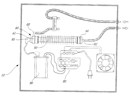
Fig 4 shows a water treatment system according to one embodiment of the
present invention. In this
embodiment the system is configured to be used for small scale water
treatment, for instance a
swimming pool or a hot tub. This water treatment system comprises ozone
generator means 120,
which generates ozone to be introduced into the water. The ozone generator 10,
shown in figure 2,
is suitable for such use. In this application it is usually sufficient to have
only a single ozone
generator. In use, water is taken out of the water holding tank (the pool or
tub, not shown) using
pump 130 which pumps the water through the system.
Ozone generated by the ozone generator means 120 is then introduced into the
water stream using a
venturi 140. The water then flows into a reaction chamber 150, which is
designed so as to allow the
ozone to have sufficient contact time with the pollutants in the water stream
so as to neutralize them.
As the water flows into the reaction chamber it preferably passes through a
diffuser (not shown)
which ensures that the ozone is better diffused in the water stream.
After the water has spent sufficient time in the water chamber, which can
either be a predetermined
time based on calculated time needed to reduce expected amount of pollutants,
or based on a reading
of any remaining pollutants in the water, the water may be filtered before
being moved on to an
ozone separator 160.
The ozone separator 160 separates any remaining gaseous ozone from the water
stream and sends
the gaseous ozone to a ozone eliminator 170 to be destroyed. The treated water
preferably still
containing dissolved ozone, is then returned to the pool or spa.
Fig 5 and 6, show cross sections of one detailed embodiment of the ozone
chamber 40 shown in fig
2. As can be seen in fig 5, the ozone chamber 40 is made up of end caps 42 and
44, an end fastening
means 46, glass tube 30, glass tube support means 32 and 34, ground electrode
50, and air tube
attachment means 61 and 63. As can be seen in fig 5, the ground electrode 50
has in this
embodiment cooling fins 52, which allow the ozone chamber 40 to be more easily
cooled.
17
CA 02385828 2002-05-10
Turning now to fig 6, we can see in greater detail the construction of the end
caps 42 and 44, as well
as the air flow within the ozone chamber 40.
Looking first at end cap 42, it can be seen that attached to an opening on the
side of the end cap 40
is attached air tube attachment means 61. Air tube attachment means 61 has
opening 60 through
which the source gas of the ozone generator may enter the ozone chamber 40.
Air tube attachment
61 is designed such that a source gas tube may easily be attached to it.
Also attached to end cap 42, is glass tube support means 32, which supports
one end of the glass
tube 30 within the ozone chamber 40. The glass tube support means also
contains a connector cable
36 which through which power is supplied to the first electrode 20. The glass
support means 32 is
attached to end cap 42 by means of end fastening means 46 such that the
attachment is air tight.
Looking now to end cap 44, it can be seen that end cap 44 also has an air tube
attachment means 63.
Air tube attachment means 63 has opening 62 through which ozone gas may exit
the ozone chamber
40. The air tube attachment means 63 is also design such that an air tube may
easily be attached to
it. End cap 44 also contains glass tube support means 34 which supports one
end of glass tube 30
within the ozone chamber 44.
Fig 6, also shows the path of a gas passing through the ozone chamber 40. This
path is indicated by
arrow 48. As can be seen the supply gas enters the chamber through opening 60
in air tube
attachment means 61, and is thereafter directed to the space 54 which exists
between glass tube 30
and ground electrode 50. In this space the supply gas is subjected to the
electrical discharge between
the first electrode 20 and the ground electrode, thus causing oxygen in the
gas to be turned into
ozone. This ozone then continues to the other end of the ozone chamber 40, and
exits through
opening 62 in air tube attachment means 63.
Figure 7, shows water treatment system according to one embodiment of the
invention. This water
treatment system is designed for use with a potable water supply and uses a
combination of ozone
and chlorine. Chlorine is used because ozone is unstable and will only last
for a short period of time.
Therefore if the water does not reach its end destination before the breakdown
time of the ozone the
18
CA 02385828 2002-05-10
water risks becoming polluted again if the aqueduct is defective, which is
often the case. Chlorine,
however, is very stable and can therefore be used to keep the water clean from
the time it leaves the
water treatment system until it reaches its end destination. If the water is
to be used closely, no
chlorine treatment is necessary.
In the water treatment system shown in fig 7, a water stream will enter
through entrance 200, and
will pass through a screen 205. The screen 205 removes larger particles which
can sometimes be
found in untreated water.
The water then passes from the screen 205 to a venturi 220 where the water is
injected with ozone
produced by ozone generator 230. In this embodiment of the water treatment
system, the ozone
generator 230 includes several additional mechanisms which increase its
efficiency. These are a
preliminary air treatment means 232 which cools and dries the air destined for
the ozone generator,
and an oxygen generator means 234 which takes the cooled and dried air and
separates the oxygen
from the other gasses which naturally occur in air. As a result a much larger
concentration of
oxygen is fed into the ozone generator 230, thus making the ozone generation
much more efficient
and less likely to breakdown.
Finally, the ozone generator 230 is fitted with a water cooling system 236
which cools the ozone
generator 230, and insures that it does not overheat again increasing its
efficiency.
After the water stream has been injected with ozone, the water flows into a
depressurized reaction
chamber 240, wherein it is stored until the ozone has had sufficient time to
react with the pollutants
in the water. The depressurized reaction chamber can also include an ozone
destroyer or vent 245
which removes any left over gaseous ozone from the chamber.
Finally, the water stream is passed through a sand filter 250 which removes
the oxidised pollutants
from the water stream. If required, the water stream is then injected with
chlorine from storage tanks
260 and 262, before being sent to its final destination 290.
Fig 8 shows another embodiment of the present invention, in which a complete
water treatment
19
CA 02385828 2002-05-10
system has been built into an easily transportable container. In this
embodiment the water treatment
system has been designed for compactness and ease of installation for a
client. This embodiment is
especially useful for large scale applications such as use as a small town's
main potable water
treatment facility. The reason for this is that large scale water treatment
systems for, for instance
municipal water treatment, often take up large amounts of space and require
the construction of a
building to house it.
Therefore, if the water treatment system was to be built on site, an even
larger area would be needed
and specialized workers would need to the present during the installation
period. This is especially
costly and inconvenient when the installation site is faraway. On the other
hand if a water treatment
system according to the present embodiment of the invention were to be used,
then the water
treatment system could be assembled and tested at a site distant from its
final location. The water
treatment system could then be easily transported to the final location and
would simply need to be
connected to the water network, and a suitable power supply.
As can be seen in fig 8, the water treatment system in the present embodiment
may be situated in a
standard container 300 (for example an 8 feet by 33 feet container). Water
enters through entrance
port 305 comprising a screen and passes through two filtration stages 310 and
312 in which larger
(20 microns or more) particles are first removed and then smaller (5 microns
or more) particles are
removed. The water can then either be passed through an ozonisation cycle or
just be cycled back
into the water network if no treatment is required.
In the embodiment shown in fig 8, water going through an ozonisation stage may
first be treated
with other chemicals, for instance chlorine to reduce the amount of pollutants
in the water before
being injected with ozone produced by ozone generator 330 using a venturi 320.
After being
injected with ozone, the water is stored in a reaction chamber 340 for
sufficient time to allow the
ozone to react with the pollutants in the water.
After the appropriate time has passed, the water is passed through filters 350
and 355 before being
sent into the water network 390.
CA 02385828 2002-05-10
The water treatment system of the embodiment shown in fig 8, additionally has
an electrical control
box 370 through with the water system can be controlled, and an entrance door
302 which allows
access to the water treatment system.
Fig 9, shows another e3nbodiment of a water treatment system 400 according to
the invention which
has been designed to be mobile and self contained. In this embodiment we can
see the flow of water
through the water treatment system 400. The water would enter the water
treatment system 400, at
point 405 and leave at point 480. As the water enters the water treatment
system 400, it first comes
to control station 475 where the water is treated with ozone produced by ozone
generators 430 and
432 and other chemicals as needed to maintain the pH balance of the water.
This embodiment of the invention contains ozone generators 430 and 432 which
are fitted with air
dehumidifier and cooler 437. The chemical products needed to maintain the pH
balance of the water
are stared in contained 435.
After being ozonated the water is allowed to pass to a reaction chamber 440,
containing a diffuser
445. The diffuser 445 works to diffuse the ozone in the water thereby
increasing efficiency of the
ozone. The water stays in the reaction chamber 440 for a time which is
sufficient to allow the ozone
to react with the pollutants in the water.
The water then passed to sand filters 452, 454, and 456 which work in parallel
to filter out the
ozonated pollutants of the water stream. The sand filters 452, 454, and 456
are also connected to
chlorine reservoir 460 such that chlorine may be used to make sure the filters
remain free of live
bacteria.
Finally, the water stream passes by chlorine pumps 465 and 467 which may
introduce chlorine in to
the water stream to insure that the treated water will not be recontaminated
when circulating in the
water distribution network.
In this embodiment of the invention the water treatment system also includes a
work post 4?7 at
which a human operator may monitor the system, and a control panel 470 for
controlling the system.
21
CA 02385828 2002-05-10
Fig 10, shows a possible housing for the embodiment of the water treatment
system shown in
figures 8 and 9.
As can be seen from the previous embodiments the water treatment system of the
present invention
using the new ozone generator shown in fig l, can easily be adapted to many
different uses.
Therefore, when designing a water treatment system it becomes important to
analyse the water
which is to be treated so that the water treatment system allows the treated
water to meet the
applicable standards and regulations.
When calculating the require size of the ozone generators for the water
treatment system to be
designed, there are primarily two factors which are the most important. These
factors are the
maximum water output, expressed in litres per minute or cubic metres per hour,
and the total
quantity of contaminants in the water.
To achieve a good result it then becomes necessary to have an ozone generator
which can produce at
least as much ozone which is necessary to clean the required amount of
contaminants out of the
required amount of water plus a safety factor.
In an example calculation for water commonly containing bacteria, iron, and
manganese
contaminants, lets say that bacteria require 0.8 mg of ozone per mg of
contaminant, iron requires 0.5
mg of ozone per mg contaminant, and manganese requires 1.0 mg of ozone per mg
of contaminant.
Prior testing, with different water condition can be used to establish how
much ozone is required to
oxidise a certain quantity of contaminants.
Now, suppose a water system needs at maximum 32 L/min of water, and said water
contains 1 mg/L
of iron, 0.5 mg/L of manganese, and 1 mg/L of bacteria. Thus the system
requires:
Ozone.per litre= (mg/L of bacteria)*0.8 + (mg/L of iron)* 0.5 + (mg/L of
manganese)* 1.0
- 0.8+0.5+0.5
- 1.8 mg/L
22
CA 02385828 2002-05-10
Thus the water treatment system would require an absolute minimum of : (32
L/min)*(1.8
mg/L)=57.6 mg/min= 3.456 g/h of ozone. Then the selected safety factor can be
applied.
As can be seen calculating the required amount ozone is quite simple after a
detailed analysis of the
amount of water required and the amount of pollutants per litre of water in
the original contaminated
source.
While the principles of this invention has been described in connection with
specific embodiments,
it should be understood clearly that these descriptions, along with the chosen
examples and data, are
made only by way of illustration and are not intended to limit the scope of
this invention, in any
manner. Various other ozonation systems and/or configurations can be used in
conjunction with the
invention. Many modifications and other embodiments of the invention will come
to the mind of
one skilled in the art having the benefit of the teachings presented in the
foregoing descriptions and
the associated drawings. No concerted attempt to repeat here what is generally
known to the artisan
has therefore been made. Therefore, it is to be understood that the invention
is not to be limited to
the specific embodiments disclosed, and that modifications and embodiments are
intended to be
included within the appended claims with the scope thereof determined by the
reasonable
equivalents, as understood by those skilled in the art.
23