Note: Descriptions are shown in the official language in which they were submitted.
CA 02386020 2004-12-21
TITLE
WALL STUD SPACER SYSTEM WITH
SPACER RETAINERS
BACKGROUND OF THE INVENTION
FIELD OF THE INVENTION
The subject invention relates to structures and, more particularly,
to walls constructed from metal studs and methods of constructing walls
utilizing metal studs.
-1-
CA 02386020 2002-05-10
DESCRIPTION OF THE INVENTION BACKGROUND
BACKGROUND OF THE INVENT:LON
Metal studs are commonly used today to form walls in
building structures. In a typical installation, the metal
studs are secured by screws at their lower ends to a bottom
track secured to a floor and at their upper ends to a top track
secured to overhead joists which may form the framework for an
upper floor. Wallboards or other panels are applied to the
sides of the studs to form a closed wall structure. A problem
with this arrangement is that deflection of the overhead joists
under loads is translated into vertical loads acting on the
studs. These vertical loads may cause bowing or other flexing
of the metal studs which. may cause the walls to crack or
otherwise be flawed or damaged.
Deflection track wall systems have been used in the past
to combat the problem of wall bowing and/or cracking arising
from overhead loads being applied to the vertical studs in a
non-load bearing wall. Three known deflection track wall
systems are commonly referred to as the crimped track system,
the double track system, and the track and brace system.
In the crimped stud system, the top track has a horizontal
crimp in each flange thereof. This permits relative vertical
movement between the upper and lower portions of each flange of
- 2 -
CA 02386020 2002-05-10
the top track. Accordingly, the metal studs can be fastened to
the lower portions of the flanges of the top track while the
crimps in the flanges accommodate vertical deflections of the
overhead structure to which the web of the top track-is .
secured.
In the double track system, two top tracks are nested one
within the other. The larger or upper track is attached to the
overhead joists or other overhead structure. The smaller or
lower track is nested within the larger rack and has attached
thereto the upper ends of the metal studs. There is a gap
between the webs of the two tracks that permits vertical
movement of the larger track without corresponding movement of
the smaller track.
The track and brace system uses a horizontal brace which
spans two or more metal studs. The brace extends through a
conduit hole in the web of each metal stud and is fastened to
an L-shape clip that in turn is fastened to the stud. The
brace eliminates the need to fasten the upper ends of the metal
studs to the top track which is then free to move vertically
2~ without imparting vertical loads in the metal studs.
The installation of. metal stud wall systems, including
deflection track wall systems, is generally a very time
consuming process. In a typical installation where the metal
studs are fastened at their upper ends to a top track or
- 3 -
CA 02386020 2002-05-10
channel, the attachment positions of the studs are marked off
along the top track. Then each stud is fastened to each flange
of the top track by screws. Often a ladder must be used
because the top track is too high for the installer to_reach. ,
The installer climbs the ladder. and fastens as many studs that
he can reach to the near_ flange of the top track. Then the
ladder must be moved to enable the installer to affix
additional studs to the top track. After doing this along one
side of the wall, the process is repeated on the other side of
the wall to fasten the studs to the other flange of the top
track. A similar process is used to install a track and brace
wall system, except that the fastening positions of the metal
studs are usually marked off along the brace. Also, only one
pass is needed to fasten the stud clips to the brace. Although
less time consuming in these respects, the time savings is more
than offset by the time expenditure or cost associated with
fastening the stud clips to the metal studs.
The stud wall spacers disclosed in U.S. Patent No.
5,784,850 to.Elderson and U.S. Patent No. 6,021,618 to Elderson
disclose stud wall spacers and methods that represent a vast
improvement over the above-mentioned approaches. When
utilizing the spacer members disclosed in those patents, it may
be advantageous to provide a means for further retaining the
spacer bars in position and to prevent their easy removal after
- 4 -
CA 02386020 2002-05-10
they have been installed. It may be further advantageous to
provide such a means that does not require the installer to
drill separate holes into the stud or to use other tools other
than the tools used to install the spacer. It may al-so be ,
advantageous to provide such a means that will operate
regardless of the vertical orientation of the stud.
SUMMARY OF THE INVENTION
In accordance with one embodiment of the present invention
there is provided a wall that includes at least two studs
wherein each stud has a web portion with an opening
therethrough. An elongated spacer member extends through the
opening in the webs of ai. least two studs. The spacer member
has at least one stud engager thereon that corresponds to each
web. The wall further includes at least one spacer retainer on
each web in retaining engagement with a corresponding stud
engager on the elongated spacer member.
Another embodiment of the present invention comprises a
wall that includes at least two studs wherein each stud has a
web portion with an opening therethrough. An elongated spacer
member extends through the opening in the webs of at least two
studs. The elongated spacer member has at least one stud
engager thereon that corresponds to each web for retaining
engagement therewith. fhe wall further includes at least one
- 5 -
CA 02386020 2002-05-10
spacer retainer formed on each web for retaining the spacer
member within the openings in the studs through which the
spacer member extends.
Another embodiment of the present invention comprises a .
wall that includes a bottom track and at least two structural
studs that each has a web with at least one opening
therethrough. Each opening has an upper end and a lower end
and the structural studs are affixed to the bottom track such
that at least one opening in the web of one structural stud is
in alignment with an opening in the web of another structural
stud. The wall also inc7_udes at least one elongated spacer
member that extends through the bottom end of at least two
aligned openings in the webs of the structural studs. Each
elongated spacer member has at least one notch formed therein
that corresponds to the web openings through which the
elongated spacer member extends. A dimple is provided on the
web of each stud and is oriented adjacent to the lower end of
the opening therein for retaining engagement with a
corresponding notch in the spacer member.
Another embodiment of the present invention comprises a
wall that includes a bottom track and at least two structural
studs that each has a web with at least one opening
therethrough. Each opening has an upper end and a lower end.
The structural studs are affixed to the bottom track such that
- 6 -
CA 02386020 2002-05-10
a least one opening in the web of one structural stud is in
alignment with an opening in the web of another structural
stud. At least one elongated spacer member extends through the
bottom end of at least two aligned openings in the we-'bs of the
structural studs. Each elongated spacer member has at least
one notch formed therein corresponding to the web openings
through which the elongated spacer member extends. A dimple is
provided on the web of each stud and is oriented adjacent to
the lower end of the opening therein for retaining engagement
with a corresponding notch in the spacer member.
Another embodiment of the present invention may comprise a
wall that includes at least two structural studs that each has
a web with at least one opening therethrough. Each opening has
two lateral sides. The structural studs are affixed to the
bottom track such that at least one opening in the web of one
structural stud is in alignment with an opening in the web of
another structural stud. At least one elongated spacer member
extends through the bottom end of at least two aligned openings
in the webs of the structural studs. Each elongated spacer
member has at least one notch formed therein corresponding to
the web openings through which the elongated spacer member
extends. The wall furf.her_ comprises an elongated dimple on
each web adjacent each lateral. side of the opening therein for
retaining engagement with a corresponding notch in the spacer
CA 02386020 2002-05-10
member.
Another embodiment of the present invention comprises a
method for constructing a wall which includes affixing at least
two studs each having a web portion with at least one opening ,
therethrough to a track such that at least one opening in the
web of one stud is aligned with an opening in at least one
other stud and inserting a spacer member through at least two
aligned openings. The method further includes engaging the
spacer member with corresponding spacer retainers on the webs
of the studs through which the spacer member extends.
Another embodiment of the present invention comprises a
method for constructing a wall which includes affixing the
lower end of a first stud to a track wherein the first stud has
a web with at Least one opening therethrough. The method
further includes affixing an upper end of a second stud to the
track such that an opening in a web of the second stud is in
alignment with the opening in the web of the first stud. In
addition, a spacer member is inserted through the aligned
openings in the first and second studs and the spacer member is
brought into engagement with corresponding spacer retainers on
each of the webs of the first and second studs.
Accordingly, the present invention further augments the
advantages provided when utilizing spacer members for spacing
and retaining studs in various construction settings and
- 8 -
CA 02386020 2002-05-10
applications. Those of ordinary skill in the art will readily
appreciate, however, that. these and other details, features and
advantages will become further apparent as the following
detailed description of the embodiments proceeds. w
BRIEF DESCRIPTION OF THE DRAWINGS
In the accompanying Figures, there are shown present
embodiments of the invention wherein like reference numerals
are employed to designate like parts and wherein:
FIG. 1 is a perspective view of a metal stud wall
employing a spacer member and studs of one embodiment of the
present invention;
FIG. 2 is a partial view of the spacer and one stud
depicted in Figure 1;
FIG. 3 is a perspective view of a stud spacer member;
FIG. 4 is a side view of a stud spacer member;
FIG. S is a perspective view of another spacer member;
FIG. 6 is a partial perspective view of the spacer member
and stud depicted in Figures 1 and 2;
FIG. 7 is a partial. view of the stud depicted in Figure 6;
FIG. 8 is a partial perspective view of a pair of
overlapping spacer members and a stud of the type depicted in
Figures 1 and 6;
FIG. 9 is a partial_ perspective view of a spacer member
- 9 -
CA 02386020 2002-05-10
and another drywall stud of the present invention;
FIG. 10 is a partial perspective view of a pair of
overlapping spacer members and the drywall stud depicted in
Figure 9; - ,
FIG. I1 is a partial. perspective view of a spacer member
and another drywall stud of the present invention;
Fig. 12 is a partial view of the stud of Figure 11;
FIG. 13 is a partial perspective view of a pair of
overlapping spacer members and the drywall stud depicted in
Figure 11;
FIG. 14 is a partial perspective view of a spacer member
and another drywall stud of the present invention;
FIG. 15 is a partial perspective view of a pair of
overlapping spacer members and the drywall stud of Figure 14;
FIG. 16 is a perspective view of another metal stud wall
employing another spacer member and other structural studs of
one embodiment of the present invention;
FIG. 17 is a partial perspective view of the spacer member
depicted in Figure 16;
FIG. 18 is a partial view of the spacer member and one
stud depicted in Figure 16;
FIG. 19 is a partial top view of the spacer member of
Figure 17;
FIG. 20 is a partial cross sectional view of the stud and
- 10 -
CA 02386020 2002-05-10
spacer member of Figure 18;
FIG. 21 is a side view of another spacer member of the
type depicted in Figure 17;
FIG. 22 is a partial perspective view of a spacer member ,
and a structural stud of the present invention;
FIG. 23 is a partial view of the stud of Figure 22;
FIG. 24 is a partial perspective view of a pair of
overlapping spacer members and the structural stud depicted in
Figure 22;
FIG. 25 is a partial. perspective view of a spacer member
and another structural stud of the present invention;
FIG. 26 is a partial_ perspective view of a pair of
overlapping spacer members and the structural stud depicted in
Figure 25;
FIG. 27 is a partia)_ perspective view of a spacer member
and another structural stud of the present invention;
FIG. 28 is a partial view of the stud of Figure 27;
FIG. 29 is a partial perspective view of a pair of
overlapping spacer members and the structural stud depicted in
Figure 28;
FIG. 30 is a partial perspective view of a spacer member
and another structural stud of the present invention;
FIG. 31 is a partial perspective view of a pair of
overlapping spacer members and the structural stud depicted in
- 11 -
CA 02386020 2002-05-10
Figure 30;
FIG. 32 is a partial perspective view of a spacer member
and another structural st=ud of the present invention;
FIG. 33 is a partial view of the stud of Figure-32;
FIG. 34 is a partial perspective view of a pair of
overlapping spacer members and the structural stud depicted in
Figure 32;
FIG. 35 is a partial perspective view of a spacer member
and another structural stud of the present invention;
FIG. 36 is a partial perspective view of a pair of
overlapping spacer members and the structural stud depicted in
Figure 35;
FIG. 37 is a partial perspective view of a spacer member
and another structural stud of the present invention;
FIG. 38 is a partial view of the stud of Figure 37;
FIG. 39 is a partial perspective view of a pair of
overlapping spacer members and the structural stud depicted in
Figure 37;
FIG. 40 is a partial perspective view of a spacer member
and another structural stud of the present invention; and
FIG. 41 is a partial perspective view of a pair of
overlapping spacer members and the structural stud depicted in
Figure 40.
- 12 -
CA 02386020 2002-05-10
DETAILED DESCRIPTION OF THE EMBODIMENTS OF THE INVENTION
Referring now to the drawings for the purposes of
illustrating the present preferred embodiments of the invention
only and not for the purposes of limiting the same, Figure 1 .
illustrates a metal stud wall "skeleton" 10 fabricated in
accordance with one embodiment of the present invention. In
this embodiment, the metal stud wall skeleton 10 includes a
lower track 12, a plurality of metal studs 20, and at least one
spacer member 40. Wall panels, such as wallboard, may be
secured in well-known manner to one or both sides of the metal
studs 20 to close the wall and. form the exterior surface or
surfaces of the wall. As the present Detailed Description
proceeds, those of ordinary skill in the art will appreciate
that the various embodiments of the present invention could be
successfully employed regardless of the orientation of the
wall.
In this embodiment, the studs 20 are generally C-shaped.
More particularly, the studs 20 have a web 22 and a pair of L-
shaped flanges 24 perpendicular to the web 22. There are also
one or more openings 26 in the web 22. Those of ordinary skill
in the art will appreciate that the openings 26 heretofore have
been provided in metal studs to permit electrical conduit and
plumbing to be run within the stud wall. Since the openings 26
are located in the same position in the individual studs
-- 13 -
CA 02386020 2002-05-10
forming the wail as is conventional, the openings 26 are
horizontally aligned with each other as shown in Figure 1.
In the assembly of the metal stud wall 10, the metal studs
20 are secured at one end 21 thereof to bottom track-12 by ,
conventional fasteners 23 such as, for example, screws, rivets,
etc. The bottom track 12 is also C-shaped with a central web
portion 14 and two legs 16 protruding therefrom. In
conventional construction situations, the web 14 of the bottom
track 12 is commonly affixed to the floor with conventional
fasteners such as screws, bolts, rivets, etc.
A stud spacer member 40 i.s inserted through the aligned
openings 26 provide through the webs 22 of the respective studs
such that the notches 42 in the stud spacer member 40 are
aligned with the web 22 of respective studs 20, or vice versa.
15 As will be discussed in further detail below, the stud spacer
member 40 also functions to maintain the metal studs 20 at the
prescribed spacing as during application of the wall panels to
the studs 20 thereby eliminating the need to secure the top or
another end 25 of each :stud 20 to an upper channel or header
20 (not shown). Although the wall panels once applied may
maintain the spacing of the metal studs as well, the stud
spacer member 40 may still function to assist in resisting
relative movement of the metal studs 20 in the plane of the
wall and to resist bowing of the studs 20. In addition, the
- 14 -
- CA 02386020 2004-12-21
stud spacer member also effectively prevents the torsional
rotation of the studs 20. In fact, additional spacer members
40 may be provided at different heights to add strength to the
metal stud wall skeleton 10.
One spacer member configuration is shown in Figures 3 and
4. As can be seen in those Figures, stud spacer member 40
comprises an elongated bar member 41 which is generally V-
shaped in cross-section along its length. The V-shape
functions to rigidify the elongated bar member 41 against
lateral flexure, i.e., flexure perpendicular to the
longitudinal axis of the stud spacer member. 40 and prevent the
torsional rotation of the studs. The V may have an included
angle in the range of about 45° to 135°, or about 60° to
120°
or about 90°.
The elongated member 41 need not necessarily be V-shaped
as shown in FIG. 3. The elongated member 41 alternatively
could be generally planar with one or more bosses running (and
overlapping if plural bosses are provided) the length of the
elongated member 41. The boss or bosses (deflected out of the
planar portions of the elongate member) would serve to rigidify
the elongated member 41. Of course, other means may be
provided to rigidify the elongate member 41 against lateral
flexure, such as the use of stiffening ribs, a thicker stock,
etc.
- 15 -
CA 02386020 2002-05-10
In the embodiment depicted in Figure 3, notches 42 are
provided in each planar side portion of the V-shaped elongated
member 41 with the notches 42 opening to the longitudinal outer
edge 44 of the respective side portion. The notches-42 have a
"stud engager" portion or "stud engagement means" for engaging
a portion of the web 22. In one embodiment, the stud engagers
or stud engagement means comprises a resiliently flexible tab
or flap 46 formed on one side of the notch 42 that functions to
resiliently bias the web 22 against an abutment 48 formed by
the opposite side of the notch 42. The flap 46 may be formed
by bending a portion of the respective side portion of
elongated member 41 out .of the plane of the side portion. The
opposite edge of the notch 42 preferably remains in the plane
of the relatively adjacent region of the side portion to form a
positive positioning stop or abutment 48 perpendicular to the
longitudinal axis of the elongated member 41 against which the
web 22 of the stud 20 will be held by the flexible flap 46.
The corners of the flap 46 at its free end may be relatively
sharply angled, as at an included angle of 60 degrees or less,
to form a barb for engaging a portion of the stud web.
Although the notches 42 are shown disposed along the outer
edge 44 of each side portion, it should be realized that the
notches 42 could be formed elsewhere, such as along the crease
49 of the V-shaped elongated member 41. However, in this
- 16 -
CA 02386020 2002-05-10
embodiment, the notches 42 open to the outer edge of each side
portion, with the notches 42 of one side portion being
laterally aligned with corresponding notches of the other side
portion. The pairs of laterally spaced notches 42, as opposed
to a single notch, provide two points of contact for the stud
spacer member 40. The two points of contact aid in preventing
the studs 20 from pivoting or twisting, thus adding greater
stability to the wall 10.
The stud spacer member 40 depicted in Figure 4 includes
four notches 42a-42d spaced at 16 inch (40.6cm) intervals, and
one notch 42e equally spaced between the two central notches
42b and 42c. This particular arrangement of notches 42 creates
a stud spacer member 40 which can be used in metal stud walls
10 which have a stud spacing of either 16 inches (40.6cm) or 29
inches (6lcm). If the wall 10 is to have a stud spacing of 16
inches (40.6cm), notches 42a-42d engage the webs 22 of the
studs 20. If the wall 10 is to have a stud spacing of 24
inches (6lcm), notches 42a, 42d, and 42e engage the webs 22 of
the studs 20. Those of ordinary skill in the art will of
course appreciate that the notches 42a-42e may be so oriented
to accommodate essentially any desired stud spacing
arrangement, for example:, wherein the webs 22 of the studs 20
are to be spaced at twelve inch (30.5cm) intervals.
The distance between abutments 48 will equate to a
- 17 -
CA 02386020 2004-12-21
distance between webs 22 of the studs 20 which form the
skeleton of the wall 10, as the flap 46 will force the web 22
against the abutment 48. As will be appreciated, the distance
between the cuts that form the abutments 48 and flaps 46 can be
controlled within relatively tight tolerances and this
translates to accurate spacing of the studs 20 in a row thereof
forming a wall. With one stud 20 plumbed and fixed in place,
all of the other studs 20 will be held plumb by the spacer
member 40 or chain of overlapping spacer members 40.
For example, in the United States, walls 10 are generally
constructed with studs spaced on 16 inch (40.6cm) or 24 inch
(6lcm) centers. Therefore, a cut in the elongate member 41
will be made at 16 (40.6cm) or 24 (6lcm) inch intervals, thus
ensuring that the web-to-web spacing of the studs 20 will be 16
inches (40.6cm) or 24 inches (6lcm).
In one embodiment, the overall length of a stud spacer
member 40 is about 50 inches (127cm). The spacer member 40 is
also sufficiently narrow so that it may be received in the
reduced width conduit slot forming the lower portion of the
stud opening as is often provided in the metal studs to
centrally space conduit between the outer side edges-of the
metal studs. The metal which forms the stud spacer member 40
may have a thickness ranging, for example, from about 22 gauge
to 16 gauge. In one embodiment, the stud
- 18 -
CA 02386020 2002-05-10
spacer member 40 is constructed from 16 gauge metal, which has
a thickness of .0538 inch (.165cm). In another embodiment, the
stud spacer member is fabricated from 20 gauge metal, which has
a thickness of about 0.0329 inch (.lcm). - ,
Another form of notch 42' has a slot portion 50 and a
relatively wider inner portion 52. See Figure 5. The slot
portion 50 extends from i~he enlarged inner portion 52 to the
outer longitudinal edge 44. The distinct transition from the
slot portion 50 to the enlarged inner portion 52 forms angled
shoulders 54 which "bite"' into the metal of the web 22 thereby
retaining the web 22 in the notch 42'. The slot portion 50 of
the notch 42' may have a width that corresponds to and may be
slightly less than the thickness of the metal forming the web
22, so that the slot portion 50 fits tightly over the web 22.
The enlarged inner portion 52 and the outer longitudinal edge
of the side portion 56 define therebetween a resilient flap
portion of the side portion that can flex away from opposed
flap portion to receive therebetween the web 22 of the stud 20.
The outer corners of the opposed flap portions are flared
slightly out of the plane of the side portion to form slightly
outturned ears 58 that define therebetween a widened mouth for
receiving and guiding the web 22 of the stud 20 into the
narrower through section of the slot portion 50.
The embodiment depicted in Figures 1, 2, and 6, includes
- 19 -
CA 02386020 2004-12-21
drywall studs 20 that have an opening 26 in the stud web 22
that has an upper portion 30 and a lower portion 32. The width
of the lower portion 32 (distance "A") is smaller than the
width of the upper portion 30 (distance "B"). The spacer
member 40 is sized to be received in the lower portion 32 of
the opening 26. In this embodiment, at least one and, as shown
in Figure 6, two "spacer retainers" or "spacer retaining means"
34 are provided in the portions of the web adjacent to the
points of intersection wherein the lower portion of the opening
meets the upper portion of the opening. In this embodiment, the
spacer retainers 34 are formed in the web and comprise
hemispherically shaped dimples 35. The dimples 35 may be
integrally formed in the web 22 of the stud 20 with
conventional metal forming processes and techniques, or they
may be otherwise attached to the web with appropriate
fasteners. For example, it is conceivable that the dimples 35
may be fabricated from metal and be welded, brazed, soldered,
etc. to the web 22 or attached with screws, etc. The dimples
35 could also conceivably be fabricated from other material
such as rubber, plastic, etc. and be attached to the web 22
with appropriate adhesive or other mechanical fasteners such as
screws or the like.
In this embodiment, the dimples 35 are sized and located
such that when the spacer bar member 40 is installed as shown
- 20 -
- CA 02386020 2004-12-21
in Figure 6, the ends of the flaps.46 of the spacer bar 40
engage or essentially "bite" into the dimples thereby retaining
the web 22 in the notch 42. In this embodiment, the notch 42
has a width which corresponds to and preferably is slightly
less than the thickness of the metal forming the web 22. In
addition, the dimples protrude a distance from the web 22
(distance "C" in Figure 7) and may have a diameter of
approximately 1/16-~ inches (.16-.63cm), so that the
corresponding flap 46 retainingly engages the dimple 35 to
retain the spacer bar 40 in retaining engagement with the web
22 of the stud 20. Those of ordinary skill in the art will
appreciate that, if desired, only one notch 42 which
corresponds to a particular stud 20 may be provided and
therefore the stud 20 may be provided with a single dimple 35
oriented for retaining engagement with the flap portion 46 of
the notch 42 when the spacer bar is seated within the lower
portion 32 of the opening 26. If desired, a pair of spacer
bars 40 may be overlapped as. shown in Figure 8. In that
embodiment, the dimples 35 are located for retaining engagement
with the flaps 46 of the uppermost spacer bar 40.
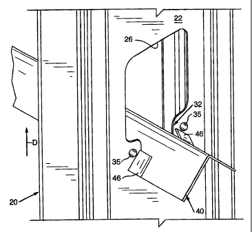
In the embodiment depicted in Figure 9, the dimples 35 are
oriented such that when the spacer bar 40 is installed as shown
(i.e., in seated engagement within the lower portion 32 of the
opening 26) the flaps 46 are not in engagement with the dimples
- 21 -
CA 02386020 2002-05-10
35, but instead engage portions of the web 22 beneath the
dimples 35. In this embodiment, the spacer bar 40 is moved
downwardly into the lower portion 32 of the opening, by tapping
the spacer bar 40 into position. The width of the notch 42
must be sufficient to permit the flaps 46 to be biased over the
dimples 35 when the bar 40 is being installed. Once installed
in the position as shown in Figure 9, the dimples 35 would
retard the inadvertent upward movement (direction represented
by arrow "D") to prevent the removal of the spacer bar 40 from
the stud 20.
Figure 10 depicts the use of two overlapped spacer bars
40. In that embodiment, the dimples 35 are located relative to
the flaps 46 of the uppermost spacer bar 40 such that the flaps
46 do not engage the dimples 35, but the dimples 35 would
prevent easy detachment of the spacer bars 40 from the web 22
of the stud 20.
Another embodiment of the present invention is depicted in
Figures 11 and 12. As can be seen in Figure 11, this
embodiment includes at least one stud 120 that is essentially
identical in construction when compared to studs 20 above,
except for the spacer retainers 135. In particular, this stud
120 has-a web 122, two L-shaped legs 124, at least one opening
126 through the web 122 .and at least one and preferably two
spacer retainers 134 in the form of dimples 135 provided in the
- 22 -
CA 02386020 2002-05-10
shape of a quarter sphere. In this embodiment, the dimples 135
are sized and located such that when the spacer bar member 40
is installed as shown in Figure 11, the ends of the flaps 46 of
the spacer bar 40 engage or essentially "bite" into the dimples
135 thereby retaining the web 122 in the notch 42. In this
embodiment, the notch 42 has a width which corresponds to and
preferably is slightly less than the thickness of the metal
forming the web 122. In addition, the dimples 135 protrude a
distance from the web 122 (distance "E" in Figure 12), so that
the corresponding flap 46 retainingly engages the dimple 135 to
retain the spacer bar 40 in retaining engagement with the web
122 of the~stud 120. Those of ordinary skill in the art will
appreciate that, if desired, only one notch 42 which
corresponds to a particu:Lar stud 120 may be provided and
therefore the stud 120 may be provided with a single dimple 135
oriented for retaining engagement with the flap portion 46 of
the notch 42 when the spacer bar 40 is seated within the lower
portion 132 of the opening 126. If desired, a pair of spacer
bars 40 may be overlapped as shown in Figure 13. In that
embodiment, the dimples 135 are located for retaining
engagement with the flaps 46 of the uppermost spacer bar 40.
In the embodiment depicted in Figure 14, the dimples 135
are oriented such that when the spacer bar 40 is installed as
shown (i.e., in seated engagement within the lower portion 132
- 23 -
. - CA 02386020 2004-12-21
of the opening 126) the flaps 46 are not in engagement with the
dimples 135, but instead engage portions of the web 122 beneath
the dimples 135. In this embodiment, the spacer bar 40 is
moved downwardly into the lower portion 132 of the opening, by
tapping the spacer bar 40 into position. The width of the
notch 42 must be sufficient to permit the flaps 46 to be biased
over the dimples 135 when the bar 40 is being installed. Once
installed in the position as shown in Figure 14, the dimples
135 would retard the inadvertent upward movement (direction
represented by arrow "D") to prevent the removal of the spacer
bar 40 from the stud 120.
Figure 15 depicts the use of two overlapped spacer bars
40. In that embodiment, the dimples 135 are located relative
to the flaps 46 of the uppermost spacer bar 40 such that the
flaps 46 do not engage the dimples 135, but the dimples 135
would prevent easy detachment of the spacer bars 40 from the
web 122 of the stud 120.
Figures 16-23 illustrate yet another embodiment of the
present invention wherein structural studs 220 and spacer bars
140 are employed. In this embodiment, each planar side portion
of the V-shaped elongated member 141 is provided with a
plurality of notches 142 which open to the longitudinal or
laterally outer edge 144 of the respective side portion. The
notches 142 may be formed to a depth from the edge of about
- 24 -
CA 02386020 2002-05-10
three-eighths of an inch (about 0.95 cm). Although the notches
142 are shown disposed along the outer edge 144 of each side
portion, the notches 142 could be formed elsewhere, although
less desirably, such as along the vertex (crease) of -the
V-shape elongated member 141.
The notches 142 of one side portion are laterally aligned
with corresponding notches of the other side portion. The
pairs of laterally alignE:d notches 142, as opposed to a single
notch, provide two areas of contact with the web 222 of a stud
220. See Fig. 20. The two areas of contact may enhance the
grip of the bridging/spacing member 140 on the webs 222 of the
studs 220 and aid in pre~Jenting the studs 220 from pivoting or
twisting, thus adding greater stability to the wall.
Referring now to Figs. 17, 19' and 20, each notch 142 may
be formed by a slot 150 inclined relative to the longitudinal
axis of the stud bridgin~g/spacing member 140, wherein the angle
and the width of the slot 150 cooperate to bind the webs 222 of
the studs 220 in the notches 142. The slot 150 may have a
width of about 0.065 inch (about 0.16 cm) to about 0.080 inch
(about 0.20 cm), and may be angled about five and a half
degrees to about eight degrees relative to a perpendicular to
the longitudinal axis of the bridging/spacing member 140. More
preferably, the slot 150 is angled about seven degrees and has
a width of about 0.080 inch (about 0.20 cm). The slot 150
- 25 -
.. ' CA 02386020 2004-12-21
generally has parallel sides that are straight. However, other
configurations are contemplated. For example, the slot 150 may
have curved parallel sides.
The stud bridging/spacing member 140 may be made of
eighteen to fourteen gauge metal. In one embodiment for
example, the stud bridging/spacing member is made from 16 gauge
.0538 inch (.165cm) and another embodiment is fabricated from
20 gauge .0329 inch (.lcm). The width and angle provide
notches 142 which have been found to fit twenty gauge studs
220, to fit eighteen gauge studs 220 with a slight bind, and to
fit sixteen gauge studs 220 tightly, which may cause the webs
222 of the studs 220 to bend slightly with the notch 142. The
notches 142 have also been found to fit fourteen gauge studs
220, with a tight fit. The tighter fit with heavier gauge
i5 studs is desired as usually they are used to bear higher loads.
As shown in Fig. 19, the sides of the angled notch 142
form angled shoulders in adjacent portions of the elongated
member 141, one of which forms an abutment 152 against which
the web 222 of the stud 220 is urged, and the other of which
forms a "stud engager" or "stud engagement means" in the form
of a barb 154 which can "bite" into the web 222 of the stud 220
and about which the web 222 of the stud 220 may deform as the
web 222 is inserted into the notch 142. The angle and the
width of the slot 150 cooperate to bind the web 222 of the stud
- 26 -
CA 02386020 2002-05-10
220 in the slot 150. At least when subjected to loads that
would tend to cause the elongated member to become dislodged.
The bind forces a portion of the web 222 to bend with the angle
of the slot 150. However, generally neither the barb 154 nor
the abutment 152 move out of the plane of the planar portion of
the elongated member 141.
As illustrated in Fig. 21, the stud bridging/spacing
member 140 includes four notches 142a-142d spaced at sixteen
inch (about 40.6 cm) intervals, and one notch 142e equally
spaced between the two central notches 142b and 142c. This
particular arrangement of notches 142 creates a stud;
bridging/spacing member 140 which can be used in metal stud
walls which have a stud spacing of either sixteen or twenty-
four inches (about 40.6 cm to 61.0 cm). If the wall is to have
a stud spacing of sixteen inches (about 90.6 cm), notches 142a-
142d engage the webs 122 of the studs 120. If the wall is to
have a stud spacing of twenty-four inches (about 61.0 cm),
notches 142a, 142d, and 142e engage the webs 122 of the studs
120. Since the overall length of the stud bridging/spacing
member 140 in this embodiment is about fifty inches (about 127
cm), this leaves about one inch (about 2.5 cm) outside the
outermost notches. Those of ordinary skill in the art will
appreciate that notches 142a-142d may be arranged at a variety
of intervals depending upon the desired stud spacing. For
- 27 -
CA 02386020 2004-12-21
example, the notches 142a-142d may be so located to support
studs spaced at twelve inch (about 30.5 cm) intervals.
As can be seen in Figure 16, in this embodiment, the
spacer member 140 is used in connection with structural studs
S 220 in the manner described above with respect to drywall
studs. However, the structural studs 220 have an oval shaped
opening 226 in their webs 222. More particularly, a stud 220
has a web 222, two L-shaped legs 224, at least one opening 226
through the web 222 and at least one and preferably two spacer
retainers 234. The opening 226 may have a lower portion 227
and an upper portion 228 and two lateral side portions 229. As
can be further seen in Figure 22, the spacer member 140 is
inserted through the opening 226 such that it is received in
the bottom portion of the opening 226. The spacer retainers
234 comprise hemispherically shaped dimples 235 formed adjacent
the lower end 227 of the opening 226. In this embodiment, the
dimples 235 are sized and located such that when the spacer bar
member 140 is installed as shown in Figure 21, the barb 154 of
the spacer bar 140 engage or essentially "bite" into the
dimples 135 thereby retaining the web 222 in the notch 142. In
this embodiment, the notch I42 has a width which corresponds to
and preferably is slightly less than the thickness of the metal
forming the web 222. In addition, the dimples 235 protrude a
distance from the web 222 (distance "F" in Figure 23), so that
- 28 -
CA 02386020 2002-05-10
the corresponding barb 154 retainingly engages the dimple 235
to retain the spacer bar 140 in retaining engagement with the
web 222 of the stud 220. However other notch configurations
and widths could conceivably be used.
Those of ordinary skill in the art will appreciate that
the studs 220 may be fabricated such that they are symmetrical.
When constructed in that manner, either end of a stud may be
attached to the bottom track 12. In particular, as shown in
Figure 16, the end 221 of each stud 220 is attached to the
bottom track 12. However, in the alternative, the ends 225 may
be attached to the bottom track 12. Such stud construction
eliminates the need to determine which end of the stud is to be
attached to the bottom track and serves to speed up
installation. Accordingly, to accommodate retention of the
spacer bar 190 regardless of which end of the stud 220 is
affixed to the bottom track 12, a second pair 240 of spacer
retainers 234 or at least a third spacer retainer 234 is
provided adjacent to the other end of the opening 226 as shown
in Figures 16 and 22. The spacer retainers 234 in that
embodiment may be identical to the dimples 235 described above.
This feature eliminate~> the need for the installer to always
ensure that the same ends of the studs 20 are always affixed
to, for example, the bottom track 12.
Figure 24 depicts t:he use of two overlapped spacer bars
- 29 -
CA 02386020 2004-12-21
140. In that embodiment, the dimples 235 are located relative
to the barbs 154 of the uppermost spacer bar 140 such that the
barbs 154 engage the dimples 235 to prevent the torsional
rotation of the studs 220 when the spacer bars have been
installed. In addition, the dimples prevent one end of the
spacer bar from becoming disengaged while the installer engages
the other end of the spacer bar with a corresponding stud or
studs.
In the embodiment depicted in Figure 25, the dimples 235
are oriented such that when the spacer bar 140 is installed as
shown (i.e., in seated engagement within the lower portion of
the opening 226) the barbs 154 are not ~in engagement with the
dimples 235, but instead engage portions of the web 222 beneath
the dimples 235. In this embodiment, the spacer bar 140 is
moved downwardly into the lower portion of the opening 226, by
tapping the spacer bar 140 into position. The width of the
notch 142 must be sufficient to permit the bar to be biased
over the dimples 235 when the bar 140 is being installed. Once
installed in the position as shown in Figure 25, the dimples
235 would retard the inadvertent upward movement (direction
represented by arrow "D") to prevent the removal of the spacer
bar 140 from the stud 220. As can also be seen in Figures 24
and 25, a second pair 240' of spacer retainers in the form of
dimples 235' may be provided adjacent the other end of the
- 30 -
CA 02386020 2002-05-10
opening 226. Those of ordinary skill in the art will readily
appreciate that the pair of spacer retainers 240' eliminate the
need for the studs to be installed with a certain one of their
respective ends always attached to, for example, the-upper or
lower header.
Figure 26 depicts the use of two overlapped spacer bars
140. In that embodiment, the dimples 235 are located relative
to the barbs 154 of the uppermost spacer bar 140 such that the
barbs 154 do not engage the dimples 235, but the dimples 235
would prevent easy detachment of the spacer bars 140 from the
web 222 of the stud 220.
Another embodiment of the present invention is depicted in
Figures 27 and 28. As can be seen in Figure 27, this
embodiment includes at least one stud 320 that is essentially
identical in construction when compared to studs 220 above,
except for the spacer retainers 334. In particular, this stud
320 has a web 322, two L-shaped legs 324, at least one opening
326 through the web 322. and at least one and preferably two
spacer retainers 334 in the form of dimples 335 provided in the
shape of a quarter sphere. In this embodiment, the dimples 335
are sized and located such that when the spacer bar member 140
is installed as shown in Figure 27, the barbs 154 of the spacer
bar 40 engage or essentially "bite" into the dimples 335
thereby retaining the web 322 in the notch 142. In this
- 31 -
. CA 02386020 2004-12-21
embodiment, the notch 142 has a width which corresponds to and
preferably is slightly less than the thickness of the metal
forming the web 322. In addition, the dimples 335 protrude a
distance from the web 122 (distance "G" in Figure 28), so that
the corresponding barb 154 retainingly engages the dimple 335
to retain the spacer bar 140 in retaining engagement with the
web 322 of the stud 320. Those of ordinary skill in the art
will appreciate that, if desired, only one notch 142 which
corresponds to a particular stud 320 may be provided and
l0 therefore the stud 320 may be provided with a single dimple 335
oriented for retaining engagement with the barb portion 154 of
the notch 142 when the spacer bar 140 is seated within the
lower portion of the opening 326. As can also be seen in
Figure 27, a second pair 340' of spacer retainers in the form
of dimples 335' may be provided adjacent the other end of the
opening 326. If desired, a pair. of spacer bars 140 may be
overlapped as shown in Figure 29. In that embodiment, the
dimples 335 are located for retaining engagement with the barbs
154 of the uppermost spacer bar 140.
In the embodiment depicted in Figure 30, the stud 420 is
identical in construction when compared to stud 320. In
particular, stud 420 has a web 422 that has an opening 426
therethrough. At least one spacer retainer 434, and preferably
- 32 -
CA 02386020 2002-05-10
two spacer retainers 434 in the form of dimples 435 in the
shape of a quarter spherE~ are oriented such that when the
spacer bar 140 is installed as shown (i.e., in seated
engagement within the lower portion of the opening 426) the
barbs 154 are not in engagement with the dimples 435, but
instead engage portions of the web 422. beneath the dimples 435.
In this embodiment, the spacer bar 140 is moved downwardly
into the lower portion of the opening 426, by tapping the
spacer bar 140 into position. The width of the notch 142 must
be sufficient to permit the bar to be biased over the dimples
435 when the bar 140 is being installed. Once installed in the
position as shown in Figure 30, the dimples 435 would retard
the inadvertent upward movement (direction represented by arrow
"D") to prevent the removal of the spacer bar 140 from the stud
420. Also, a second pair 940' of spacer retainers 434' in the
form of dimples 435' in the shape of a quarter sphere may be
provided adjacent the other end of the opening 426 as shown in
Figure 30. The dimples 435, 435' may be integrally formed in
the web 422 or otherwise attached thereto by the various
methods and mediums described above. In addition, dimples 435,
435' may protrude the same distance from the web 422 as the
dimples 335, 335' protrude from web 322 as described above.
Figure 31 depicts the use of two overlapped spacer bars
140. In that embodiment., the dimples 435 are located relative
- 33 -
CA 02386020 2002-05-10
to the barbs 154 of the uppermost spacer bar 140 such that the
barbs 154 do not engage the dimples 435, but the dimples 435
would prevent easy detachment of the spacer bars 140 from the
web 422 of the stud 420.
Another embodiment of the present invention is depicted in
Figures 32 and 33. As can be seen in Figure 32, this
embodiment includes at least one stud 520 that is essentially
identical in construction when compared to studs 420 above,
except for the arrangement of spacer retainers 534, 534'. In
particular, this stud 520 has a web 522, two L-shaped legs 524,
at least one opening 526 through the web 522 and at least one
and preferably two series 533 of stacked spacer retainers 539
in the form of dimples 535 provided in the shape of a quarter
sphere. In this embodiment, a series of nine dimples 535 are
sized and located along t:he sides of the opening 526 adjacent
one end thereof such that when the spacer bar member 140 is
installed as shown in Figure 32, the barbs 154 of the spacer
bar 140 engage or essentially "bite" into at least one of the
dimples 535 thereby retaining the web 522 in the notch 142. In
this embodiment, the notch 142 has a width which corresponds to
and preferably is slight:Ly less than the thickness of the metal
forming the web 522. In addition, the dimples 535 protrude a
distance from the web 52:? (distance "H" in Figure 33), so that
the corresponding barb 154 retainingly engages the dimple 535
- 34 -
CA 02386020 2002-05-10
to retain the spacer bar 140 in retaining engagement with the
web 522 of the stud 520. However other notch configurations
and widths could conceivably be used. Those of ordinary skill
in the art will appreciate that, if desired, only one notch 142
which corresponds to a particular stud 520 may be provided and
therefore the stud 520 may be provided with a single series 533
of stacked dimples 535 oriented for retaining engagement with
the barb portion 154 of the notch 142 when the spacer bar 140
is seated within the lower portion of the opening 526. As can
also be seen in Figure 32, a second series 533' of stacked
spacer retainers 534' in the form of dimples 535' may be
provided adjacent the other end of the opening 536 on each side
thereof. As used herein, the term "series" refers to at least
two stacked spacer retainers. As with the above-described
embodiments, the spacer retainers 534, 534' may be integrally
formed from the web 522 or otherwise formed from a separate
material of the types described above and otherwise attached to
the web 522 of the stud 520 by the various methods described
above.
If desired, a pair of spacer bars 140 may be overlapped as
shown in Figure 34. In that embodiment, the series 533 of
stacked dimples 535 may be located for retaining engagement
with the barbs 154 of both of the spacer bars 140.
In the embodiment depicted in Figure 35, the stud 620 is
- 35 -
CA 02386020 2002-05-10
identical in construction when compared to stud 520. In
particular, stud 620 has a web 622 that has an opening 626
therethrough and at least one and preferably two series 633 of
stacked spacer retainers 634 in the form of dimples 635
provided in the shape of a quarter sphere. The dimples 635 are
oriented such that when the spacer bar 140 is installed as
shown (i.e., in seated engagement within the lower portion of
the opening 626) the barbs 154 are not in engagement with the
dimples 635, but instead engage portions of the web 622 beneath
the dimples 635. In this embodiment, the spacer bar 140 is
moved downwardly into the lower portion of the opening 626, by
tapping the spacer bar 190 into position. The width of the
notch 142 must be sufficient to permit the bar to be biased
over the dimples 635 when the bar 140 is being installed. Once
installed in the position as shown in Figure 35, the dimples
635 would retard the inadvertent upward movement (direction
represented by arrow "D") to prevent the removal of the spacer
bar 140 from the stud 620. Also, a second series 633' of
stacked spacer retainers 634' in the form of dimples 635' may
be provided on each side of the other end of the opening 626 as
shown. The dimples 635, 635' may be integrally-formed in the
web 622 or otherwise attached thereto by the various methods
and mediums described above. In addition, dimples 635, 635'
may protrude the same diatance from the web 622 as the dimples
- 36 -
CA 02386020 2002-05-10
535, 535' protrude from web 522 as described above.
Figure 36 depicts the use of two overlapped spacer bars
140. In that embodiment, the dimples 635 are located relative
to the barbs 154 of the uppermost spacer bar 140 such that the ,
barbs 154 do not engage t:he dimples 635, but the dimples 635
would prevent easy detachment of the spacer bars 140 from the
web 622 of the stud 620.
Another embodiment of the present invention is depicted in
Figures~37 and 38. As can be seen in Figure 37, this
embodiment includes at least one stud 720 that is essentially
identical in construction when compared to studs 620 above,
except for the spacer retainers 734. In particular, this stud
720 has a web 722, two L~-shaped legs 724, at least one
elongated opening 726 through the web 722 that has a length
designated as "K". At least one and preferably two elongated
continuous spacer retainers 734 are oriented adjacent the sides
of the opening 726. In this embodiment, the spacer retainers
734 have the shape of a quarter sphere and have a series of
serrations 737. Also in this embodiment, the length "I" of the
spacer retainers is greater than the length "K" of the opening
726 such that a portion of the spacer retainers 734 protrude
beyond the ends of the opening 726 as shown. For example, for
an opening that is 4 inches (10.16cm) long, the spacer
retainers 734 may be 6 inches (15.24cm) long. However, other
- 37 -
CA 02386020 2002-05-10
lengths and arrangements could be easily employed. Those of
ordinary skill in the art. will recognize that the spacer
retainers 734 need only Extend far enough beyond the ends of
the opening to engage the spacer bar. The spacer retainers 734 ,
are oriented such that when the spacer bar member 140 is
installed as shown in Figure 37, the barbs 154 of the spacer
bar 140 engage or essentially "bite" into at least one of the
spacer retainers 734 thereby retaining the web 722 in the notch
142. In this embodiment, the notch 142 has a width which
corresponds to and preferably is slightly less than the
thickness of the metal forming the web 722. In addition, the
spacer retainers 734 protrude a distance from the web 722
(distance "J" in Figure 38), so that the corresponding barb 154
retainingly engages the spacer retainer 734 to retain the
spacer bar 140 in retaining engagement with the web 722 of the
stud 720. Those of ordinary skill in the art will appreciate
that, if desired, only one notch 142 which corresponds to a
particular stud 720 may be provided and therefore the stud 720
may be provided with a single spacer retainer 734 oriented for
retaining engagement with the barb portion 154 of the notch 142
when the spacer bar 140 is seated within an end portion of the
opening 726. As shown in Figures 37 and 38, a plurality of
serrations may be provided in the spacer retainers 734. In the
alternative, however, the spacer retainers may be formed
- 38 -
CA 02386020 2004-12-21
without such serrations if so desired. As with the above-described
embodiments, the spacer retainers 734 may be integrally formed from
the web 722 or otherwise formed from a separate material of the
types described above and otherwise attached to the web 722 of the
stud 720 by the various methods described above.
If desired, a pair of spacer bars 140 may be overlapped as
shown in Figure 39. In that embodiment, the spacer retainers 734
may be located for retaining engagement with the barbs 154 of both
of the spacer bars 140.
In the embodiment depicted in Figure 40, the stud 820 is
identical in construction when compared to stud 720. In particular,
stud 820 has a web 822 and a pair of legs 824. Web 822 has an
opening 826 therethrough and at least one and preferably two spacer
retainers 834 in the form of elongated dimples 835 provided in the
shape of a quarter sphere. The dimples 835 may have serrations 837
therein and are oriented such that when the spacer bar 140 is
installed as shown (i.e., in seated engagement within the lower
portion of the opening 826) the barbs 154 are not in engagement with
the spacer retainers 834, but instead engage portions of the web 822
beneath the spacer retainers 834. In this embodiment, the spacer
bar 140 is moved downwardly into the lower portion of the opening
826, by tapping the spacer bar 140 into position. The width of the
- 39 -
CA 02386020 2002-05-10
notch 142 must be sufficient to permit the bar to be biased
over the spacer retainers 834 when the bar 140 is being
installed. Once installed in the position as shown in Figure
40, the spacer retainers 834 would retard the inadvertent
upward movement (direction represented by arrow "D") to prevent
the removal of the spacer bar 140 from the stud 820. The
elongated dimples 835 may be integrally formed in the web 822
or otherwise attached thereto by the various methods and
mediums described above. In addition, dimples 835 protrude the
same distance from the web 822 as the dimples 735 protrude from
web 722 as described above.
If desired, a pair of spacer bars 140 may be overlapped as
shown in Figure 41. In that embodiment, the spacer retainers
834 may be located for retaining engagement with the barbs 154
of both of the spacer bars 140.
Although the invention has been shown and described with
respect to several embodiments, it will be apparent that
equivalent alterations and modifications will occur to others
skilled in the art upon t:he reading and understanding of this
specification. The present invention includes all such
equivalent alterations and modifications, and is limited only
by the scope of the following claims.
- 40 -