Language selection

Search

Patent 2386280 Summary

Third-party information liability

Some of the information on this Web page has been provided by external sources. The Government of Canada is not responsible for the accuracy, reliability or currency of the information supplied by external sources. Users wishing to rely upon this information should consult directly with the source of the information. Content provided by external sources is not subject to official languages, privacy and accessibility requirements.

Claims and Abstract availability

Any discrepancies in the text and image of the Claims and Abstract are due to differing posting times. Text of the Claims and Abstract are posted:

  • At the time the application is open to public inspection;
  • At the time of issue of the patent (grant).
(12) Patent: (11) CA 2386280
(54) English Title: SWEEPER MAGNET
(54) French Title: AIMANT A BALAYAGE
Status: Expired and beyond the Period of Reversal
Bibliographic Data
(51) International Patent Classification (IPC):
  • B3C 1/02 (2006.01)
  • A47L 13/41 (2006.01)
(72) Inventors :
  • OTTENS, COREY J. (United States of America)
(73) Owners :
  • NATIONAL MANUFACTURING COMPANY
(71) Applicants :
  • NATIONAL MANUFACTURING COMPANY (United States of America)
(74) Agent: FINLAYSON & SINGLEHURST
(74) Associate agent:
(45) Issued: 2009-08-11
(22) Filed Date: 2002-05-15
(41) Open to Public Inspection: 2003-11-08
Examination requested: 2007-02-07
Availability of licence: N/A
Dedicated to the Public: N/A
(25) Language of filing: English

Patent Cooperation Treaty (PCT): No

(30) Application Priority Data:
Application No. Country/Territory Date
10/140,160 (United States of America) 2002-05-08

Abstracts

English Abstract

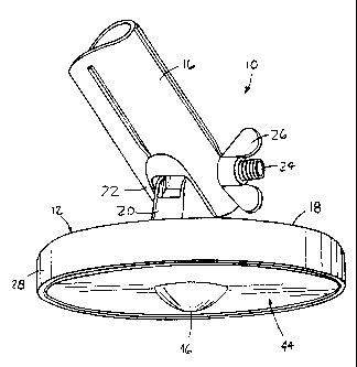
A sweeper magnet for attracting magnetic debris from a pick-up surface includes a base assembly and a magnet having a first surface supported by the base assembly and a second surface. A cover extends over the magnet second surface and includes a projection having a projection height extending away from the magnet. The projection automatically creates a space distance of at least the projection height between the pick-up surface and at least a portion of the cover to provide clearance for attracting the magnetic debris


French Abstract

Un aimant à balayage permettant de recueillir des débris magnétiques présents sur une surface comprend une base et un aimant à deux faces, l'une étant couverte par la base et l'autre, apparente. Un couvercle recouvre cette seconde surface et comporte une saillie. Cette saillie crée automatiquement un espace minimal égale à au moins sa hauteur entre la surface et une partie au moins du couvercle afin d'attirer les débris magnétiques.

Claims

Note: Claims are shown in the official language in which they were submitted.


What is Claimed is:
1. A sweeper magnet for attracting magnetic debris from a pick-up surface,
the sweeper magnet comprising:
a base assembly;
a magnet having a first surface supported by the base assembly and a second
surface; and
a unitary cover extending over at least a portion of the magnet second
surface, the cover including a projection having a projection height extending
away from the magnet;
wherein the projection automatically creates a space distance of at least the
projection height between the pick-up surface and at least a portion of the
cover to
provide clearance for attracting the magnetic debris.
2. The sweeper magnet of claim 1, in which the projection extends from a
central portion of the cover and the cover includes a substantially planar
portion
surrounding the projection.
3. The sweeper magnet of claim 2, in which the cover includes a transition
area between the cover planar portion and the cover projection.
4. The sweeper magnet of claim 3, in which the transition area is formed with
a radius.
5. The sweeper magnet of claim 4, in which the transition area radius is equal
to approximately 0.1 inches.
6. The sweeper magnet of claim 1, in which the cover comprises a
ferromagnetic material, and in which the magnet secures the cover in place.
7. The sweeper magnet of claim 1, in which the base assembly includes a base
supporting the magnet and a coupling pivotably attached to the base.
-5-

8. The sweeper magnet of claim 7, in which the coupling includes a threaded
end.
9. The sweeper magnet of claim 1, further comprising a mounting cup having
a magnet recess sized to receive the magnet, wherein the magnet is secured to
the
mounting cup and the mounting cup is secured to the base assembly.
10. The sweeper magnet of claim 1, in which the projection comprises a
bubble.
11. The sweeper magnet of claim 1, in which the bubble is formed along a
radius of approximately 0.5 inches.
12. The sweeper magnet of claim 1, in which the projection height is equal to
approximately 0.25 inches.
13. A sweeper magnet for attracting magnetic debris from a pick-up surface,
the sweeper magnet comprising:
a base assembly including a base having a cylindrical side wall depending
from a top wall to define a cup recess, and a coupling pivotably attached to
the base;
a mounting cup sized for insertion into the base cup recess and attached to
the
base, the mounting cup defining a magnet recess;
an annular magnet sized for insertion into the mounting cup magnet recess, the
magnet including a first surface attached to the mounting cup and a second
surface;
and
a unitary cover sized to extend over at least a portion of the magnet
second surface, the cover including a projection having a projection height
extending away from the magnet;
wherein the projection automatically creates a space distance of at least the
projection height between the pick-up surface and at least a portion of the
cover to
provide clearance for attracting the magnetic debris.
-6-

14. The sweeper magnet of claim 13, in which the projection extends from a
central portion of the cover and the cover includes a substantially planar
portion
surrounding the projection.
15. The sweeper magnet of claim 14, in which the cover includes a transition
area between the cover planar portion and the cover projection.
16. The sweeper magnet of claim 15, in which the transition area is formed
with a radius.
17. The sweeper magnet of claim 16, in which the transition area radius is
equal to approximately 0.1 inches.
18. The sweeper magnet of claim 13, in which the cover comprises a
ferromagnetic material, and in which the magnet secures the cover in place.
19. The sweeper magnet of claim 13, in which the projection comprises a
bubble.
20. The sweeper magnet of claim 13, in which the projection height is equal
to approximately 0.25 inches.
-7-

Description

Note: Descriptions are shown in the official language in which they were submitted.


CA 02386280 2007-03-05
SWEEPER MAGNET
Field of the Invention
The present invention generally relates to pick-up tools and, more
particularly,
to sweeper magnets.
Background of the Invention
Conventional sweeper magnets typically include a magnet assembly attached
to an elongate handle. The magnet assembly includes a base adapted for
attachment
to the handle and a magnet attached to the base. During use, the magnetic
sweeper is
positioned in sufficient proximity to a pick-up surface so that the magnet
attracts
magnetic debris on the surface. The magnetic debris is pulled to the surface
of the
magnet or a magnet cover plate, and is subsequently removed, often manually.
Such conventional magnetic sweepers are overly difficult and cumbersome to
use. Care must be taken to insure that the magnet assembly is spaced a proper
distance from the pick-up surface. If the magnet assembly is spaced too far,
the
magnetic debris will not be attracted to the magnet. On the other hand, if the
magnet
assembly is spaced too close to the pick-up surface, there will be
insufficient
clearance to place the magnet assembly over the magnetic debris. Accordingly,
in
order to achieve the proper spacing, a user must manually support the magnetic
sweeper at a proper distance above the pick-up surface.
Some magnetic sweepers are known which include wheels for supporting the
magnet above the pick-up surface. These sweepers are typically large, as far
as
magnet pick-up tools are concerned, and the wheels are usually placed on
outside
ends of the magnet assembly. Accordingly, such magnetic sweepers are
unsuitable
for retrieving magnetic debris from pick-up surfaces having minimal clearance.
-1-

CA 02386280 2007-03-05
Summary of the Invention
The invention in one broad aspect provides a sweeper magnet for
attracting magnetic debris from a pick-up surface. The sweeper magnet
comprises a base assembly; a magnet having a first surface supported by the
base assembly and a second surface; and a unitary cover extending over at
least
a portion of the magnet second surface, the cover including a projection
having
a projection height extending away from the magnet. The projection
automatically creates a space distance of at least the projection height
between
the pick-up surface and at least a portion of the cover to provide clearance
for
attracting the magnetic debris.
Another aspect of the invention comprehends a sweeper magnet for
attracting magnetic debris from a pick-up surface, the sweeper magnet
comprising: a base assembly including a base having a cylindrical side wall
depending from a top wall to define a cup recess, and a coupling pivotably
attached to the base; a mounting cup sized for insertion into the base cup
recess
and attached to the base, the mounting cup defining a magnet recess; and an
annular magnet sized for insertion into the mounting cup magnet recess, the
magnet including a first surface attached to the mounting cup and a second
surface. A unity cover is sized to extend over at least a portion of the
magnet
second surface, the cover including a projection having a projection height
extending away from the magnet; wherein the projection automatically creates a
space distance of at least the projection height between the pick-up surface
and
at least a portion of the cover to provide clearance for attracting the
magnetic
debris.
Brief Description of the Drawings FIG. 1 is a top perspective view of a
sweeper magnet constructed in
accordance with the teachings of the present invention.
-1A-

CA 02386280 2002-05-15
FIG. 2 is a bottom perspective view of the sweeper magnet of FIG. 1.
FIG. 3 is an exploded perspective view of the sweeper magnet of FIGS. I and
2.
FIG. 4 is a side elevation view of a cover provided with the magnet sweeper of
FIGS. 1-3.
FIG. 5 is an enlarged detail of a portion of the cover of FIG. 4.
Detailed Description
An exemplary sweeper magnet 10 constructed in accordance with the
teachings of the present invention is illustrated in FIGS. 1-5. The sweeper
magnet 10
may be used to collect magnet debris from a pick-up surface. As used herein,
"magnetic debris" refers to any object formed of ferromagnetic material that
may be
retrieved by a sweeper magnet, such as screws, paperclips, and the like.
Furthermore,
"pick-up surface" refers to any surface on which magnetic debris may be
deposited.
The sweeper magnet includes a base assembly 12 attached to a coupling 16
adapted for removable attachment to an elongate handle (not shown). The
coupling
16 may include internal threads (not shown) that mate with external threads
provided
on the handle. The internal threads may be of a standard size so that the
coupling 16
may be removably attached to standard handles of various lengths.
The base assembly 12 includes a base 18 pivotably attached to the coupling 16
(FIG. 1). For example, the base 18 may include a boss 20 sized for insertion
into a
yoke 22 formed at an end of the coupling 16. A bolt 24 may then be inserted
through
holes formed in the boss 20 and yoke 22 and secured by a fastener 26.
Accordingly,
the coupling 16 may rotate with respect to the base 18 about the bolt 24, and
the
coupling 16 may be secured in selected angular positions with respect to the
base 18
by tightening the fastener 24.
As best shown in FIGS. 1 and 3, the base 18 includes a cylindrical side wall
28 depending from a peripliery of a top wa1130 to define a cup recess 32. A
mounting
cup 34 is sized for insertion into the cup recess 32 and, in turn, defines a
magnet
- recess 36. A magnet, such as annular magnet 38, has an outside diameter 40
sized for
insertion into the magnet recess 36. The magnet 38 has a first surface 39
adapted for
-2-

CA 02386280 2002-05-15
attachment, such as with an adhesive, to the mounting cup 34, and an exposed
second
surface 41. The magnet 38 and attached mounting cup 34 form a cup magnet
assembly 42 that may be inserted into the cup recess 32 and attached to the
base 18,
also preferably with an adhesive.
The base 18 and coupling 16 are preferably formed of a plastic (e.g., ABS or
nylon) or similar material that is easily molded into an attractive design,
while the
mounting cup 34 is made of a metal material.
A magnet cover 44 is positioned over a bottom face 46 of the magnet 38. The
cover 44 is generally circular and has an outside diameter 46 sized to closely
mach an
outside diameter of the mounting cup 34. The cover 44 may be secured in any
known
manner. In the exemplar embodiment, the cover 44 is formed of a ferromagnetic
material, so that the magnetic field generated by the magnet 38 holds the
cover 44 in
place.
The cover 44 includes a projection, such as bubble 46, for automatically
spacing the magnet 38 from a pick-up surface. In the illustrated embodiment,
the
bubble 46 is formed in a central portion of the cover 44, so that the cover 44
has a
generally planar annular portion 48 extending about a periphery of the bubble
46. As
best shown in FIG. 4, the bubble 46 has a height H so that, when the sweeper
magnet
10 is placed on a pick-up surface, at least a portion of the cover 44 is
spaced from the
pick-up surface by a distance equal to at least the height H. The height H is
selected
so that it creates sufficient clearance between the planar cover portion 48
and the
pick-up surface for common types of magnetic debris. In an exemplary
embodiment,
the height H is approximately 0.25 inches.
A transition area 50 of the cover 44, between the planar portion 44 and the
bubble 46, may be formed with a gradual slope so that the bubble 46 does not
snag or
catch on the pick-up surface. As best shown in FIG. 5, the transition area 50
is
formed with a radius r, which may be approximately 0.1 inches. Furthermore,
the
bubble 46 is formed with a continuous curve to avoid the formation of sharp
edges or
other profiles that may snag or damage the pick-up surface. As best shown in
FIG. 4,
the bubble 46 has a dome-'like shape with a constant radius R, which may be on
the
order of approximately 0.5 inches.
-3-

CA 02386280 2002-05-15
Although certain apparatus constructed in accordance with the teachings of the
invention have been described herein, the scope of coverage of this patent is
not
limited thereto. On the contrary, this patent covers all embodiments of the
teachings
of the invention fairly falling within the scope of the appended claims either
literally
or under the doctrine of equivalents.
-4-

Representative Drawing
A single figure which represents the drawing illustrating the invention.
Administrative Status

2024-08-01:As part of the Next Generation Patents (NGP) transition, the Canadian Patents Database (CPD) now contains a more detailed Event History, which replicates the Event Log of our new back-office solution.

Please note that "Inactive:" events refers to events no longer in use in our new back-office solution.

For a clearer understanding of the status of the application/patent presented on this page, the site Disclaimer , as well as the definitions for Patent , Event History , Maintenance Fee  and Payment History  should be consulted.

Event History

Description Date
Time Limit for Reversal Expired 2022-03-01
Letter Sent 2021-05-17
Letter Sent 2021-03-01
Letter Sent 2020-08-31
Inactive: COVID 19 - Deadline extended 2020-08-19
Inactive: COVID 19 - Deadline extended 2020-08-06
Inactive: COVID 19 - Deadline extended 2020-07-16
Inactive: COVID 19 - Deadline extended 2020-07-02
Inactive: COVID 19 - Deadline extended 2020-06-10
Inactive: COVID 19 - Deadline extended 2020-05-28
Inactive: COVID 19 - Deadline extended 2020-05-14
Inactive: COVID 19 - Deadline extended 2020-04-28
Common Representative Appointed 2019-10-30
Grant by Issuance 2009-08-11
Inactive: Cover page published 2009-08-10
Inactive: Final fee received 2009-05-13
Pre-grant 2009-05-13
Letter Sent 2009-01-28
Notice of Allowance is Issued 2009-01-28
4 2009-01-28
Inactive: Approved for allowance (AFA) 2008-12-30
Letter Sent 2007-03-13
Amendment Received - Voluntary Amendment 2007-03-05
Request for Examination Requirements Determined Compliant 2007-02-07
All Requirements for Examination Determined Compliant 2007-02-07
Request for Examination Received 2007-02-07
Application Published (Open to Public Inspection) 2003-11-08
Inactive: Cover page published 2003-11-07
Letter Sent 2002-09-05
Inactive: IPC assigned 2002-08-14
Inactive: First IPC assigned 2002-08-14
Inactive: Single transfer 2002-08-06
Request for Priority Received 2002-08-06
Inactive: Courtesy letter - Evidence 2002-07-02
Inactive: Filing certificate - No RFE (English) 2002-06-25
Application Received - Regular National 2002-06-25

Abandonment History

There is no abandonment history.

Maintenance Fee

The last payment was received on 2009-05-15

Note : If the full payment has not been received on or before the date indicated, a further fee may be required which may be one of the following

  • the reinstatement fee;
  • the late payment fee; or
  • additional fee to reverse deemed expiry.

Patent fees are adjusted on the 1st of January every year. The amounts above are the current amounts if received by December 31 of the current year.
Please refer to the CIPO Patent Fees web page to see all current fee amounts.

Owners on Record

Note: Records showing the ownership history in alphabetical order.

Current Owners on Record
NATIONAL MANUFACTURING COMPANY
Past Owners on Record
COREY J. OTTENS
Past Owners that do not appear in the "Owners on Record" listing will appear in other documentation within the application.
Documents

To view selected files, please enter reCAPTCHA code :


To view images, click a link in the Document Description column (Temporarily unavailable). To download the documents, select one or more checkboxes in the first column and then click the "Download Selected in PDF format (Zip Archive)" or the "Download Selected as Single PDF" button.

List of published and non-published patent-specific documents on the CPD .

If you have any difficulty accessing content, you can call the Client Service Centre at 1-866-997-1936 or send them an e-mail at CIPO Client Service Centre.


Document
Description 
Date
(yyyy-mm-dd) 
Number of pages   Size of Image (KB) 
Representative drawing 2002-11-11 1 11
Cover Page 2003-10-13 1 37
Abstract 2002-05-14 1 15
Description 2002-05-14 4 162
Claims 2002-05-14 3 95
Drawings 2002-05-14 3 64
Description 2007-03-04 5 197
Abstract 2007-03-04 1 13
Claims 2007-03-04 3 90
Representative drawing 2009-07-14 1 12
Cover Page 2009-07-14 1 38
Filing Certificate (English) 2002-06-24 1 173
Courtesy - Certificate of registration (related document(s)) 2002-09-04 1 112
Reminder of maintenance fee due 2004-01-18 1 107
Reminder - Request for Examination 2007-01-15 1 124
Acknowledgement of Request for Examination 2007-03-12 1 176
Commissioner's Notice - Application Found Allowable 2009-01-27 1 163
Commissioner's Notice - Maintenance Fee for a Patent Not Paid 2020-10-18 1 548
Courtesy - Patent Term Deemed Expired 2021-03-28 1 540
Commissioner's Notice - Maintenance Fee for a Patent Not Paid 2021-06-27 1 553
Correspondence 2002-06-24 1 30
Correspondence 2002-08-05 2 54
Correspondence 2002-09-05 1 10
Correspondence 2009-05-12 1 33