Sélection de la langue

Search

Sommaire du brevet 2386280 

Énoncé de désistement de responsabilité concernant l'information provenant de tiers

Une partie des informations de ce site Web a été fournie par des sources externes. Le gouvernement du Canada n'assume aucune responsabilité concernant la précision, l'actualité ou la fiabilité des informations fournies par les sources externes. Les utilisateurs qui désirent employer cette information devraient consulter directement la source des informations. Le contenu fourni par les sources externes n'est pas assujetti aux exigences sur les langues officielles, la protection des renseignements personnels et l'accessibilité.

Disponibilité de l'Abrégé et des Revendications

L'apparition de différences dans le texte et l'image des Revendications et de l'Abrégé dépend du moment auquel le document est publié. Les textes des Revendications et de l'Abrégé sont affichés :

  • lorsque la demande peut être examinée par le public;
  • lorsque le brevet est émis (délivrance).
(12) Brevet: (11) CA 2386280
(54) Titre français: AIMANT A BALAYAGE
(54) Titre anglais: SWEEPER MAGNET
Statut: Périmé et au-delà du délai pour l’annulation
Données bibliographiques
(51) Classification internationale des brevets (CIB):
  • B3C 1/02 (2006.01)
  • A47L 13/41 (2006.01)
(72) Inventeurs :
  • OTTENS, COREY J. (Etats-Unis d'Amérique)
(73) Titulaires :
  • NATIONAL MANUFACTURING COMPANY
(71) Demandeurs :
  • NATIONAL MANUFACTURING COMPANY (Etats-Unis d'Amérique)
(74) Agent: FINLAYSON & SINGLEHURST
(74) Co-agent:
(45) Délivré: 2009-08-11
(22) Date de dépôt: 2002-05-15
(41) Mise à la disponibilité du public: 2003-11-08
Requête d'examen: 2007-02-07
Licence disponible: S.O.
Cédé au domaine public: S.O.
(25) Langue des documents déposés: Anglais

Traité de coopération en matière de brevets (PCT): Non

(30) Données de priorité de la demande:
Numéro de la demande Pays / territoire Date
10/140,160 (Etats-Unis d'Amérique) 2002-05-08

Abrégés

Abrégé français

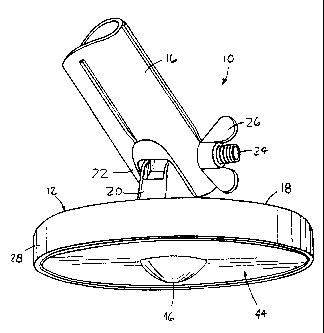
Un aimant à balayage permettant de recueillir des débris magnétiques présents sur une surface comprend une base et un aimant à deux faces, l'une étant couverte par la base et l'autre, apparente. Un couvercle recouvre cette seconde surface et comporte une saillie. Cette saillie crée automatiquement un espace minimal égale à au moins sa hauteur entre la surface et une partie au moins du couvercle afin d'attirer les débris magnétiques.


Abrégé anglais

A sweeper magnet for attracting magnetic debris from a pick-up surface includes a base assembly and a magnet having a first surface supported by the base assembly and a second surface. A cover extends over the magnet second surface and includes a projection having a projection height extending away from the magnet. The projection automatically creates a space distance of at least the projection height between the pick-up surface and at least a portion of the cover to provide clearance for attracting the magnetic debris

Revendications

Note : Les revendications sont présentées dans la langue officielle dans laquelle elles ont été soumises.


What is Claimed is:
1. A sweeper magnet for attracting magnetic debris from a pick-up surface,
the sweeper magnet comprising:
a base assembly;
a magnet having a first surface supported by the base assembly and a second
surface; and
a unitary cover extending over at least a portion of the magnet second
surface, the cover including a projection having a projection height extending
away from the magnet;
wherein the projection automatically creates a space distance of at least the
projection height between the pick-up surface and at least a portion of the
cover to
provide clearance for attracting the magnetic debris.
2. The sweeper magnet of claim 1, in which the projection extends from a
central portion of the cover and the cover includes a substantially planar
portion
surrounding the projection.
3. The sweeper magnet of claim 2, in which the cover includes a transition
area between the cover planar portion and the cover projection.
4. The sweeper magnet of claim 3, in which the transition area is formed with
a radius.
5. The sweeper magnet of claim 4, in which the transition area radius is equal
to approximately 0.1 inches.
6. The sweeper magnet of claim 1, in which the cover comprises a
ferromagnetic material, and in which the magnet secures the cover in place.
7. The sweeper magnet of claim 1, in which the base assembly includes a base
supporting the magnet and a coupling pivotably attached to the base.
-5-

8. The sweeper magnet of claim 7, in which the coupling includes a threaded
end.
9. The sweeper magnet of claim 1, further comprising a mounting cup having
a magnet recess sized to receive the magnet, wherein the magnet is secured to
the
mounting cup and the mounting cup is secured to the base assembly.
10. The sweeper magnet of claim 1, in which the projection comprises a
bubble.
11. The sweeper magnet of claim 1, in which the bubble is formed along a
radius of approximately 0.5 inches.
12. The sweeper magnet of claim 1, in which the projection height is equal to
approximately 0.25 inches.
13. A sweeper magnet for attracting magnetic debris from a pick-up surface,
the sweeper magnet comprising:
a base assembly including a base having a cylindrical side wall depending
from a top wall to define a cup recess, and a coupling pivotably attached to
the base;
a mounting cup sized for insertion into the base cup recess and attached to
the
base, the mounting cup defining a magnet recess;
an annular magnet sized for insertion into the mounting cup magnet recess, the
magnet including a first surface attached to the mounting cup and a second
surface;
and
a unitary cover sized to extend over at least a portion of the magnet
second surface, the cover including a projection having a projection height
extending away from the magnet;
wherein the projection automatically creates a space distance of at least the
projection height between the pick-up surface and at least a portion of the
cover to
provide clearance for attracting the magnetic debris.
-6-

14. The sweeper magnet of claim 13, in which the projection extends from a
central portion of the cover and the cover includes a substantially planar
portion
surrounding the projection.
15. The sweeper magnet of claim 14, in which the cover includes a transition
area between the cover planar portion and the cover projection.
16. The sweeper magnet of claim 15, in which the transition area is formed
with a radius.
17. The sweeper magnet of claim 16, in which the transition area radius is
equal to approximately 0.1 inches.
18. The sweeper magnet of claim 13, in which the cover comprises a
ferromagnetic material, and in which the magnet secures the cover in place.
19. The sweeper magnet of claim 13, in which the projection comprises a
bubble.
20. The sweeper magnet of claim 13, in which the projection height is equal
to approximately 0.25 inches.
-7-

Description

Note : Les descriptions sont présentées dans la langue officielle dans laquelle elles ont été soumises.


CA 02386280 2007-03-05
SWEEPER MAGNET
Field of the Invention
The present invention generally relates to pick-up tools and, more
particularly,
to sweeper magnets.
Background of the Invention
Conventional sweeper magnets typically include a magnet assembly attached
to an elongate handle. The magnet assembly includes a base adapted for
attachment
to the handle and a magnet attached to the base. During use, the magnetic
sweeper is
positioned in sufficient proximity to a pick-up surface so that the magnet
attracts
magnetic debris on the surface. The magnetic debris is pulled to the surface
of the
magnet or a magnet cover plate, and is subsequently removed, often manually.
Such conventional magnetic sweepers are overly difficult and cumbersome to
use. Care must be taken to insure that the magnet assembly is spaced a proper
distance from the pick-up surface. If the magnet assembly is spaced too far,
the
magnetic debris will not be attracted to the magnet. On the other hand, if the
magnet
assembly is spaced too close to the pick-up surface, there will be
insufficient
clearance to place the magnet assembly over the magnetic debris. Accordingly,
in
order to achieve the proper spacing, a user must manually support the magnetic
sweeper at a proper distance above the pick-up surface.
Some magnetic sweepers are known which include wheels for supporting the
magnet above the pick-up surface. These sweepers are typically large, as far
as
magnet pick-up tools are concerned, and the wheels are usually placed on
outside
ends of the magnet assembly. Accordingly, such magnetic sweepers are
unsuitable
for retrieving magnetic debris from pick-up surfaces having minimal clearance.
-1-

CA 02386280 2007-03-05
Summary of the Invention
The invention in one broad aspect provides a sweeper magnet for
attracting magnetic debris from a pick-up surface. The sweeper magnet
comprises a base assembly; a magnet having a first surface supported by the
base assembly and a second surface; and a unitary cover extending over at
least
a portion of the magnet second surface, the cover including a projection
having
a projection height extending away from the magnet. The projection
automatically creates a space distance of at least the projection height
between
the pick-up surface and at least a portion of the cover to provide clearance
for
attracting the magnetic debris.
Another aspect of the invention comprehends a sweeper magnet for
attracting magnetic debris from a pick-up surface, the sweeper magnet
comprising: a base assembly including a base having a cylindrical side wall
depending from a top wall to define a cup recess, and a coupling pivotably
attached to the base; a mounting cup sized for insertion into the base cup
recess
and attached to the base, the mounting cup defining a magnet recess; and an
annular magnet sized for insertion into the mounting cup magnet recess, the
magnet including a first surface attached to the mounting cup and a second
surface. A unity cover is sized to extend over at least a portion of the
magnet
second surface, the cover including a projection having a projection height
extending away from the magnet; wherein the projection automatically creates a
space distance of at least the projection height between the pick-up surface
and
at least a portion of the cover to provide clearance for attracting the
magnetic
debris.
Brief Description of the Drawings FIG. 1 is a top perspective view of a
sweeper magnet constructed in
accordance with the teachings of the present invention.
-1A-

CA 02386280 2002-05-15
FIG. 2 is a bottom perspective view of the sweeper magnet of FIG. 1.
FIG. 3 is an exploded perspective view of the sweeper magnet of FIGS. I and
2.
FIG. 4 is a side elevation view of a cover provided with the magnet sweeper of
FIGS. 1-3.
FIG. 5 is an enlarged detail of a portion of the cover of FIG. 4.
Detailed Description
An exemplary sweeper magnet 10 constructed in accordance with the
teachings of the present invention is illustrated in FIGS. 1-5. The sweeper
magnet 10
may be used to collect magnet debris from a pick-up surface. As used herein,
"magnetic debris" refers to any object formed of ferromagnetic material that
may be
retrieved by a sweeper magnet, such as screws, paperclips, and the like.
Furthermore,
"pick-up surface" refers to any surface on which magnetic debris may be
deposited.
The sweeper magnet includes a base assembly 12 attached to a coupling 16
adapted for removable attachment to an elongate handle (not shown). The
coupling
16 may include internal threads (not shown) that mate with external threads
provided
on the handle. The internal threads may be of a standard size so that the
coupling 16
may be removably attached to standard handles of various lengths.
The base assembly 12 includes a base 18 pivotably attached to the coupling 16
(FIG. 1). For example, the base 18 may include a boss 20 sized for insertion
into a
yoke 22 formed at an end of the coupling 16. A bolt 24 may then be inserted
through
holes formed in the boss 20 and yoke 22 and secured by a fastener 26.
Accordingly,
the coupling 16 may rotate with respect to the base 18 about the bolt 24, and
the
coupling 16 may be secured in selected angular positions with respect to the
base 18
by tightening the fastener 24.
As best shown in FIGS. 1 and 3, the base 18 includes a cylindrical side wall
28 depending from a peripliery of a top wa1130 to define a cup recess 32. A
mounting
cup 34 is sized for insertion into the cup recess 32 and, in turn, defines a
magnet
- recess 36. A magnet, such as annular magnet 38, has an outside diameter 40
sized for
insertion into the magnet recess 36. The magnet 38 has a first surface 39
adapted for
-2-

CA 02386280 2002-05-15
attachment, such as with an adhesive, to the mounting cup 34, and an exposed
second
surface 41. The magnet 38 and attached mounting cup 34 form a cup magnet
assembly 42 that may be inserted into the cup recess 32 and attached to the
base 18,
also preferably with an adhesive.
The base 18 and coupling 16 are preferably formed of a plastic (e.g., ABS or
nylon) or similar material that is easily molded into an attractive design,
while the
mounting cup 34 is made of a metal material.
A magnet cover 44 is positioned over a bottom face 46 of the magnet 38. The
cover 44 is generally circular and has an outside diameter 46 sized to closely
mach an
outside diameter of the mounting cup 34. The cover 44 may be secured in any
known
manner. In the exemplar embodiment, the cover 44 is formed of a ferromagnetic
material, so that the magnetic field generated by the magnet 38 holds the
cover 44 in
place.
The cover 44 includes a projection, such as bubble 46, for automatically
spacing the magnet 38 from a pick-up surface. In the illustrated embodiment,
the
bubble 46 is formed in a central portion of the cover 44, so that the cover 44
has a
generally planar annular portion 48 extending about a periphery of the bubble
46. As
best shown in FIG. 4, the bubble 46 has a height H so that, when the sweeper
magnet
10 is placed on a pick-up surface, at least a portion of the cover 44 is
spaced from the
pick-up surface by a distance equal to at least the height H. The height H is
selected
so that it creates sufficient clearance between the planar cover portion 48
and the
pick-up surface for common types of magnetic debris. In an exemplary
embodiment,
the height H is approximately 0.25 inches.
A transition area 50 of the cover 44, between the planar portion 44 and the
bubble 46, may be formed with a gradual slope so that the bubble 46 does not
snag or
catch on the pick-up surface. As best shown in FIG. 5, the transition area 50
is
formed with a radius r, which may be approximately 0.1 inches. Furthermore,
the
bubble 46 is formed with a continuous curve to avoid the formation of sharp
edges or
other profiles that may snag or damage the pick-up surface. As best shown in
FIG. 4,
the bubble 46 has a dome-'like shape with a constant radius R, which may be on
the
order of approximately 0.5 inches.
-3-

CA 02386280 2002-05-15
Although certain apparatus constructed in accordance with the teachings of the
invention have been described herein, the scope of coverage of this patent is
not
limited thereto. On the contrary, this patent covers all embodiments of the
teachings
of the invention fairly falling within the scope of the appended claims either
literally
or under the doctrine of equivalents.
-4-

Dessin représentatif
Une figure unique qui représente un dessin illustrant l'invention.
États administratifs

2024-08-01 : Dans le cadre de la transition vers les Brevets de nouvelle génération (BNG), la base de données sur les brevets canadiens (BDBC) contient désormais un Historique d'événement plus détaillé, qui reproduit le Journal des événements de notre nouvelle solution interne.

Veuillez noter que les événements débutant par « Inactive : » se réfèrent à des événements qui ne sont plus utilisés dans notre nouvelle solution interne.

Pour une meilleure compréhension de l'état de la demande ou brevet qui figure sur cette page, la rubrique Mise en garde , et les descriptions de Brevet , Historique d'événement , Taxes périodiques et Historique des paiements devraient être consultées.

Historique d'événement

Description Date
Le délai pour l'annulation est expiré 2022-03-01
Lettre envoyée 2021-05-17
Lettre envoyée 2021-03-01
Lettre envoyée 2020-08-31
Inactive : COVID 19 - Délai prolongé 2020-08-19
Inactive : COVID 19 - Délai prolongé 2020-08-06
Inactive : COVID 19 - Délai prolongé 2020-07-16
Inactive : COVID 19 - Délai prolongé 2020-07-02
Inactive : COVID 19 - Délai prolongé 2020-06-10
Inactive : COVID 19 - Délai prolongé 2020-05-28
Inactive : COVID 19 - Délai prolongé 2020-05-14
Inactive : COVID 19 - Délai prolongé 2020-04-28
Représentant commun nommé 2019-10-30
Accordé par délivrance 2009-08-11
Inactive : Page couverture publiée 2009-08-10
Inactive : Taxe finale reçue 2009-05-13
Préoctroi 2009-05-13
Lettre envoyée 2009-01-28
Un avis d'acceptation est envoyé 2009-01-28
month 2009-01-28
Inactive : Approuvée aux fins d'acceptation (AFA) 2008-12-30
Lettre envoyée 2007-03-13
Modification reçue - modification volontaire 2007-03-05
Exigences pour une requête d'examen - jugée conforme 2007-02-07
Toutes les exigences pour l'examen - jugée conforme 2007-02-07
Requête d'examen reçue 2007-02-07
Demande publiée (accessible au public) 2003-11-08
Inactive : Page couverture publiée 2003-11-07
Lettre envoyée 2002-09-05
Inactive : CIB attribuée 2002-08-14
Inactive : CIB en 1re position 2002-08-14
Inactive : Transfert individuel 2002-08-06
Demande de priorité reçue 2002-08-06
Inactive : Lettre de courtoisie - Preuve 2002-07-02
Inactive : Certificat de dépôt - Sans RE (Anglais) 2002-06-25
Demande reçue - nationale ordinaire 2002-06-25

Historique d'abandonnement

Il n'y a pas d'historique d'abandonnement

Taxes périodiques

Le dernier paiement a été reçu le 2009-05-15

Avis : Si le paiement en totalité n'a pas été reçu au plus tard à la date indiquée, une taxe supplémentaire peut être imposée, soit une des taxes suivantes :

  • taxe de rétablissement ;
  • taxe pour paiement en souffrance ; ou
  • taxe additionnelle pour le renversement d'une péremption réputée.

Les taxes sur les brevets sont ajustées au 1er janvier de chaque année. Les montants ci-dessus sont les montants actuels s'ils sont reçus au plus tard le 31 décembre de l'année en cours.
Veuillez vous référer à la page web des taxes sur les brevets de l'OPIC pour voir tous les montants actuels des taxes.

Titulaires au dossier

Les titulaires actuels et antérieures au dossier sont affichés en ordre alphabétique.

Titulaires actuels au dossier
NATIONAL MANUFACTURING COMPANY
Titulaires antérieures au dossier
COREY J. OTTENS
Les propriétaires antérieurs qui ne figurent pas dans la liste des « Propriétaires au dossier » apparaîtront dans d'autres documents au dossier.
Documents

Pour visionner les fichiers sélectionnés, entrer le code reCAPTCHA :


Pour visualiser une image, cliquer sur un lien dans la colonne description du document (Temporairement non-disponible). Pour télécharger l'image (les images), cliquer l'une ou plusieurs cases à cocher dans la première colonne et ensuite cliquer sur le bouton "Télécharger sélection en format PDF (archive Zip)" ou le bouton "Télécharger sélection (en un fichier PDF fusionné)".

Liste des documents de brevet publiés et non publiés sur la BDBC .

Si vous avez des difficultés à accéder au contenu, veuillez communiquer avec le Centre de services à la clientèle au 1-866-997-1936, ou envoyer un courriel au Centre de service à la clientèle de l'OPIC.


Description du
Document 
Date
(yyyy-mm-dd) 
Nombre de pages   Taille de l'image (Ko) 
Dessin représentatif 2002-11-11 1 11
Page couverture 2003-10-13 1 37
Abrégé 2002-05-14 1 15
Description 2002-05-14 4 162
Revendications 2002-05-14 3 95
Dessins 2002-05-14 3 64
Description 2007-03-04 5 197
Abrégé 2007-03-04 1 13
Revendications 2007-03-04 3 90
Dessin représentatif 2009-07-14 1 12
Page couverture 2009-07-14 1 38
Certificat de dépôt (anglais) 2002-06-24 1 173
Courtoisie - Certificat d'enregistrement (document(s) connexe(s)) 2002-09-04 1 112
Rappel de taxe de maintien due 2004-01-18 1 107
Rappel - requête d'examen 2007-01-15 1 124
Accusé de réception de la requête d'examen 2007-03-12 1 176
Avis du commissaire - Demande jugée acceptable 2009-01-27 1 163
Avis du commissaire - Non-paiement de la taxe pour le maintien en état des droits conférés par un brevet 2020-10-18 1 548
Courtoisie - Brevet réputé périmé 2021-03-28 1 540
Avis du commissaire - Non-paiement de la taxe pour le maintien en état des droits conférés par un brevet 2021-06-27 1 553
Correspondance 2002-06-24 1 30
Correspondance 2002-08-05 2 54
Correspondance 2002-09-05 1 10
Correspondance 2009-05-12 1 33