Note: Descriptions are shown in the official language in which they were submitted.
CA 02386443 2007-01-03
1 "REPLACEABLE FUEL MODULE AND METHOD"
2
3 FIELD OF THE INVENTION
4 The present invention relates to the field of vehicular fuel storage
and supply systems and more particularly to replaceable fuel systems for
6 alternative fuels such as compressed natural gas (CNG), hydrogen, and
liquefied
7 natural gas (LNG).
8
9 BACKGROUND OF THE INVENTION
Typically, on-board vehicular fuel supply systems comprise one or
11 more fuel tanks integrated into the chassis of a vehicle. Installation of
the fuel
12 system is a part of the vehicle's basic construction and is typically
performed in
13 assembly-line fashion at the factory.
14 Fuel systems such as described in US patent 5,794,979 to Kasuga
et al. are designed for alternative fuels such as CNG or LNG where a plurality
of
16 compressed pressurized fuel cylinders are mounted in a vehicle. A tank
17 supporting frame, installed complete with the fuel tanks and associated
pipes
18 and seals, is preferably installed through a rear window opening, during
initial
19 manufacture of the vehicle. The frame, following insertion into the fuel
storage
envelope in the vehicle, is subsequently bolted to the car body and the ends
of
21 the pipes connected to the ends of the fuel lines on the car body. Once
installed
22 in this fashion, the fuel system becomes an integral part of the vehicle
body and
23 cannot be readily removed for inspection, repair or replacement.
24 Malfunction in any part of the system results in costly repair and
significant down-time as the vehicle must be removed from the road. Costs
CA 02386443 2002-05-15
1 escalate with increasing time to disassemble portions of the vehicle to gain
2 access to the system, perforrn repairs and reassemble the vehicle.
3 US Patent 5,997,040 to Fukagawa et al. teaches a modularized
4 and compact fuel system comprising a support frame bolted to the car-body
side
supporting frame, a single fuel cylinder secured to the support frame using
belly
6 straps and a joint box for connection of the fuel and fill lines from the
tank to the
7 lines of the vehicle. The frame taught in Fukagawa is not readily adapted to
8 secure more than one fuel cylinder nor is there any indication that fuel
lines from
9 a plurality of fuel cylinders could be integrated into the joint box
provided.
Fukagawa teaches additional side frame components being bolted first at each
11 side of the car body prior to installation of the module. The fuel tank
attached to
12 the remaining portion of the frame is then inserted into the car body
through a
13 rear door and moved rearward between the wheel housings to align with the
side
14 frame component. Once aligned, the module is bolted into place. If
maintenance
is required, the reverse steps are performed including un-bolting all the
fasteners
16 for lifting the module free of the vehicle. Fukagawa avoids multiple
vessels so as
17 to ensure a compact module for ease of installation. A larger vessel or a
plurality
18 of vessels are not contemplated.
19 Where a plurality of vessels is required to increase the capacity of
the system, the single vessel system of Fukagawa is no longer applicable.
21 Clearly there is a need for a lightweight fuel system comprising a
22 plurality of pressurized fuel cylinders held together in a unitary
structure
23 complete with piping and valves that can be safely secured to the body of a
24 vehicle when in use, but be readily removable for service. Securing means
that
can be readily released, combined with removable piping connections would
2
CA 02386443 2002-05-15
1 allow the entire fuel system to be removed from its permitted dimensional
fuel
2 storage envelope in the vehicle for inspection or servicing. Further, a
modular
3 system could be replaced even on site, as a single module, should it
4 malfunction. Swapping of a replacement module for the faulty module permits
rapid repairs and also avoids unnecessary delays.
6
7
3
CA 02386443 2002-05-15
1 SUMMARY OF THE INVENTION
2 The present invention overcomes the prior art requirement for labor
3 intensive and costly servicing, inspection or replacement of a fuel system.
A
4 lightweight, unitary fuel system module is provided that can be quickly and
removably secured to a vehicle body. The module is easily unlatched from the
6 body and, with minimal detachment of piping connections, can be partially or
7 completely removed, as a complete module, from the vehicle for inspection,
8 repair or reinsertion. Should the module require unknown or extensive repair
or
9 component replacement, the entire used module can be replaced by a second
replacement module to minimize on-road time losses.
11 In a broad aspect of the invention, a modular fuel system is
12 provided for a vehicle having fuel lines and a fuel storage envelope, the
fuel
13 system comprising:
14 = one or more pressurized fuel cylinders;
= a frame iri which the one or more fuel cylinders are mounted
16 to form a replaceable module; and
17 = a latching mechanism attached to the frame and adapted for
18 cooperating with anchors in the envelope for releasably securing the
19 frame within the vehicular envelope and operable between a first secured
position and a second released position.
21 Such replaceable modules are self supporting during removal and
22 replacement steps. Preferably, each fuel cylinder has a longitudinal axis
and
23 opposing neck ends, the opposing neck ends of each of the one or more fuel
24 cylinders being neck-mounted to the frame. The fuel cylinders, associated
4
CA 02386443 2002-05-15
1 instrumentation and tubing are secured to the frame for insertion into the
vehicle
2 as a unitary module.
3 In a preferred embodiment of the invention, the fuel cylinders and
4 associated tubing are housed in a mounting frame comprising at least two end
brackets. The brackets are lightweight and designed to permit neck-mounting of
6 each fuel cylinder at opposing neck ends. The frame is secured to the
structure
7 of a fuel storage envelope within the vehicle using a releasable latching
8 mechanism capable of safely securing the frame under crash loading. Further,
9 the frame is fitted with means to allow easy removal of the system as a
module,
such as roller wheels or cooperating Teflon slides.
11 Preferably, the fuel cylinders are lightweight fiber reinforced,
12 aluminum-lined fuel cylinders having opposing neck-ends, capable of storing
13 pressurized fuel gas such as hydrogen. Instrumentation associated with
delivery
14 and monitoring of fuel is provided. Three lines of pressure tubing are
typically
used for connecting the fuel cylinders to the vehicle; a filling line, a fuel
line and a
16 venting line. Each line is housed within a mounting frame for connection to
the
17 fuel cylinders, in parallel. The fueling lines converge at a periphery of
the frame
18 for ease of connection to the vehicle. Removable fittings join the three
lines to
19 corresponding lines on the vehicle body. More preferably, the frame further
comprises crossbeams for additional structural rigidity and for attachment of
the
21 latching mechanism to the underside of the frame. With pressurized fuel
22 cylinders, the neck-mounting attachments are preferably adapted to permit
some
23 longitudinal expansion at least atone neck-mount.
5
CA 02386443 2002-05-15
1 In another aspect of the invention, a method for removal and
2 replacement of a used module of the present invention from a vehicle fuel
3 storage envelope is provided, the method comprising the steps of:
4 = providing at least two modules, a used module and a
replacement module, each module having one or more fuel cylinders
6 mounted to a frame, the frame having a latching mechanism for securing
7 the mounting frame to the vehicular envelope;
8 = disconnecting means for fluidly connecting the pressurized
9 fuel cylinders with fuel lines in the vehicle;
= actuating the latching mechanism of the used module from a
11 first secured position to a second released position; then sequentially
12 = removing the used module from the vehicle's envelope;
13 = inserting a replacement module into the vehicle's envelope;
14 and then
= actuating the latching mechanism of the replacement
16 module for securing the mounting frame to the vehicle from a second
17 released position to a first secured position; and
18 = reconnecting the means for fluidly connecting the
19 pressurized fuel cylinders with the fuel lines in the vehicle.
The method is particularly convenient when two or more fuel
21 cylinders are involved in the module.
22
6
CA 02386443 2002-05-15
1 BRIEF DESCRIPTION OF THE DRAWINGS
2 Figure 1 is a perspective view of the fuel system module of the
3 present invention;
4 Figure 2 is a perspective view of the fuel system module of Fig. 1
installed in a rear fuel storage envelope in a vehicle and having a cut away
in
6 one fuel cylinder to show an anchoring mechanism of the present invention
7 securing the module into the envelope;
8 Figure 3 is a perspective view of the fuel system module of Fig. 1
9 partially installed in an underbody fuel storage envelope in the side of a
vehicle;
Figure 4 is a perspective view of the frame of the fuel system
11 module of Figure 1 showing the brackets, cross-beams; anchoring mechanism
12 and neck-mounting attachments;
13 Figure 5 is a perspective view of the frame of the fuel system
14 module according to Figure 4 without the neck-mounting attachments;
Figure 6 is a perspective view of the underside of the fuel system
16 module according to Figure 1 showing the anchoring mechanism in a secured
17 position and the wheels retracted;
18 Figure 7 is a front view of the underside of the fuel system module
19 according to Figure 1 showing the anchoring mechanism; and
Figure 8 is a schematic illustrating the valving and tubing
21 connections of the pressurized fuel cylinders using an external pressure
22 regulator.
23
7
CA 02386443 2002-05-15
1 DETAILED DESCRIPTION OF THE PREFERRED EMBODIMENT
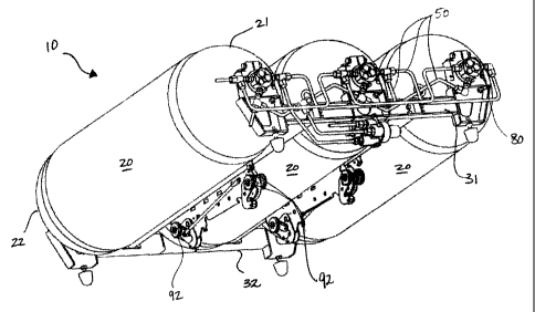
2 Having reference to Figs. 1 - 3, a modular fuel system 10 of the
3 present invention is shown. A plurality of pressurized fuel cylinders 20 are
4 attached to a frame 30 for insertion, as a module 10, into a fuel storage
envelope
40 in a vehicle 100. Further, fueling tubing or lines 50 associated with
filling and
6 venting the fuel cylinders 20, as well as fueling the vehicle 100, are
provided. As
7 shown in Figs. 2 and 3, the frame 30 is secured to the structure of the fuel
8 storage envelope 40, using a releasable latching mechanism 60.
9 The frame, as shown in Figs. 4-5, comprises first and second end
brackets 31, 32 spaced and secured to the fuel cylinders 20. Preferably, one
or
11 more cross beams 33 extend between the brackets 31,32 in part to provide
12 additional structural rigidity and to provide additional points of
attachment as
13 necessary. One or more sets of neck-mounting attachments 34a, 34b are
bolted
14 to the frame brackets 31,32 for neck-mounting opposing neck ends 21, 22 of
each pressurized fuel cylinder 20.
16 Alternatively, fuel cylinders 20 can be mounted to the crossbeams
17 33 of the frame 30, using conventional belly straps (not shown).
18 Preferably, the pressurized fuel cylinders 20 are fixed at threaded
19 neck-mounting attachments 34a at one or either end bracket 31,32 of the
frame
30 by a fixed or threaded neck end 21, 22 into which a valve assembly 55 and
21 fueling lines 50 are fit (Fig. 7). The neck-mounting attachments 34b at the
22 opposing ends of the fuel cylinders 22, 21 are slidably fit, such as with
plastic
23 bushings (not shown), which support the fuel cylinder's neck end 22 yet
still
24 allows for lineal expansion of the pressurized fuel cylinders 20 such as
under
fill/empty pressures cycles.
8
CA 02386443 2002-05-15
1 In one embodiment of the invention, as shown in Figs. 4-7, the
2 latching mechanism 60 comprises one or more anchoring mechanisms 60a fixed
3 to the frame 30, such as to the cross-beams 33. Each anchoring mechanism 60a
4 comprises a support bracket 61, having a first hook 62 at a first end 63 and
a
second hook 64 at a second end 65 of the support bracket 61. Each hook 62,64
6 is pivotally attached to the support bracket 61 and can be actuated from an
7 open, released position to a closed, secured position. The hooks 62,64
happen
8 to be oriented with open sides 66 facing in opposing directions (shown
facing
9 away from each other) for co-operating with corresponding and complementary
anchors 74 (as seen in Fig. 2) in the envelope 40.
11 Each hook 62,64 is pivotally connected to the support bracket 61
12 and to an actuation arm 67 at the arm's first 68 or second end 69
respectively.
13 For contra-rotation of the opposing hooks, the actuation arm 67 extends
from a
14 top 70 of the first hook 62 to a bottom 71 of the second hook 64. The
actuation
arm 67 is further connected to a handle 72 at the first end 63. As the handle
72
16 is depressed, the adjacent first hook 62 is caused to pivot about its
attachment
17 73 to the support bracket 61, the open side 66 pivoting downward, to a
released
18 position. At the same time, the second hook 64 is caused to pivot downward,
19 also to a released position. When the handle 72 is lifted, the hooks 62,64
are
caused to pivot away from one another to a secured position in engagement with
21 anchors 74 formed in the envelope 40 (Fig. 2.).
22 Optionally, the handle 72 is positioned at a periphery of the frame
23 30 or at a location remote from the module 10 to provide easy access for
24 actuating the latching mechanisms 60. This may be of particular importance
in
9
CA 02386443 2002-05-15
1 vehicular envelopes 40 that are severely space-restricted where access to
the
2 underside of the frame 30 is limited.
3 As shown in Fig. 2, loop-like anchors 74 are provided in the
4 structure of the fuel storage envelope 40, typically at a base 41 of the
envelope
40, through which the hooks 62,64 of the anchoring system 60a extend when in
6 the secured position. In this secured position, the frame 30 is safely
secured to
7 the vehicle 100. Finite element analysis of the module 10 confirms
structural
8 performance under regulatory requirements such loading with 25g in planes
9 parallel and perpendicular to the pressurized fuel cylinder's axis and 5g in
the
vertical plane. One form of the latching mechanisms of the type herein
disclosed
11 are typically found in the automobile industry for use in securing rear
bench
12 seats to the vehicular frame.
13 As shown in Figs. 7-8, typical fueling lines 50 comprise a fill line 51,
14 a fuel line 52 and a venting line 53 which are connected to corresponding
lines
(not shown) in the vehicle 100. The fueling lines 50 are carried on or secured
to
16 the frame 30 connecting two or more fuel cylinders 20 in parallel.
17 Instrumentation or electrical control lines (not shown), as required, are
also
18 carried within the frame 30. Further, the fueling lines 50 converge at a
periphery
19 of the frame 30, and the envelope 40, for ease of connection to the
2,0 corresponding lines in the vehicle 100. Connection is accomplished using
21 releasable fittings between the corresponding lines.
22 Turning to Fig. 8, the fill line 51 allows the fuel cylinder 20 to be
23 filled with compressed gas from an outside source. Check valves 54 are
24 installed in each fuel cylinder's valve assembly 55. A fuel filter 56 is
installed
between the filling receptacle (not shown) and the valve assembly 55 to
prevent
CA 02386443 2002-05-15
1 contamination entering the system. Fuel from the fuel cylinders 20 is
directed
2 through one ore more pressure regulators 81. A pressure switch 57 (P1), used
3 to shut off the system in case of over-pressure and a manual valve 58 used
for
4 defueling, are also connected to the fuel line 52. The venting line 53 is
required
for gas release from temperature and pressure-activated relief devices (PRD's)
6 80.
7 Further as part of a typical instrumentation package, the module 10
8 is provided with at least one temperature sensor T and one pressure sensor
P2
9 which indicates the pressure inside the fuel cylinder 20 when an electro-
magnetic or solenoid shut-off valve 59 is opened. As shown in Figs. 7 and 8, a
11 pressure regulator 81 can be connected externally to the fuel line 52.
12 Typical parameters for a module 10 as described include 250 or
13 350 bar (gauge) pressurized fuel cylinders 20 and pressure regulators
having
14 transducers in the range of nominal 0-450 bar (gauge).
Preferably, the frame 30 is spaced from the structure of the fuel
16 storage envelope 40 by anti-vibration pads 90 which are compressed when the
17 latching mechanism 60 is actuated.
18 More preferably, the frame 30 is further provided with means 91
19 such as wheels or co-operating Teflon slides which are supported by the
envelope 40, to assist in removing and inserting the module 10 into and out of
21 the fuel storage envelope 40.
22 In one embodiment of the invention, as shown in Figs. 4-7, at least
23 one wheel 92 is attached to the anchoring mechanism 60a and pivotally
actuated
24 with the hooks 61, 63. Actuation of the anchoring mechanism 60a to the
released position causes the hooks 61,63 to be released and the wheels 92 to
11
CA 02386443 2002-05-15
1 pivot to a downward position where they contact the structure of the fuel
storage
2 envelope 40 and raise the frame 30 slightly so as to assist in removing or
3 inserting the module 10 into the fuel storage envelope 40. Further, eyelets
101
4 are provided on each bracket 31, 32 to assist in lifting the module once it
has
been removed from the vehicle.
6 In use, a used module 10 is removed for inspection or, if required,
7 is rapidly replaced by a substantially identical replacement module 10. The
8 fittings, which connect the fueling lines 50 on the fuel cylinders 20 to the
fuel
9 lines in the vehicle 100, are typically disconnected first. Removal of the
used
module 10 is accomplished by actuating the anchoring mechanism 60a on the
11 frame 30 to a released position to release the frame 30 from its attachment
to
12 the anchors 74 in the structure of the fuel storage envelope 40. While it
is not
13 essential to release the frame or disconnect the fueling lines in any
particular
14 order, one does avoid disruption of the fuel lines 50 if they are
disconnected
before releasing the used module. The used module 10 can then be removed
16 from the fuel storage envelope 40 as a unitary structure and either
repaired or
17 replaced with a replacement module 10 in the reverse order.
18 Optionally, in embodiments wherein the handle 72 of the anchoring
19 mechanism 60a is appropriately situated, actuation of the anchoring
mechanism
60a, is performed at a location at the periphery of the frame 30 or otherwise
21 remote from the module 10, particularly in envelopes 40 that are severely
space-
22 restricted and where access to the anchoring mechanism is difficult.
23
12