Note: Descriptions are shown in the official language in which they were submitted.
CA 02386603 2002-04-02
WO 01/27239 PCT/USOO/27973
SEMI-ENCLOSED APPLICATOR FOR DISTRIBUTING A SUBSTANCE
ONTO A TARGET SURFACE
FIELD OF THE INVENTION
The present invention relates to a semi-enclosed applicator useful for
distributing
substances onto target surfaces. The present invention also relates to such an
applicator that also
contains a substance for application to the surface of a target object. More
particularly, the
present invention relates to such applicators wherein the substance may be
released from the
applicator material and distributed upon the surface of the target object,
then removed from the
surface and absorbed by the applicator.
BACKGROUND OF THE INVENTION
In the art of dispensing, articles have been developed which are coated or
impregnated
with useful substances intended to be utilized when the article is contacted
with a target surface.
While there are advantages with having the substance present on or near the
surface of such
articles, there is often the drawback that the useful substance is unprotected
and is subject to
inadvertent contact before intended use. Inadvertent contact may lead to
contamination of the
substance, loss of the substance onto surfaces other than the desired target
surface, and/or
contamination of such other surfaces with the substance. Moreover, the use of
such articles to
manually apply a substance to a surface of an object frequently results in
exposure of a user's
hands to the substance. At the very least such a scenario results in a waste
of product and is
undesirable from an aesthetic standpoint and, at worst, results in excessive
exposure of the user
1
CA 02386603 2002-04-02
WO 01/27239 PCT/USOO/27973
to potentially harmful, toxic, or otherwise undesirable substances.
Other common approaches involve dispensing a substance such as a cleaner or
protectant
from a bottle or other closed vessel onto the target surface, then utilizing a
sponge, towel, brush,
or other implement to distribute the product on the surface and, if desired,
absorb any excess
product, potentially with another implement or substrate. Such practices are
commonplace with
surfaces such as glass, countertops, and other kitchen and bathroom surfaces.
While such
practices are widely accepted, they often result in inefficient use of product
and/or contact with
the substances involved. Moreover, utilizing such an implement typically only
provides one type
of material surface for use in contacting the substance and the target
surface. Applying the
substance to the applicator from a vessel at the point of use likewise often
results in inefficient
use of product and/or contact with the substances involved.
A common approach to cleaning glass or other surfaces, for example, is to
spray cleaning
solution onto the surface and then wipe the surface with a paper towel.
Spraying the cleaning
solution usually wastes some of the cleaning solution due to over-spray
landing on areas not
intended to be cleaned. This over-spray is often undesirable since some
surfaces can be harmed
by this cleaning solution or at a minimum requires additional surfaces to be
cleaned. The paper
towel is used to both spread the cleaning solution on the surface as well as
absorbing any excess.
The paper towel has a difficult time spreading the cleaning solution since it
is typically designed
to be highly absorbent. To compensate, a disposable paper towel can be made
partially
saturated making it easier to spread the cleaner. This however typically makes
the towel weaker
due to a paper towel's lack of wet strength. Then a separate dry paper towel
can be used to buff
the glass dry and to absorb any excess cleaner. This approach requires more
cleaning solution to
be applied and requires more paper towels than desired. To compensate for this
approach some
consumers use newspaper quality paper or low absorbency paper towels. This
type of paper has
a lower absorbency level and naturally does a better job of spreading the
cleaning solution
instead of absorbing the cleaner into the paper towel. Also these types of
towels have a stiffer
and harder furnish which tend to aid in buffing the glass to a streak-free
shine. However, this
approach is less desired because special paper towels are required and a lot
of buffing is required
to get the desired end result.
Accordingly, it would be desirable to provide an applicator for applying a
substance to a
target surface that permits greater control by the user during the application
process.
2
CA 02386603 2002-04-02
WO 01/27239 PCT/USOO/27973
It would also be desirable to provide such an applicator that permits the user
to apply a
substance to a target surface with reduced messiness and waste of the
substance.
It would further be desirable to provide such an applicator that provides
multiple surfaces
of diverse materials and/or multiple substances for use in multiple tasks.
SUMMARY OF THE INVENTION
The present invention provides a semi-enclosed applicator for distributing a
substance
onto a target surface and a method for making such an applicator. The
applicator has a first side,
a second side, and an internal cavity between the first and second sides. The
applicator further
includes at least one opening, such that the internal cavity is externally
accessible, and, in a
preferred embodiment, the applicator further comprises: (a) a substantially
non-absorbent fibrous
material on one of the first and second sides; (b) a substantially absorbent
fibrous material on the
other of the first and second sides; and (c) substantially fluid-impervious
barrier layer within the
internal cavity adjacent the non-absorbent material.
The present invention also provides a semi-enclosed applicator for
distributing a
substance onto a target surface, the applicator having a first side, a second
side, and an internal
cavity between the first and second sides. The applicator further includes at
least one opening,
such that the internal cavity is externally accessible, and the applicator
further comprises: (a) a
substantially fluid-impervious barrier layer within the internal cavity
adjacent one of the sides;
and (b) a rupturable fluid-containing reservoir located between the barrier
layer and the side.
BRIEF DESCRIPTION OF THE DRAWINGS
While the specification concludes with claims which particularly point out and
distinctly
claim the present invention, it is believed that the present invention will be
better understood
from the following description of preferred embodiments, taken in conjunction
with the
accompanying drawings, in which like reference numerals identify identical
elements, reference
numerals with the same final two digits identify corresponding elements, and
wherein:
Figure 1 is a plan view of a preferred embodiment of a semi-enclosed
applicator in
accordance with the present invention, in the form of a mitt;
Figure 2 is a cross-sectional view of the mitt of Figure 1 taken along line 2-
2;
Figure 3 is another embodiment of a semi-enclosed applicator in accordance
with the
3
CA 02386603 2007-02-14
present invention, also in the form of a mitt;
Figure 4 is a plan view of one embodiment of a rupturable reservoir suitable
for use in
accordance with the present invention;
Figure 5 is a plan view of another embodiment of a rupturable reservoir
suitable for use
in accordance with the present invention;
Figure 6 is a plan view of a further embodiment of a rupturable reservoir
suitable for use
in accordance with the present invention;
Figure 7 is a plan view of a further embodiment of a rupturable reservoir
suitable for use
in accordance with the present invention;
Figure 8 is an elevational view of the rupturable reservoir of Figure 7;
Figure 9 is an elevational view of the rupturable reservoir of Figure 8 folded
in the
vicinity of the rupturable seal;
Figure 10 is an elevational view of an applicator similar to that of Figure 3
which is
folded in the vicinity of the rupturable seal of the rupturable reservoir;
Figure 1 l is a cross-sectional view of an applicator similar to that of
Figures 1 and 2, but
illustrating the use of rugosities on at least one surface;
Figure 12 is a partial perspective view of one material useful in forming the
rugosities of
Figure 11;
Figure 13 is a perspective view of an exemplary finger mitt applicator made in
accordance with the present invention;
Figure 14 is a cross-sectional view of the finger mitt applicator of Figure
13, taken along
line 14-14;
Figure 15 is a schematic illustration of an applicator manufacturing process
in
accordance with the present invention;
Figure 16 is a plan view of the process of Figure 15;
Figure 17 is a plan view of a further embodiment of a semi-enclosed applicator
in
accordance with the present invention, also in the form of a mitt;
Figure 18 is a plan view of a further embodiment of a semi-enclosed applicator
in
accordance with the present invention, also in the form of a mitt;
Figure 19 is a plan view of a further embodiment of a rupturable reservoir
suitable for
use in accordance with the present invention;
4
CA 02386603 2002-04-02
WO 01/27239 PCT/USOO/27973
Figure 20 is a plan view of a further embodiment of a rupturable reservoir
suitable for
use in accordance with the present invention;
Figure 21 is a plan view of a further embodiment of a rupturable reservoir
suitable for
use in accordance with the present invention;
Figure 22 is a plan view of a further embodiment of a semi-enclosed applicator
in
accordance with the present invention, in the form of a mitt;
Figure 23 is a cross-sectional view of the mitt of Figure 22 taken along
section line 23 -
23;
Figure 24 is a plan view of a further embodiment of a rupturable reservoir
suitable for
use in accordance with the present invention;
Figure 25 is a plan view of a mitt with seal line elements to aid keeping mitt
from
shifting on hand during use;
Figure 26 is a top view of a temperature changing element of one embodiment of
the
present invention;
Figure 27 is a side view of a temperature changing element of one embodiment
of the
present invention;
Figure 28 is a top view of a temperature changing element of one embodiment of
the
present invention;
Figure 29 is a side view of a temperature changing element of one embodiment
of the
present invention;
Figure 30 is a top view of a temperature changing element of one embodiment of
the
present invention;
Figure 31 is a side view of a temperature changing element of one embodiment
of the
present invention;
Figure 32 is a top view of a temperature changing element of one embodiment of
the
present invention;
Figure 33 is a side view of a temperature changing element of one embodiment
of the
present invention;
Figure 34 is a top view of a temperature changing element of one embodiment of
the
present invention.
Figure 35 is a side view of a temperature changing element of one embodiment
of the
5
CA 02386603 2002-04-02
WO 01/27239 PCT/US00/27973
present invention;
Figure 36 is a top view of a temperature changing element of one embodiment of
the
present invention;
Figure 37 is a side view of a temperature changing element of one embodiment
of the
present invention;
Figure 38 is a top view of a temperature changing element of one embodiment of
the
present invention;
Figure 39 is a side view of a temperature changing element of one embodiment
of the
present invention;
Figure 40 is a top view of a temperature changing element of one embodiment of
the
present invention;.
Figure 41 is a side view of a temperature changing element of one embodiment
of the
present invention;
Figure 42 is a top view of a temperature changing element of one embodiment of
the
present invention;
Figure 43 is a side view of a temperature changing element of one embodiment
of the
present invention;
Figure 44 is a top view of a temperature changing element of one embodiment of
the
present invention;
Figure 45 is a side view of a temperature changing element of one embodiment
of the
present invention;
Figure 46 is a plan view of one embodiment of a rupturable two component
heating or
cooling reservoir suitable for use in accordance with the present invention;
Figure 47 is an elevational view of the rupturable heating or cooling
reservoir of Figure
46;
Figure 48 is a plan view of one embodiment of a rupturable two component
heating or
cooling reservoir with an integral product dispensing reservoir suitable for
use in accordance
with the present invention;
Figure 49 is an elevational view of the rupturable heating, cooling, and
dispensing
reservoir of Figure 48;
Figure 50 is an elevational view of the rupturable heating, cooling, and
dispensing
6
CA 02386603 2007-02-14
reservoir of Figure 48 folded as when assembled into a mitt;
Figure 51 is an elevational view of the rupturable heating or cooling
reservoir of Figure
46 adjacent to the rupturable reservoir of Figure 4;
Figure 52 is a cross-sectional view of a mitt described for use dusting and
polishing
furniture;
Figure 53 is a cross-sectional view of the mitt in figure 54 taken along line
53-53 of Figure 57;
Figure 54 is a top plan view of mitt described for body cleansing;
Figure 55 is a cross-sectional view of a lotion applicator;
Figure 56 is a top plan view of an embossing pattern for texturing films,
nonwovens,
papers and other materials;
Figure 57 is a top plan view of one embodiment of a glove of the present
invention;
Figure 58 is a plan view of a preferred embodiment of a semi-enclosed
heating/cooling
applicator in accordance with the present invention, in the form of a mitt;
Figure 59 is a cross-sectional view of the mitt of Figure 58 taken along line
59-59;
Figure 59 is a cross-sectional view of the mitt of Figure 58 taken along line
59-59;
Figure 60 is a top plan view of a mitt with an optional scrubbing strip
attached to front
panel;
Figure 61 is a cross-sectional of a bathroom cleaning mitt with barrier layers
on both
sides of band; and
Figure 62 is a cross-sectional of a flushable wet and dry mitt.
DETAILED DESCRIPTION OF THE INVENTION
As used herein, the term "hand article" refers to a covering for the hand or
portion of the
hand such as a finger or thumb. The term "disposable" is used herein to
describe hand articles
that are not intended to be restored or reused (i.e., they are intended to be
discarded after a single
use or a limited number of uses, and preferably, to be recycled, composted or
otherwise disposed
of in an environmentally compatible manner). As used herein the term "glove"
refers to a
covering for the hand having separate sections for each finger. As used
herein, the term "mitt"
refers to a covering for the hand having an enclosure that leaves some or all
of the fingers
partially or wholly unseparated and that may include space for the thumb in
the main enclosure
or may provide space for the thumb in a separate enclosure for the thumb or
may not include a
7
CA 02386603 2002-04-02
WO 01/27239 PCT/USOO/27973
thumb enclosure at all. This term is also applicable to an apparatus which
covers only one or
more digits of a user, such as in the case of a "finger mitt" as described
below. While the terms
"glove" and "mitt" have been defined with respect to the human hand, similar
structures could be
utilized to cover or enclose other elements of human anatomy, such as foot
coverings, or other
items for which coverings of a particular shape are preferred. As used herein,
the term "absorb"
refers to the penetration of one substance into the mass of another. ASTM
standard test method
D2654-89a "Standard Test Methods for Moisture in Textiles" should be used to
determine the
percentage of a liquid, such as water, absorbed and retained. An absorbent
fiber for the purposes
of the present invention has a moisture regain according to the ASTM standard
test method
D2654-89a of greater than about 5% (e.g., a cellulose acetate fiber having a
moisture regain of
about 6.5%). A non-absorbent fiber for the purposes of the present invention,
however, has a
moisture regain of less than about 5% (e.g., a polyester fiber having a
moisture regain of about
4%). As used herein the term "substantially non-absorbent" is defined as a
material composed of
a majority of non-absorbent fibers or webs. As used herein the term
"substantially absorbent" is
defined as a material composed of a majority of absorbent fibers or webs. As
used herein the
term "extension force" refers to forces applied by hand movements to a surface
to extend and/or
bend that surface linearly and/or curvilinearly. The term "pouch" or "sachet"
is intended to refer
to a reservoir made from flexible film that is bonded to create one or more
enclosed
compartments for containing a substance.
The term "semi-enclosed applicator" is intended to refer to an applicator
device having at
least one externally-accessible internal cavity for receiving a portion of
human anatomy such as a
hand or finger so that the applicator device may be used as an implement. A
glove, mitt or finger
mitt would be an example of such a semi-enclosed applicator in the context of
the present
invention.
Applicator Construction and Operation:
A representative embodiment of a semi-enclosed applicator of the present
invention in
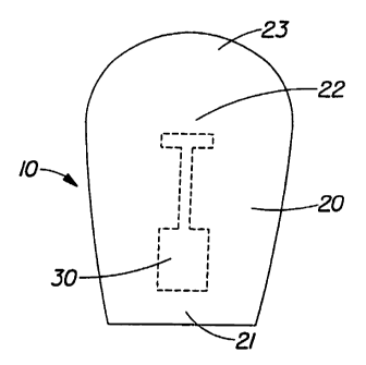
the form of a hand article is the disposable mitt 10 shown in Figure 1. Figure
1 is a plan view of
the mitt 10 of the present invention in its flat-out state illustrating the
body portion 20, cuff
portion 21, central portion 22, distal portion 23, and reservoir 30. In
general terms, the mitt 10
has an internal cavity that is accessible through an opening in the cuff
portion and that extends
8
CA 02386603 2002-04-02
WO 01/27239 PCT/USOO/27973
inwardly toward the distal end that is closed.
Figure 2 shows the construction details of the mitt 10 more specifically. The
mitt 10 has
a front outer surface 31, a front inner surface 32, a back outer surface 33,
and a back inner
surface 34. The front and back inner surfaces define a hollow interior 29 into
which a hand may
be inserted through an opening in the cuff portion 21. The mitt 10 includes a
front panel 24,
which defines the front outer surface 31, and a back panel 26, which defines
the back outer
surface 33. The front and back panels are connected along their periphery to
form a seam 36.
The seam 36 can be straight or may be tapered. For example, the seam 36 in may
be inwardly
tapered in the area of the cuff region to allow the applicator to stay on the
hand of the user better.
In addition to, or in place of, tapered seams, elastic material may be added
in the cuff region to
keep the applicator on the hand of the user.
A semi-enclosed applicator of the present invention may be constructed for
many
different uses. Unlike conventional cleaning implements, the applicators are
ideally suited for
cleaning curved or other surfaces with jagged edges or tough to reach areas.
As a result, the
product form provides convenience not only because it may comprise multiple
different surfaces
that may perform complementary tasks such as wetting, cleaning, drying and/or
buffing surfaces,
but also because it provides a means of doing the job on tough to reach areas
or surfaces. Such a
combination of benefits is lacking in present day cleaning systems. The mitts
can be stored
individually, or placed and stacked in containers, folded or unfolded. As
such, they occupy little
space and can be stored in small areas, which improves convenience for the
users. The
combination of easy storage and ability to clean tough to reach areas such as
the interior of car
windows, dashboards steering wheels and mirrors, makes them ideal for use in
the car (glove
compartment storage), where conventionally employed glass cleaning processes
are awkward,
ineffective and potentially hazardous.
Reservoir
The reservoir 30 contains a product that may be dispensed and/or dispersed
from the
reservoir 30 to one or more of the outer surfaces of an applicator, such as
outer surface 31, for
delivery to a target surface. The fluid reservoir 30 may be of any suitable
size, configuration, and
composition for the intended product to be dispensed and dispersed. The
product may be a
liquid, a gel, a lotion, a cream, a powder or even a solid. A solid such as a
wax, for example,
9
CA 02386603 2002-04-02
WO 01/27239 PCT/US00/27973
may be heated to provide a flowable product that may be dispensed and/or
dispersed from the
reservoir 30. One aspect of the reservoir 30, which is believed to be
important to the overall
functionality of the mitt 10, is the ability of a sealed, fully-enclosed
reservoir to rupture or
otherwise dispense the product contained therein when "activated" by the user
and yet resist
premature dispensing during manufacture, packaging, and shipment. In alternate
embodiments,
the reservoir may be located at least partially outside of the applicator 10.
For example, chamber
47 of reservoir 30 of Figure 7 might extend outwardly from an applicator for
improved visual and
manual access, as desired. The ability of the reservoir to survive intact
until the point of use
preserves the quality and quantity of the liquid until the time of use. As
will be understood,
external accessibility to a reservoir might also facilitate the provision of
crimping devices,
folding of a reservoir or other protection of the reservoir against premature
dispensing, as will be
discussed further below. Alternatively, the reservoir 30 may be a separate
article that can be
inserted into the mitt 10 by the user. For example, the reservoir 30 may be
inserted inside of the
front panel 24 or the back panel 26 of the mitt 10 or may be inserted into one
or more pockets
located between the front outer surface 31 and the front inner surface 32 that
are designed to
receive the reservoir 30. This allows the user to replace reservoirs 30 as
needed and provides for
reuse of the mitt 10 if it retains sufficient absorbency, wet strength, etc.
In one embodiment, the rupturable reservoir can be designed to burst or
rupture to release
the product contained within the reservoir at a comparatively low force when
desired by the
consumer. This may be accomplished by having a sealed pouch with permanent
seals and also
seals that are "frangible", i.e., rupturable. When the pouch is squeezed, the
frangible seal will
yield or fail first since it has a lower peel force to break the seal apart
than the permanent seals.
In one embodiment, the frangible seal will ideally rupture with 1-3 lbs of
force when applied by
the consumer. Adding stress concentrators in the seal geometry that will
localize forces at a
particular location can optimize the location of rupture. These stress
concentrators can be shaped
like a V, a notch, a half circle or a variety of other shapes depending upon
the desired burst level.
These stress concentrators will help control the force required to burst the
pouch as well as the
location of where the seal will rupture. Such stress concentrators thereby
focus or concentrate
external pressure or mechanical forces imposed on the reservoir and its
contents. For example,
pressurizing a pouch having a V-notch seal such as shown in Figure 7 will
localize forces first at
the apex of the V, causing that region to rupture first. Such an arrangement
can help reduce
CA 02386603 2002-04-02
WO 01/27239 PCT/USOO/27973
potential variability in rupture or dispensing forces and the location where
the rupture occurs.
Additionally, other seal angles and geometries of the seal can also be used to
tailor dispensing
forces for particular applications.
In the embodiment of Figure 1, the reservoir 30 is positioned in the central
portion 22 of
the mitt 10. In this location, the reservoir 30 can be subjected to sufficient
force to rupture the
reservoir and dispense the liquid by making a fist with the user's hand, by
applying force with the
opposite hand, or by pressing the palm against the target surface. This
location of the reservoir
30 in the applicator is convenient for applications where it is desired for
the product to be
dispensed all at once or while rubbing a surface. It may also be desired to
have the reservoir
located in a portion of the applicator that is spaced or remote from a
location where forces are
applied during cleaning or rubbing. In this manner, pressure applied to the
mitt during cleaning
or rubbing will not cause premature dispensing or dosing of the product in the
reservoir 30.
Figure 3, for example, depicts an alternative embodiment of a mitt 10 wherein
the reservoir 30 is
positioned closer to the cuff region 21. In this location, the reservoir 30 is
not located in a region
of the mitt that would typically encounter forces in use (the application or
pressure region), and
the reservoir 30 would require activation by specifically applying force to
the cuff region. Such
an embodiment may be particularly advantageous where progressive dispensing of
discrete
quantities of the product is desired rather than an "all at once" dispensing
upon application of an
initial force.
The use of a reservoir to contain a product allows the applicator to become
wet on the
desired side only when wanted by the person using the applicator. In some
cases a person would
like to store a single applicator in a remote site such as a glove box in a
car or in a separate
drawer in a bathroom. The hermetically sealed reservoir(s) in the applicator
preferably use
sufficient barrier materials to allow these individual applicators to have
multi-year shelf life even
when stored as individual units. Separately, the reservoirs can be placed on
one or both sides of
the applicator or in multiples on the same side. This allows one side to be
kept dry or to have
different products on the different sides. In contrast, pre-moistened wet
wipes that have been
individually wrapped are traditionally placed in a foil pouch. This foil pouch
material is
expensive and more of it is needed to enclose the entire wipe to prevent
moisture loss (with the
individually enclosed reservoir, foil film is only needed to enclose the
liquid or substance). This
approach of putting the entire pre-moistened applicator (wipe) in a foil pouch
also makes it
11
CA 02386603 2002-04-02
WO 01/27239 PCT/USOO/27973
difficult for the wipe to have a dry surface or from having surfaces with two
different substances
since cross-contamination is likely to occur.
Figure 4 illustrates one suitable configuration for a rupturable reservoir 30
suitable for
use with applicators according to the present invention, such as the
applicator of Figure 1. In the
embodiment of Figure 4, the reservoir 30 includes a chamber 38, a frangible
seal 40, and at least
one dispensing aperture 39. The embodiment of Figure 4 may be made by
peripherally joining
two similarly-sized and shaped pieces of fluid-impervious material with
substantially permanent
seals, forming the dispensing apertures in one portion of at least one of the
pieces of material,
introducing the product through one of the apertures, and then forming a
frangible seal of limited
strength to separate the chamber 38 from the apertures 39. Other forming
techniques, such as
folding a single piece of material double upon itself and sealing, or rolling
and sealing a piece of
material to form a sleeve, may also be utilized.
Figure 5 depicts another embodiment of a reservoir 30 that is functionally
similar to that
of Figure 4, but including a plurality of chambers 38 for containing liquid.
Respective chambers
38 may include product(s) of the same, similar, or diverse compositions, and
may be designed to
be ruptured sequentially or simultaneously depending on how pressure or
squeezing is applied by
the user. Figure 6 is a further embodiment having a plurality of chambers 38,
but wherein the
chambers are themselves separated from one another by the rupturable seal 40.
In such an
embodiment, the chambers would typically be released concurrently, such as to
mix the products
from respective compartments at the time of dispensing.
The mitts of the present invention may have a burstable reservoir that has
multiple
chambers for mixing incompatible products. This would allow the ability to
deliver superior
cleaning performance as an example at an affordable cost. For instance, a
chamber could have a
bleach formula suitable for killing mildew, and germs and the other chamber
could contain
surfactants and cleaning solutions suitable for removing dirt and soap scum.
The ideal formulas
for these two different tasks are incompatible for a long period of time (like
on a store shelf), but
can be mixed right before use (like in the mitt) or can be dosed sequentially
to deliver superior
cleaning performance of nearly any type of bathroom stain. The same could be
done for a variety
of other uses like a disposable finger toothbrush that dispenses baking soda
and peroxide on a
"finger" mitt that allows these two products to be mixed to deliver superior
teeth cleaning in a
disposable package for away from home occurrences. The back side of the mitt
could have a
12
CA 02386603 2002-04-02
WO 01/27239 PCT/US00/27973
post-treatment for whitening the teeth.
More advanced product distribution functionality may be designed into the
rupturable
reservoir and/or to the applicator. The bursting pouch may also have an
integral distribution head
(such as illustrated as channel 44 of Figure 7) that allows the product to be
dispensed and dosed
to different portions of the mitt. This distribution head is ideally an
extension of the pouch
material that has been sealed in a way to form channels for the product to
flow to another region.
The distribution head may have holes in the sides for the product to exit or
may have several
seals that force the product to change direction minimizing the velocity of
the product exiting and
thus eliminating or reducing uncontrolled spraying of the product out of the
mitt. Other
arrangements, such as the inclusion of baffling structure to divert or control
the fluid might be
desirable as well, such as where products of low viscosity are dispensed.
Figure 20 shows one
alternative embodiment of a distribution head 92. In this embodiment, the
sides are slit the entire
length 93 and are thus coupled with the large area allowing product to spread
greatly within the
head before releasing onto the mitt. Thus, this distribution head embodiment
maximizes wicking
and allows product to slowly weep out. The distribution head can be modified
greatly to match
desired product delivered. Figure 21, for example, shows several "fingers" 95
protruding from
the dosing head 91 thus allowing product to be delivered directly to various
locations. The
number of fingers 95, the angle 96 with respect to the dosing head 91, and the
length of each
finger 95 can be modified independently to achieve the desired delivery
pattern. Figure 24 shows
another example of a distribution head that aids in delivering a desired
dosing effect. Similar to
some versions of the distribution head that slow product release by changing
the direction of the
product flow and providing exit locations larger than the delivery channel,
such as shown in
Figures 20 and 21, this particular embodiment utilizes a seal 85 in the center
that acts as a baffle
to prevent product from exiting too quickly or with too much force and running
off the substrate.
The end 80 is not sealed and serves as the exit location. The side seals 87
force the fluid forward
as it is released from the pouch; thus, directing fluid to the desired
location. For example, this
reservoir would be useful in delivering product near the fingertips in a mitt
while still allowing
the delivery channel length 89 to be minimized. Alternatively, one or more of
the sides may not
be sealed and serve as an altemate or as an additional exit location for the
fluid.
Figure 7 is one example of a more complex reservoir design. The reservoir 30
of Figure
7 includes a plurality of outlet ducts 41, a plurality of distribution
apertures 42, and an elongated
13
CA 02386603 2002-04-02
WO 01/27239 PCT/USOO/27973
channel 44 which separates the chamber 47 from the distal end 43 of the
assembly. Fluid flow
between the chamber 47 and the channel 44 is controlled by the frangible or
rupturable seal 45,
which illustrates the use of a stress-concentration notch 46. The channel 44
may be of a material
and configuration such that it is "self-sealing" and collapses shut to
restrict, if not preclude, fluid
flow except when the chamber is substantially pressurized. For example, a
channel may be
formed by making two substantially parallel seals along facing layers of a
pouch, where the space
between these seals becomes a channel for fluid to move from the reservoir to
the distribution
aperture(s). The channel will naturally lay flat (and thereby closed) due to
the seals, but will
become almost tubular when the reservoir is pressurized and filled with fluid
traveling through
the channel. Upon release of the pressure, the channel will tend to naturally
return to its flat
state, causing a sealing effect to prevent further product delivery. The
dimensions of the channel
may be optimized based upon the viscosity of the product being dispensed from
the reservoir.
For example, a reservoir designed for dispensing a powder or a relatively
thick lotion or cream
product will preferably have a wider channel than a reservoir designed for
dispensing a relatively
lower viscosity product such as a predominantly water or alcohol based
product. In one
embodiment, for example, the channel width is preferably in the range from
about 0.125 inches
to about 0.5 inches wide, more preferably about 0.25 inches, to allow
"resealing" of the channel
while not requiring excessive force on the pouch to pressurize the channel.
Resealing of the
channel may provide for dosing or progressive fluid dispensing. The outlet
ducts and/or the
apertures may be used as desired, with one or the other being employed or both
in combination.
Other approaches to provide dosing capability (i.e., multiple discrete
dispensing cycles) include
providing multiple reservoirs on either or both sides of the applicator.
Additional functionality may be added by providing dosing. Figure 19, for
example,
shows one such embodiment with additional features for controlling dosing.
Areas 82 of the lock
up seal aid in the prevention of over-dosing by inhibiting fluid flow through
the dosing channel
once activated. Thus, the user feels an increase in resistance when squeezing
or pressing the
pouch. Areas 84 are preferably not sealed and extend beyond the end of the
dosing channel.
Once the cell is pressurized, these areas 84 fill and provide a more rigid
three-dimensional
structure to the cell and prevent the channel from folding and clamping shut.
Areas 86 of lock up
seal can be added to provide a "target zone" for the frangible seal. Thus,
burst force consistency
is improved by limiting the width 88 of the frangible seal 40 and
manufacturing is made easier by
14
CA 02386603 2002-04-02
WO 01/27239 PCT/USOO/27973
having a larger zone 90 where the frangible seal can be located. Area 86 also
aids in forming a
natural fold line for protecting the frangible seal.
Dosing may alternatively be accomplished without the use of a dosing reservoir
or
distibution channel. For example, a rupturable reservoir such as shown in
Figure 4 may be
combined with a flow restriction layer. The flow restriction layer may be a
separate layer in the
mitt 10 such as the front panel surface 24, the layer 37, or be an additional
layer that is between
layer 37 and the reservoir 30. Nonwovens, apetured films, thermoformed films,
and other
materials, for example, can be created to have a target porosity and thus
fluid flow rate.
Controlling the mean pore size of openings and the number of openings in the
flow restriction
layer can determine how fast a fluid or product will be dispensed through the
front or back panel.
The fluid flow rate can be controlled by incorporating the desired porosity in
the front or back
panel materials or can be accomplished by having a separate layer or layers
between the reservoir
30 and the application surface of the mitt 10. An example of a flow
restriction layer is a 100
mesh hydroapetured film made from low density polyethylene. The apertures in
this structure
are approximately 100 micron in diameter and may be suitable for controlling
the fluid rate of
creams and lotions, for example. The number and size of the holes can be
adjusted depending
upon the viscosity of the fluid being dispensed and the desired application
rate.
A reservoir 30 having a frangible seal connected to a distribution channel 44
such as
shown in Figure 7, for example, can provide fluid communication with one or
more distribution
apertures located in a region or application surface of the mitt removed from
the location of the
reservoir 30 itself. As shown in Figure 18, for example, a reservoir 30 can be
located near a cuff
region of the mitt such that the reservoir 30 and the frangible sea140 are
located below the palm
of the wearer's hand and the distribution channe144 provides fluid
communication to a portion of
the mitt corresponding to the position of a user's fingers in use. In one
embodiment, the distance
76 from the tip of the closed side of the mitt 10 where the fingers of the
wearer's hand are located
to the frangible seal 40 can be in the range from about 6.5 inches to about
8.5 inches thus
allowing the frangible seal to remain clear of the pressure applied by the
palm of the wearer's
hand of about the 97.5 percentile of women (7.5 inches) and of the 97.5
percentile of men (8.2
inches). See, e.g., Dreyfuss, Henry, The Measure of Man, New York; Whitney
Library of Design
(1969). This location, for example, can space the reservoir away from the
region of the mitt that
would typically encounter application and scrubbing forces in use, and may
allow for sequential
CA 02386603 2002-04-02
WO 01/27239 PCT/USOO/27973
dosing of the product in the reservoir by requiring activation by specifically
applying force to the
cuff region for selectively dispensing the fluid. In this embodiment, the
fluid would travel
through the channel to the distribution head where the fluid is released on
the desired location of
the mitt, such as near the fingers in the preferred embodiment. The channel
length 78, e.g., the
distance from frangible seal 40 to the distribution head 43 shown in Figure
18, is preferably in
the range from about 0.5 inches to about 8.5 inches long, more preferably in
the range from about
3.5 inches to about 5 inches long.
The reservoir preferably uses a laminate film that contains either metallized
PET,
aluminum foil, Si02 or some other high barrier material that will provide an
adequate moisture
and/or oxygen barrier to allow the product to have a reasonable shelf life. In
one embodiment,
for example, the reservoir may have a shelf life in the range from about 2
years to about 3 years.
Smaller reservoirs with small amounts of a product require even a higher
barrier since the surface
area to volume of fluid is significantly higher resulting in higher levels of
moisture loss due to
transport and diffusion.
The reservoirs can be made rupturable or "frangible" by a number of different
techniques. One preferred technique is to make a pouch on a vertical or
horizontal form/fill/seal
machine that has the ability to make different seals on the pouch at different
temperatures,
pressures or seal times. This allows one side of a pouch to have different
sealing conditions that
in turn can allow one side to have a weaker seal strength. A suitable sealant
material for this type
of "frangible" seal would be Surlyn made by Dupont or a blend of Polybutylene
with Ethylene
Vinyl Acetate or ultra low density ethylene copolymers, polyolefin plastomers,
and/or
Polyethylene. Sealant layers made with either of these resins or blends will
result in a sealant
layer that will have significantly different seal strengths depending upon the
seal temperature.
The blend provides a "contaminant" to the base polymer material that allows
the resulting seal to
be selectively frangible under certain sealing conditions. For example, at 200
degree F the
sealant layer will deliver a seal force of 200-400 grams/linear inch of seal
width and at 300
degree F the seal force will deliver a seal force closer to 3000 grams/linear
inch of seal width.
This variation in seal strength allows a pouch to be "welded" shut in one
portion and easily
burstable in a second portion just by adjusting the seal temperature, the seal
time and/or the seal
pressure used when making the pouch seals (e.g., the pouch may be welded along
all or a portion
of one, two, three or more sides and easily burstable along a portion of one,
two, three or more
16
CA 02386603 2002-04-02
WO 01/27239 PCT/USOO/27973
sides). A preferable film structure for this type of frangible reservoir would
be Surlyn sealantltie
layer/metallized PET. Other techniques for making the consumer activated
rupturable reservoirs
include delaminating seals, weak regions in the film structure such as created
by embossing, laser
scoring, mechanical scoring or other known methods of weakening a film
structure, and small
thermoformed cells with thin regions that rupture when squeezed (similar to
bubble wrap).
Front Panel
In accordance with one embodiment of the present invention, the front panel 24
preferably comprises a porous, such as a fibrous nonwoven, material through
which the product
within the reservoir 30 can be dispensed. Another applicable material would
include an open cell
polyethylene or polyurethane foam, such as available from Sentinel Products
Corporation of
Hyannis, MA. In embodiments in which the product is a liquid, the material
utilized for the
front panel 24 is preferably substantially non-absorbent and/or preferably
substantially
hydrophobic when utilized with water-based liquids, in order to provide for
residence time of the
liquid upon the target surface. Non-absorbent fibers in a nonwoven, for
example, do not absorb
water and thus do not swell when exposed to an aqueous based product.
Exemplary fibers that
may be used in a nonwoven include polyolefin, such as polyethylene and
polypropylene, and
polyester fibers. An acceptable nonwoven can be made, for example, by known
methods such as
spunlace, spunbond, meltblown, carded, air-laid, hydroentangled, and the like.
Alternatively to a
porous nonwoven, an apertured film or web can also be used as a porous non-
absorbent material
for the front panel 24. Suitable materials for use as a front panel 24 can
also provide sufficient
strength and texture characteristics so as to provide a scrubbing action upon
the target surface
and to maintain web integrity when exposed to the product. In embodiments such
as where the
product within the reservoir 30 is a liquid or where the front panel is
exposed to a liquid during
use, the front panel 24 preferably comprises a material that has a good wet
strength, durability for
scrubbing, low product retention characteristics, and that will not scratch or
damage the target
surface. A thermoplastic-based non-woven substrate such as a polypropylene,
polyethylene, or
polyester based non-woven substrate, for example, can effectively meet these
criteria while also
not absorbing water based product formulas. One such material sufficient in
durability and
strength to provide a cleaning surface, for example, is a spunbond
polypropylene nonwoven such
as from BBA Nonwovens of Simpsonville, South Carolina. Other structures such
as
17
CA 02386603 2002-04-02
WO 01/27239 PCT/USOO/27973
hydroentangled materials comprising cellulose, rayon,polyester, and any
combination thereof
may also be used. One such set of materials are made by Dexter Corporation of
Windsor Locks,
CT and sold under the trade name Hydraspun . One skilled in the art will
understand that a
wide range of materials can be used as long as the material of interest
provides the required
durability to complete the particular task.
In one embodiment, the fiber diameter may be less than about 100 microns,
alternatively
less than about 50 microns and in yet another embodiment may be in the range
from about 10
microns to about 35 microns. A higher number of smaller diameter fibers can
aid in holding onto
dirt via mechanical entanglement and can also yield a softer substrate. The
basis weight of the
front panel 24 may preferably be in the range from about 10 grams per square
meter (gsm) to
about 100 gsm, more preferably in the range from about 15 gsm to about 55 gsm,
and even more
preferably in the range from about 25 gsm to about 45 gsm. In some
embodiments, the fibers can
also hydrophobic, oleophillic, and positively charged that aid in holding onto
dirt, oils and other
contaminants that are desired to be removed from the surface. An oleophillic
material that oils
naturally attach themselves to is preferred. Preferably, the fibers also
maintain their positive
charge even when wet. One approach to achieve this positive charge is to coat
the fibers with a
treatment of a cationic polymer such as polyacrylamide (PAM), polyethylenimine
(PEI),
polyvinylpyrrolidone (PVP), polyamide epichiorohydrin (PAE). A PAE resin,
produced by
Hercules under the tradename Kymene is one such material. For example, in a
glass cleaning
and/or general multiple purpose surface cleaning embodiment, polypropylene or
poylethylene
non-wovens have been found to be good materials for applying a cleaning
formula to glass, shiny
surfaces and other surfaces.
Further, in one embodiment, the front panel can include fibers or porous
materials that
may provide additional strength and scrubbing capability. Fibers such as
polyester (PET) fibers,
for example, can be utilized. Alternatively, or in addition to such fibers, a
strip of material for
scrubbing can be formed directly on the front or back panels or may be added
onto the front or
back panels. One suitable material for additional scrubbing that may be used
is a chemically
bonded PET nonwoven with a binder that has a mild level of abrasiveness. The
level of
abrasiveness may be modified by changing the binder composition and amount as
well as the
fiber type and diameter. An exemplary material may include a 30 gsm chemically-
bonded air-
laid PET nonwoven having a formaldehyde based binder made by Stearns Technical
Textiles of
18
CA 02386603 2007-02-14
Cincinnati, Ohio. Figure 60, for example, shows a strip 602 bonded to the
front panel 24 near the
top 604 of a mitt 606. In this example, the front panel 24 may be a 30 gsm
polyethylene
spunbonded nonwoven that may not have the desirable durability for a
particular scrubbing
application. The strip 602 may provide additional durability of the mitt and
may be used for
scrubbing such as removing difficult soils from a target surface such as dried
bugs and other
difficult soils on a car windshield.
A nonwoven typically does not swell with the product and releases the product
when
rubbing with minimal retention compared to a disposable paper based towel.
Further, a
thermoplastic nonwoven has good wet strength and adequate scrubbing capability
yet will not
scratch many target surfaces. The nonwoven also has a low coefficient of
friction that allows the
substrate to glide very easily across a target surface with minimal effort and
allows good ease of
spreading the product onto the target surface.
In view of the fact that polypropylene non-woven materials, and many other
suitable
materials for front panel 24, are highly porous and rapidly penetrated by
liquid products, the
mitts of the present invention designed for use with liquid and other low
viscosity products may
optionally include an absorbent layer, such as tissue paper layer 37, between
the reservoir 30 and
the front panel 24. The absorbent material can absorb and wick the product,
distribute the
product beyond the dimensions of the reservoir and supply the product to a
larger surface area of
the outer layer, e.g., front panel 24. Depending upon the viscosity of the
product and the desired
surface area to supply the liquid, absorbent layers with different capacities
and wicking rates can
be used to control product distribution. The basis weight of the absorbent
layer may, for
example, be less than about 60 gsm, preferably may be less than about 40 gsm,
and more
preferably may be in the range from about 10 gsm to about 30 gsm. One suitable
material is a
single ply of a disposable kitchen paper towel such as Bounty , a product of
the Procter &
Gamble Company. If slower fluid transport is desired, higher capacity
materials such as two ply
Bounty can be used. If faster fluid transport is desired, less absorbent
materials such as Cellu
Tissue 1020, a product of the Cellu Tissue Corporation of East Hartford, CT
can be used as well
as creped or other corrugated materials that aid in fluid transport. Those
skilled in the art will
understand that the absorbent material can be chosen from a wide range of
absorbent materials so
as to best meet the required capacity and wicking rate for a given embodiment.
Another method to control liquid flow is to use a second absorbent layer, such
as second
19
CA 02386603 2002-04-02
WO 01/27239 PCT/USOO/27973
layer of tissue 17, between the reservoir 30 and the internal fluid impervious
barrier layer 25 as
shown in Figures 22 and 23. Having layers 37 and 17 on both the front and back
sides of the
distribution portion of the reservoir 30 will help prevent fluid from running
along the front sheet
or the internal fluid impervious layer 25. If the absorbent layer is only on
one side of the
reservoir 30, the fluid may run along the internal fluid impervious barrier
layer 25 away from the
desired distribution portion of the mitt before the fluid comes into contact
with the tissue paper
layer 37. The tissue paper layers 17 and 37 may cover the entire surface of
the mitt or may cover
a portion of the surface of the mitt from the outlet of the reservoir to a
region where it is desired
to transport the fluid. For example, a two to six inch strip of tissue may
comprise the second
tissue paper layer 17 located between the fluid-impervious barrier layer 25
and the reservoir 30
and located from the top of the mitt to a region slightly below the reservoir
outlet. The second
tissue layer 17 will help prevent fluid from running along the fluid-
impervious barrier layer 25
and will direct the fluid to the top of the mitt closer to the fingers.
Yet another method that can be employed to control liquid distribution onto
the outer
layer 24 is the patterning of adhesives into an array of lines, spirals,
spots, or any other open
pattern network of filaments to combine outer layer 24 to tissue paper layer
37, to combine tissue
paper layer 37 to fluid impervious barrier layer 25, to combine tissue paper
layer 37 to second
tissue paper layer 17, and/or to connect second tissue paper layer 17 to fluid
impervious barrier
layer 25. In an embodiment in which the applicator contains vertical
corrugations, described
later, that the adhesive can be applied in an array of horizontal lines. These
horizontal lines can
be applied using slot coating hot melt equipment as well as spray hot melt
applicators with the air
turned off. While not wanting to be bound by theory, it is believed that the
presence of
horizontal adhesive beads channels the liquid in the horizontal direction
while the vertical
corrugations channel the liquid vertically. Thus, the combination of these
channeling
mechanisms allows liquid to be distributed at the same time in both the
horizontal and vertical
directions. Depending upon the desired liquid distribution for a given
embodiment, the spacing
of the adhesive lines can be changed. In a preferred embodiment, these
adhesive lines are spaced
from about 1 mm to about 10 mm apart, more preferably from about 2 mm to about
5 mm apart.
The adhesive type and basis weight is dependent on the two materials being
combined,
compatibility with the liquid of interest, and the processing method. The
adhesive basis weight
will preferably be less than about 12 gsm, more preferably from about 0.1 gsm
to about 8 gsm.
CA 02386603 2002-04-02
WO 01/27239 PCT/USOO/27973
The adhesive type can be any of the type of water-based, solvent-based, hot
melt, pressure
sensitive, or others known in the art. For the preferred embodiment, a
pressure sensitive adhesive
made by Ato Findlay of Wauwatosa, Wisconsin, product H2031, provides adhesion
for
combining layer 24 to tissue layer 37, tissue layer 37 to layer 25 and/or
tissue layer 17 to layer
25. Other methods of patterning adhesives include gravure printing the
adhesive into channels
that direct the fluid flow. One such example is adhesive printed in the form
of a star pattern
originating at the tip of the fluid reservoir to direct fluid in a radial
pattern onto the front panel 24
or in a partial radial pattern to direct fluid only in one direction. In
combination or in place of
adhesives, the attachment means to combine layers 24, 37, and 25 may comprise
pressure bonds,
ultrasonic bonds, mechanical bonds, or any other suitable attachment means or
combinations of
these attachment means as are known in the art. In the same way adhesives can
be applied to
direct the fluid wicking, these bonding methods can create channels in the
desired direction for
fluid flow. While not wanting to be bound by theory, it is believed these
channels are created
when materials are heated in discrete areas effectively creating a seal that
liquid cannot pass
through and thus must flow around.
In order to protect the hand of the user from contact with the product during
the
dispensing and/or dispersing operation, the mitts of the present invention can
include a barrier
layer 25, the interior of which defines the front inner surface 32 that faces
the wearer's hand
during use. The barrier layer 25 is preferably impervious to the product
contained in the
reservoir 30. Suitable barrier materials include polymer films, such as
polyethylene,
polypropylene, EVA, and polymer blends or coextrusions, which may be rendered
extensible by
methods described below. Materials that are embossed, whether or not rendered
extensible,
provide improved tactile properties and greater control over the applicator in
terms of contact and
coefficient of friction with the hand. Preferably, the material and the
surface alteration are made
such that the coefficient of friction between the inner surface 32 and a
wearer's hand is greater
than the coefficient of friction between the outer surface 33 and the target
surface. This reduces
the likelihood that the mitt 10 may slip or rotate inadvertently in use. The
barrier layer can also
be combined with another "softness enhancing" material that provides
additional comfort,
softness and tactile feel to the user's hand on the front inner surface 32.
Such materials can
include, but are not limited to, fibrous (natural, synthetic or combinations
thereof) and/or foamed
materials.
21
CA 02386603 2002-04-02
WO 01/27239 PCT/USOO/27973
Applicators such as mitts may be designed to deliver products to one or both
surfaces, or
be utilized independently with products applied via other sources to
accomplish dispersion of the
substance and, if desired, removal of the product from the surface by
absorption. Applicators,
however, may be similarly designed to direct products toward the opposite
surfaces of the mitt
after eversion, for example, if the mitt is used for one function, then turned
inside out and then
activated again to deliver fresh product from the former internal surface.
As fluid is released, it is often desirable for the user to be able to
identify when the
preferred amount of fluid has been released onto the front panel 24. This can
be accomplished by
incorporating a marking on the substrates to identify the surface area that
would be covered by
the preferred amount of dispensed product. This marking could be in the form
of an ink mark,
embossed pattern, or any means of visual identification on any or all layers
of the substrates. In
the embodiment shown in Figure 17, for example, the marking 71 can be a circle
centered around
the distribution head 43 of the cell 30 such that when the preferred amount of
product is
dispensed, for example about 1-3 ml in some embodiments such as a window
cleaning mitt, the
diameter of the circle's perimeter corresponds to the surface area covered as
the product wicks.
The shape and size of the marking 71 could be varied based on the size and
shape assumed by the
preferred amount of solution when dispensed within the particular embodiment
of the mitt. For
example, the use of different glue patterns that promoted faster wicking of
the product in a
particular direction could require that the shape be a larger elliptical
pattern.
In some embodiments, the pouch is able to rupture at a relatively low force,
such as in
the range from about 1 pound to about 3 pounds, when the consumer is ready to
use the mitt, but
the pouch is able to survive relatively higher forces, such as in the range
from about 10 pounds to
about 40 pounds, when the mitt is in distribution to the store or handled in
the box on the store
shelf. This can be accomplished by folding the pouch on the frangible seal or
between the
frangible seal and the reservoir such that there is a mechanical advantage
that occurs preventing
the pouch from bursting and generally protects the pouch from undesired
rupture and premature
fluid dispensing. In some embodiments, for example, this technique has been
shown to
effectively raise the bursting force to a level in the range from about 30
pounds to about 40
pounds. This can be accomplished by folding the mitt into a compact unit,
which also aids in
packaging and shelf display. The mitt may be tri-folded such that the
frangible seal is protected
and the distribution head is also folded to provide an extra level of
protection on the seal.
22
CA 02386603 2002-04-02
WO 01/27239 PCT/USOO/27973
Figure 8 is an elevational view of the reservoir of Figure 7 and Figure 9
illustrates the use
of folding techniques to protect a frangible seal from premature rupture.
Figure 9 illustrates a
reservoir 30 consistent with that of Figures 7 and 8 which has been folded at
location 48 adjacent
the rupturable seal 45. Folding the reservoir in effect crimps, or pinches
off, the fluid pathway
and is capable of withstanding significantly more internal pressure without
leakage than would
normally be desired for the frangible or rupturable seal relied upon for
dispensing functionality.
Figure 10 illustrates the tri-folding of an applicator 10 to isolate the fluid-
containing
reservoir 30. As shown in Figure 10, the additional fold in the vicinity of
the distal end of the
reservoir 30 may serve to provide additional security against premature
dispensing by isolating
the fluid outlets from the remainder of the reservoir. Bi-fold, tri-fold, z-
fold, or any suitable
folding mechanism may be utilized to provide not only a more compact
applicator, such as when
a plurality of applicators are folded, stacked, and then placed within a
carton, sleeve, or outer
wrapper, but also provide desirable functionality in terms of providing
enhanced resistance to
premature activation via a higher dispensing threshold prior to the point of
use.
Another means of reducing pre-mature bursting is the use of a secondary
crimping device
that "clamps" the frangible seal and prevents pre-mature bursting until the
crimping device is
removed. This crimping device could be a low cost injection molded part such
as a flexible clip
or paper clip-like structure. The crimping device should have enough biasing
force to keep the
pouch in a generally flat condition adjacent the frangible seal or any region
where protection
from bursting is needed. A third approach is to have a pouch that is only
partially filled but when
folded on the reservoir has the right fill volume that allows the pouch to be
burst when squeezing.
When flat, the pouch can be squeezed and not burst since the fluid can flow to
other portions of
the pouch before the two sides of the pouch touch each other and bottom-out
when squeezing.
Back Panel
The back panel 26 may aid in keeping the mitt 10 on the hand or finger(s) of
the user.
The back panel 26 may further serve to enclose the hand or finger(s) of the
user, and may even
serve additional functions such as removing a product applied to a surface via
the front panel 24.
The back panel 26 may be constructed of materials such as one or more films,
nonwovens,
scrims, papers and/or the like.
After the product has been dispensed and dispersed onto the target surface,
for example,
23
CA 02386603 2002-04-02
WO 01/27239 PCT/US00/27973
it is sometimes desirable to absorb and remove excess product, contaminates
and/or particles
from the target surface while minimizing filming, streaking and/or residuals.
Accordingly, the
back panel 26 of the mitt 10 can be made from a material that is substantially
absorbent for the
product of interest. For example, the back panel 26 may be constructed of
absorbent fibers that
swell when exposed to the product of interest (e.g., liquids such as water,
oils, etc.). Examples
of absorbent fibers include man-made fibers derived from cellulose (e.g.,
rayon, cellulose acetate,
cellulose triacetate) and natural cellulose fibers (e.g., from trees). Other
examples of absorbent
materials include particles and fibers made from superabsorbent polymers
(e.g., crosslinked
copolymers of acrylic acid) that can be incorporated into the back panel 26.
Additionally, or in
the alternative, the back panel 26 may be constructed of nonwovens, apertured
films, absorbent
or fibrous absorbent materials, super absorbent polymer fibers or powders, or
laminates and/or
combinations thereof. Absorbent nonwovens may be made by methods such as
spunlace,
spunbound, meltblown, carded, air-laid, and hydroentangled. In one embodiment,
for example,
the back pane126 material preferably has sufficient capacity to absorb four or
more times its own
weight of a liquid product. For aqueous liquids, four plies of disposable
kitchen paper towel such
as BOUNTY , a product of The Procter & Gamble Company, has been found
suitable for use.
This paper towel material typically has the capacity to absorb between about
eight and about nine
times its own weight in water and will naturally retain the liquid more so
than a thermoplastic
non-woven material, for example. The fibers in the absorbent paper towel
material will absorb
the liquid and will swell to some extent as the liquid is absorbed. If higher
wet strength is
desired, other structures such as hydroentangled materials comprising
cellulose, rayon and
polyester may provide enhanced strength. One such set of materials are made by
Dexter
Corporation of Windsor Locks, CT and sold under the trade name Hydraspun , can
also be used.
Further, absorbent foams such as those described in United States Patent No.
5,571,849 issued to
DesMarais may also be suitable for use as the back panel 26. The back panel 26
preferably has
sufficient absorbent capacity to absorb the quantity of liquid dispensed from
the reservoir without
oversaturation or substantial loss of web integrity. For example, the
absorbent layer preferably
has in the range of about two to about eight times, and more preferably in the
range of about
three to about five times, the absorbent capacity of the volume of the liquid
within the reservoir
30. In one embodiment, if the reservoir 30 contained about 8 cc's of liquid
product and the back
panel 26 comprised a BOUNTY paper towel that holds about eight times its
weight in water,
24
CA 02386603 2005-02-25
then to have two times the absorbent capacity a total of about 2 grams of the
paper towel would
be desired. Similarly, about 8 grams of the paper towel material would be
required if an
absorbent capacity of about eight times the capacity of the reservoir 30 cc's.
The extra
absorbency will further aid in achieving a streak-free shine because back
panel 26 will be able to
remove nearly all of the liquid on the target surface without leaving a film
or streaks of cleaning
solution. Further, as known in the art, certain materials may have a
relatively higher capillary
action to remove the liquid from the surface of the back panel 26 and may thus
require less
absorbent capacity versus the reservoir capacity, e.g., about two to about
three times the capacity
of the reservoir. In one embodiment, for example, a structure such as those
described in United
States Patent No. 5,571,849 issued to Desmarais, can be used
as the back panel 26, or may be used in the back panel 26. Further, due to
evaporation,
absorption into the target surface, and other effects, however, the back panel
often is not expected
to absorb the entire quantity of delivered fluid. Additional. additives such
as wet strength
additives, dry strength additives, cationic treatments, cationic promoters,
softeners and
absorbency aids may be employed if desired.
As described above, one side of the applicator may be designed with a majority
of non-
absorbent fibers (termed "substantially non-absorbent") and the other side may
be designed with
a majority of absorbent fibers (termed "substantially absorbent"). In the
context of the invention,
these terms are relative to one another. Depending upon the specific
application, the product to
be spread, the environmental conditions, and the benefits sought, the amount
of product that the
substantially absorbent side absorbs and the amount of a product the
substantially non-absorbent
side absorbs will not be constant. Rather, the substantially absorbent side
will have a relatively
higher absorbent capacity than the substantially non-absorbent side for the
particular product.
The ratio of the absorbent capacity of the substantially absorbent side to the
absorbent capacity of
the substantially non-absorbent side is greater than one, preferably greater
than two, and more
preferably greater than four.
In some embodiments, the mitt 10 can have multiple layers on either the front
panel 24
or the back panel 26 to provide additional absorbency and/or cleaning
surfaces. Preferably
additional layers can be heat sealed only to the perimeter and sealed in such
a way that the layer
is peelable. However, layers may be attached and removed by other methods such
as
perforations, peelable adhesives, and the like. The layers can be slightly
offset at the cuff region
CA 02386603 2002-04-02
WO 01/27239 PCT/USOO/27973
(21), or additional material such as tabs may protrude from the layer, making
it easier for the user
to remove one layer at a time. Peelable heat seals may be accomplished by heat
sealing the
individual layers at a lower temperature or with less seal time such that a
peelable seal occurs.
These layers can also be made peelable by using a contamination layer or other
methods known
in the art. An example of how peelable layers can be used would be for a heavy-
duty cleaning
mitt where heavily soiled surfaces are cleaned. On heavily soiled surfaces,
the mitt surfaces 24
and 26 may become soiled to an undesirable level before all the fluid in the
reservoir is used. To
overcome this, an extra layer(s) of a polypropylene non-woven could be used on
the front panel
24 allowing the user to peel off a dirty layer as needed to deliver a fresh
new clean wet scrubbing
layer. The porous polypropylene non-woven will allow the cleaning fluid to
travel through
multiple layers while the dirt tends to stay only on the outer surface in
contact with the surface
being cleaned. This would allow the user to continue using the mitt over more
surfaces if
additional cleaning fluid is still available in the reservoir. Similarly, the
absorbent back panel 26
could have multiple layers of an absorbent paper towel such as Bounty made by
Procter &
Gamble. The absorbent backside layers could be coated with a thin coating of a
barrier material
such as Polyethylene that prevents fluid from saturating other layers except
for the outer layer
that is being used. When this outer layer becomes too wet or too dirty, the
outer layer can be
removed exposing a new clean layer.
To protect the wearer's hand from contact with liquids absorbed by the back
panel 26, it
may be desirable for some applications to include an optional additional fluid
impervious barrier
layer 27, the interior of which defines the back inner surface 34 that faces
the wearer's hand
during use. The optional additional fluid impervious barrier layer 27 may be
similar in
construction and materials as the barrier layer 25 described above.
Particularly when a second
barrier layer 27 is employed, it may be desirable for some applications to
include an optional
secondary fluid reservoir 35 to deliver a second, possibly of diverse
composition, liquid product
to the target surface. One example of such a scenario would be the use of
water or a neutralizing
agent in the secondary reservoir after the liquid in the primary reservoir has
been utilized.
The front inner surface 32 and the back inner surface 34 may be optionally
provided
with friction-enhancing elements or coatings 28 to prevent slippage between
the wearer's hand
and the back inner surface. The friction-enhancing elements or coating 28 on
the back inner
surface, for example, may reduce the likelihood of the mitt rolling or
rotating of the mitt upon the
26
CA 02386603 2002-04-02
WO 01/27239 PCT/USOO/27973
hand when the frictional forces between the back panel and the increasingly
dry target surface
escalate. Suitable materials that can be used as the friction-enhancing
elements include rubber,
thermoplastic elastomers (e.g., KRATON produced by Shell Chemical Company),
polyolefins
with ethylene vinyl acetate or alpha-olefin copolymers, and polyolefin
plastomers (e.g.,
Affinity produced by Dow Chemical of Midland, MI and Exact polyolefin
plastomers
produced by Exxon Chemical of Houston, TX). In one embodiment, for example, a
hot melt
coating produced by Ato Findlay of Wauwatosa, Wisconsin under the designation
of product
195-338, can be slot coated onto the back inner surface 34. The coating can
also be applied in a
foamed state such as by the addition of physical blowing agents such as
nitrogen and/or carbon
dioxide. In addition to slot coating, suitable materials can be applied
(foamed or unfoamed) in
one or more of an array of lines, spirals, spots and/or any other patterned
network, by spraying,
gravure printing, or by adhesively or otherwise securing separate pre-formed
elements.
In one embodiment, an inner surface, such as the back inner surface 34, may
have a
friction-enhancing element that has a higher coefficient of friction between
its surface and the
wearer's hand than the coefficient of friction between the outer surface, such
as the back outer
surface 33, and the target surface. In a glass cleaning embodiment, for
example, the back panel
26 may be an absorbent paper towel material used to absorb a liquid product
and buff the target
surface dry after it is cleaned. The coefficient of friction between a glass
surface with Cinch
window cleaner, a product of The Procter & Gamble Company located in
Cincinnati, Ohio, and a
paper towel may be in the range from about 0.7 to about 0.9 as measured
according to ASTM
D1894-90, entitled "Standard Test Method for Static and Kinetic Coefficients
of Friction of
Plastic Film and Sheeting." A friction-enhancing element in this embodiment
would preferably
be a coating that delivers a higher coefficient of friction between a wearer's
hand and the back
inner surface 34 of the mitt 10 such that the mitt 10 does not slip or rotate
on the hand when
buffing the target surface with the back panel 26.
Alternatively, as shown in Figure 25, the mitt 10 can be bonded or combined
with one or
more seals to provide a full or partial pocket for one or more fingers of the
user. The line seal
206 may prevent the mitt 10 from rotating on the hand of the user, and may
further provide a
means for gripping the mitt when the fingers are pressed together during use.
The line seal 206
may form a partial pocket 208 for one or more fingers and may, for example,
extend from the
outside perimeter 200 at the top 202 of mitt 10 towards the cavity 204. In one
embodiment, the
27
CA 02386603 2005-02-25
line seal may extend a distance from about 2 inches to about 4 inches from the
outside perimeter
200 of the mitt 10.
In use, a wearer of the mitt 10 inserts a hand into the hollow interior
through the
provided opening at the cuff region 21 wherein the back panel contacts the
back of the wearers
hand and the front panel contacts the wearer's palm. As the construction of
the mitt 10 is more
generic than a glove with defined anatomically-conforming geometry, the mitt
may be used for
either hand andlor may be appropriately sized to fit the foot of a wearer or
any other bodily
extremity.
If desired, at the end of its use, the mitt can be everted by making a fist
with the mitt-
hand, pulling the structure over the fist from the cuff region 21 of the mitt
10. Thus the layers
are transposed, and the inner surface of the front panel and the inner surface
of the back panel
become the outer surfaces of the now waste article. More simply stated, the
mitt is turned inside
out after its use and then thrown away. That is, the wearer makes a fist, and
with his or her other
hand, grasps a point on the cuff region and carefully pulls the fisted hand
toward the open mouth
of the mitt, until the entire end of the mitt is pulled through the cuff.
In one embodiment, the mitt 10 may be a differentially extensible hand article
wherein at
least a portion of the mitt extends and/or contracts about a wearer's hand
and/or wrist without the
use of traditional elastic such as natural or synthetic rubber. By the term
"differentially
extensible" or "differential extensibility" it is meant herein to describe
that quality of
extensibility wherein portions of the glove extend or contract independently
of other portions in
response to varying hand sizes and motions. Preferably, this differential
extensibility allows a
range of hand sizes to fit comfortably within the mitt. The mitt 10 may be
provided with
differential extensibility by utilizing a structural elastic-like film web
such as those described in
commonly-assigned U.S. Patent Nos. 5,518,801, issued to Chappell, et al. on
May 21, 1996, and
5,650,214, issued July 22, 1997 in the names of Anderson et al. -
Alternatively, differential extensibility to fit varying sized hands
comfortably can be accomplished by various elastic-like materials, composite
materials that
produce elastic-like characteristics and/or processes to make a material(s)
more elastic-like.
Examples of suitable elastic-like materials include low density polyolefins
such as low density
28
CA 02386603 2002-04-02
WO 01/27239 PCT/USOO/27973
polyethylene, linear low density polyethylene, ultra low density ethylene
copolymers
(copolymerized with alpha-olefins such as butene-1, octene-1, hexene-1, etc.),
Affinity
polyolefin plastomers produces by Dow Chemical Company of Midland, MI and
Exact
polyolefin plastomers produced by Exxon Chemical of Houston, TX. As used
herein, the term
"elastic-like" describes the behavior of web materials such as web materials
which, when
subjected to an applied elongation, extend in the direction of applied
elongation. Also, when the
applied elongation is released the web materials return, to a substantial
degree, to their
untensioned condition. The term "web" as used herein refers to a sheet-like
material comprising
a single layer of material or a laminate of two or more layers.
The use of differentially extensible materials and suitable manufacturing
processes, such
as those described below, may be utilized to create a corrugation or pleating
of at least one
surface of the applicator, also characterized as a plurality of "rugosities".
Figure 11 illustrates a
cross-sectional view of an applicator similar to that of Figures 1 and 2, but
depicting the use of
rugosities on an applicator surface. The applicator 10 of Figure I 1 is
structurally similar to the
cross-sectional view of Figure 2, and therefore many of the reference numerals
are omitted in the
interest of clarity. However, as shown in Figure 11, the fluid-impervious
barrier layer 25 is
provided with differentially extensible properties, preferably in accordance
with the
aforementioned commonly-assigned U.S. patents to Chappell, et al., and
Anderson, et al., and
therefore provides a plurality of rugosities 50 to the front outer surface 31
via the pleating or
corrugation of the tissue layer 37 and front panel 24. The size and frequency
of the corrugations
and/or pleats can be controlled, in one embodiment, by the bonding pattern and
the amount of
stretch applied. The greater the stretch applied to the barrier layer 25, the
greater the amount of
material will be available for the corrugations and/or the pleats. In
addition, the bonding pattern
between a stretched material and the unstretched tissue layer 37 and/or the
front panel 24 can be
used to control the frequency and location of the corrugations and/or pleats.
Such rugosities
would be, in the embodiment of Figure 11, parallel pleats or corrugations that
extend in the
direction into and out of the page. Without wishing to be bound by theory, it
is believed that
such corrugations or rugosities enhance the scrubbing and dispersing
performance of the front
outer surface and may provide built-in void space for trapping dust, dirt, and
particulate material.
The direction of the corrugations, for example, can be used to control liquid
flow and have
proven to be effective in preventing liquid from running off the mitt in cases
of overdosing by the
29
CA 02386603 2002-04-02
WO 01/27239 PCT/US00/27973
user. Liquid will naturally follow the direction of the corrugations
preferentially versus
spreading across the corrugations. Thus corrugations that run along the length
of the mitt will
tend to move the liquid along the length of the mitt. This also prevents the
liquid from running
off the narrower width side when the mitt is held at an angle. The
corrugations can also act as
baffles such that liquid sitting on the surface will not spread across the
baffles but instead will
tend to travel in the direction of the baffles. Consequently the pattern,
direction, and frequency
of these corrugations can be controlled and designed to spread the liquid as
desired. The texture
of the extensible film also provides a better aesthetic feel to the hand and
provides an elastic fit
desired in a glove or mitt.
Figure 12 is a perspective view of one suitable material and structural
configuration for a
barrier layer 25 in accordance with Figure 11, such material being consistent
with the materials
disclosed and claimed in the aforementioned commonly-assigned U.S. patents to
Chappell, et al.,
and Anderson, et al. Such materials typically provide for extensibility, and
(if applicable) elastic
recovery, in a predominant direction illustrated via the use of the arrow
labeled "D" in Figure 12.
When such a directional material is utilized in the construction of an
applicator consistent with
Figure 11, the direction "D" would be oriented perpendicular to the direction
in which it is
desired for the rugosities to extend. Said differently, for the embodiment of
Figure 11 the
direction "D" for the barrier layer 25 is left to right across Figure 11 while
the rugosities 50
extend in the direction into and out of the page. The embossed pattern of the
film further
provides better aesthetics and hand feel by allowing more air to circulate
around a wearer's hand
and thus deliver a cooling effect that is not available with a flat film.
The method to obtain rugosities described above results from an extensible web
that is
stretched, bonded to an unstretched web (either the front panel 24 or a
laminate of front panel 24
and tissue layer 37) and allowed to relax to create rugosities. Another way of
making either the
first or second side of the applicator having more surface area without
increasing the footprint of
the applicator is to texture or reform the web into pleats, ribs,
corrugations, and the like in any
method known in the art. Such methods include but are not limited to
embossing, ring-rolling,
and incremental straining. The web can be a single layer of material or a
lamination of several
layers of material. For example, the front panel 24, such as a polypropylene
nonwoven, and the
tissue layer 37, such as a 1-ply of Bounty paper towel, can be textured and
made extensible in
accordance to the approach described in the aforementioned Chappel patent.
These layers can be
CA 02386603 2002-04-02
WO 01/27239 PCT/USOO/27973
bonded by, but not limited to, any of the following bonding methods: thermal
bonding, sonic
bonding, adhesive bonding (using any of the number of adhesives including but
not limited to
spray adhesives, hot melt adhesives, latex-based adhesives, water-based
adhesives, and the like),
and directly applying nonwoven fibers onto a substrate. In a preferred
embodiment, the materials
are adhesively bonded with a hot melt adhesive. One such adhesive is H2031, a
product Ato
Findlay of Wauwatosa, Wisconsin. While not wanting to being bound by theory,
it is believed
that the thermoplastic elastomer properties of the adhesive aid in allowing
the materials to
deform to the desired shape and aid in setting the materials into the desired
shape thus allowing
thicker pleats and pleats more resistant to compressive forces.
To facilitate spreading or dispersal of the substance upon the target surface,
particularly
to counteract the tendency of the substance to remain in a localized
distribution pattern given the
localized orientation upon the deformable substance, it is presently preferred
to utilize substances
which are tailored so as to be wettable on the target surface. Other factors
which may aid in
dispersion or distribution of the substance upon the target surface include
the use of substances
which exhibit a shear-thinning behavior, as well as mechanical spreading
action provided by the
user of the composite sheet material to impart a lateral mechanical motion
after activation but
prior to removal of the deformable material from the target surface. Such
lateral mechanical
action may also provide additional interaction with the substance such as for
shear-thinning
substances and may provide additional benefits such as lathering, foam
generation,
scrubbing/abrasive action, etc.
Successful dispersal occurs when a portion of the deposited or dispensed
product
subsequently coats a portion of the target surface where the substance was not
originally
deposited. Upon removal of the sheet material from the target surface, at
least some of the
substance remains located on the target surface, preferably in a substantially-
uniform fashion.
The mitts of the present invention may be packaged in any suitable fashion.
However,
one method of packaging the mitts involves tri-folding them in a C-folded
configuration, then
stacking a plurality of folded mitts within an outer carton or wrapper. It is
believed that the
"cushioning" effect of the superposed folded portions of the mitts provides
additional protection
against premature rupture of the fluid reservoirs.
The mitts of the present invention may also allow users to clean without the
usual
concerns associated with conventional spray and wipe products. One such
concern relates to the
31
CA 02386603 2002-04-02
WO 01/27239 PCT/US00/27973
potential for irritation and/or inhalation of volatile chemicals. Most spray
or aerosol cleaners
include one or more volatile organic solvents, or propellants, which can cause
irritation to the
nose or skin. The architecture of the product form of the present invention
may reduce or
eliminate this problem. Lack of spraying also means greater efficiency in the
use of the product,
and avoidance of product reaching surfaces, such as wood or clear plastic
panels, that are
adjacent to or nearby a target surface and may be sensitive to a particular
product composition
such as a product including organic solvents. Lack of spraying may further
reduce or eliminate
streaks due to a sprayed product not being properly buffed. In particular, the
mitts can eliminate
or reduce performance and surface safety issues that may result from product
runoff. Users may
also benefit from not having to store or carry multiple products just to
undertake a particular
cleaning task. Additionally, judicious selection of substrate raw materials
for the mitts can
maximize the cleaning benefit. As such, the user is prevented or discouraged
from using
inappropriate combinations of substrate and cleaning composition for a
particular cleaning task.
Finally, by combining the product form and cleaning composition in one, the
user saves time.
The mitts of the present invention have multiple possible methods of use. In
one
embodiment, the mitts are folded so as to protect the product reservoir from
pressure. Users may
conveniently remove the mitts from a container, unfold the mitt and fit one of
their hands through
the mitt aperture. The reservoir pouch can be actuated to release the product.
This can be
achieved by any suitable method such as pressing on the reservoir pouch with
one or more
fingers, with the palm. of the free hand, or by pressing the pouch against a
solid surface. The
amount dosed can be controlled by instructing the user to press the reservoir
pouch so as to
release an amount of fluid consistent with parameters that are either printed
on the instructions
for use, or written or graphically illustrated directly on the front panel 24
side of the mitt. In a
particular embodiment, instructions for use call for releasing fluid so as to
wick an area that is
demarcated around the orifice from which the fluid is drawn. The area to be
wicked can be
shown by means of any graphical representation or in words. In a preferred
embodiment, the
area to be wicked is shown via a circle or other geometric figure. The size of
the geometric
figure can reflect the optimum composition volume for the task at hand, and
will be a function of
the substrate raw material, wicking ability and basis weight. In most cases,
the geometric figure
may be a circle having a diameter from about 1 centimeter to about 15
centimeters, more
preferably from about 2 centimeters to about 8 centimeters. Those skilled in
the art will
32
CA 02386603 2002-04-02
WO 01/27239 PCT/US00/27973
recognize that the mitts can be designed so that liquid preferentially wicks
in one direction versus
another direction. In such instances, for example, the graphical demarcation
on the mitt can
preferably consist of one or more non-circular geometric figures.
In the event that mitts are used without the benefit of the attached dosing
reservoir, the
two-sided mitt can be used together with a conventional spray bottle. While
this is not a
preferred mode of use, some of the benefits stemming from the choice of
absorbent and non-
absorbent substrates are still retained. Accordingly, the methods for use will
be similar to those
described above, substituting the preferred dosing mechanism from the
reservoir with an
equivalent or slightly larger volume e.g., 1.0 to 1.5 times of cleaning
composition delivered from
the spray bottle.
The compositions of the present invention can contain several adjuvants such
as perfume
and dye. Use of dye may be especially advantageous when the mitt panels are
made of a light
color because it allows the user to see the product as it is dispensed and to
dispense an
appropriate amount of cleaning composition for a specific cleaning task. Dyes
that are colored
and become colorless as result of exposure to air can also be used to visually
help users dose
while limiting the potential for staining. In some cases, no dye is used,
particularly if the mitts
are colored. In one embodiment, for example, the tissue paper layer 37 in the
front panel 24 can
be colored a dark color such as blue and may not be visible until fluid is
dispensed. To aid in
seeing the fluid when it is initially dispersed, the layers can be bonded to
ensure direct contact
between the two layers. These layers can be bonded by but not limited to any
of the following
bonding methods: thermal bonding, sonic bonding, adhesive bonding (using any
of the number of
adhesives including but not limited to spray adhesives, hot melt adhesives,
latex-based adhesives,
water-based adhesives, and the like), and directly applying nonwoven fibers
onto a substrate. In
a particular embodiment, the materials can be thermally bonded together in a
pattern that directs
the user in understanding the amount of fluid to be dispensed.
Heating/Cooling
The mitt 10 of the present invention may also include a heating and/or cooling
element
such as shown in Figures 26 - 45. The heating/cooling element may include an
exothermic or
endothermic system that provides a heating or cooling effect, respectively.
The systems may
include heating/cooling by, but not limited to, an anhydrous reactions, heats
of solution,
33
CA 02386603 2002-04-02
WO 01/27239 PCT/US00/27973
oxidation reactions, crystallization, corroding alloys, zeolite-liquid systems
and/or heat of
neutralization.
One embodiment of a heating/cooling element may include a solid-liquid or
liquid-liquid
heating/cooling system, such as an anhydrous reaction system, a heat of
solution system, a zeolite
system, an electro-chemical system, etc. A solid-liquid heating/cooling system
includes any
system in which an exothermic or endothermic change occurs during the
combination or mixing
of two or more components where at least one component is substantially liquid
in nature (e.g.,
water) and at least one component is substantially solid in nature (e.g.,
anhydrous salts). A
liquid-liquid heating/cooling system includes any system in which an
exothermic or endothermic
change occurs during the combination or mixing of two or more components where
two or more
of the components of the system are in a substantially liquid form.
In one embodiment, the heating/cooling element may comprise a self-enclosed
heating/cooling system. The heating/cooling system may include a substantially
moisture
impermeable outer layer 246, which may be at least partially flexible or
deformable. For
example, the moisture impermeable outer layer 246 may be a metallized film,
foil laminate film,
MYLAR , a formed metal sheet or other water or moisture impermeable materials.
The
moisture impermeable outer layer 246 may also include a material having
optimal thermal
conductive parameters such as a metallized foil that permits greater thermal
diffusivity and/or
conductivity. The heating/cooling system may include at least two components
of a solid-liquid
or a liquid-liquid heating system housed within the moisture impermeable outer
layer 246. The
heating/cooling system, for example, may include a rupturable pouch 240 that
contain(s) a first
component of the heating/cooling system. The rupturable pouch may be formed
from a
metallized film or other material having a low moisture vapor transmission
rate (MVTR) in order
to minimize losses of the liquid component(s) contained within the pouch or
entry of liquid or
moisture into the pouch that may contaminate the solid component(s) contained
within the pouch
prior to activation of the heating/cooling element. The rupturable pouch 240
may include a
frangible seal 242 to allow a user to rupture the seal by squeezing or
otherwise applying pressure
to the heating/cooling element and to release the first component from the
rupturable pouch.
Alternatively, the rupturable pouch may include weakened portions in the pouch
material such as
scores, perforations and the like, pull tabs, may include metal shavings or
other items that may
puncture the rupturable pouch upon the application of pressure, or may include
any other means
34
CA 02386603 2002-04-02
WO 01/27239 PCT/USOO/27973
of rupturing a pouch known in the art. The heating/cooling element may also
include a second
component 244 of the heating/cooling system. The second component 244 may, for
example, be
contained loosely within the water impermeable outer layer 246 or, if a solid
component, be
contained within one or more porous, liquid permeable compartments 254 such as
shown in
Figures 28-31, 36, and 37. The liquid permeable compartments 254 may be formed
by a porous
material such as a porous cellulosic material (e.g., wet-laid or air-laid), a
porous polymeric film
such as a polyethylene film which has been needle-punched or vacuumed-formed,
a polymeric
mesh material such as a woven nylon mesh material such as NitexTM supplied by
Sefar America
Inc., Depew, NY, etc. Preferably, the pore size of the porous material is
smaller than the
particles of the solid second component(s) 244. The heating/cooling element
may include one or
more compartments that house the solid second component(s) 244 located within
the moisture
impermeable outer layer 246. The solid second component(s) 244 may be packed
within the one
or more compartments of the heating/cooling element at a component volume in
the range from
about 60% to about 95% of the available compartment space in order to keep the
solid second
components in close proximity to each other. Tightly packing the solid second
component(s) in
one or more compartments can prevent the solid second component(s) from
shifting in the
heating/cooling element and can also prevent "saddle-bagging" of a flexible
heating/cooling
element. Further, keeping the solid second component(s) in a packed state
within one or more
compartments can promote even heating/cooling in the heating/cooling element
via a defined and
repeatable amount of component per unit volume, can reduce the surface area
exposure and
thereby reduce the rapid surface convective losses of the heating/cooling
element, and can better
meter the rate that the heat produced or consumed by the exothermic or
endothermic system due
to forced conduction through the packed bed. In some embodiments, the pouch
may further
distribute any liquid component(s) across the surface of the solid second
component(s) 244
through wicking and/or capillary action. Additionally, or in the alternative,
a liquid distribution
layer such as the layer 262 may be provided in proximity to the solid second
component(s) 244
of the solid-liquid system to distribute any liquid component(s) across the
surface of the solid
second component(s) 244 through wicking and/or capillary action such as shown
in Figures 28
and 29. This may be especially useful in embodiments where the solid second
component(s) are
contained in a porous sheet that will not readily wick the aqueous solution
across its surface or in
embodiments where the solid second components are contained loosely within the
water
CA 02386603 2002-04-02
WO 01/27239 PCT/USOO/27973
impenmeable outer layer 246. The liquid distribution layer, for example, may
include a cellulosic
material such as paper towel layers such as Bounty sold by the Procter &
Gamble Company of
Cincinnati, Ohio, capillary channel fibers, hydrophilic woven and non-woven
materials,
apertured formed film or any other distribution materials known in the art.
Further, absorbent,
wicking or capillary action materials such as cellulosic materials,
superabsorbent polymers
and/or other hydroscopic materials may be interspersed within the particles of
the solid second
component(s) in order to allow for a more even dispersion of the liquid
component(s) throughout
the solid second component(s) allowing for a more and full usage of the
component(s). This may
be especially useful in embodiments where the solid second component(s) are
mixed with
additives such as encapsulated phase change materials such as Thermasorb
Series available
from Frisby Technologies, Winston-Salem, NC or polyethylene powders that are
somewhat
hydrophobic. Further, the addition of cellulosic materials may be beneficial
in embodiments
where another additive such as guar or xanthan gum is added to one or more of
the component(s)
to help tailor the temperature profile but may also affect the rate at which
the reaction occurs due
to a viscosity change in an aqueous solution liquid component. Further, the
addition of cellulosic
materials may also be beneficial where reactive materials such as magnesium
sulfate or calcium
chloride, in a packed form, may form a thin crystal sheet across the areas
where the water first
comes in contact with them. This may impede the progress of a liquid component
to areas of the
packed bed that are below the crystal surface.
Another embodiment of a heating/cooling element includes a solid-liquid and/or
liquid-
liquid heating/cooling system such as shown in Figures 28, 29, 32 - 35 and 38 -
41 in which
multiple components of the system can be housed in adjacent chambers separated
by a rupturable
barrier 242 such as a frangible seal or other rupturable barrier such as
described above. The
heating/cooling element, for example, may include a water impermeable outer
layer 246 formed
into a pouch having two or more chambers that separately house at least a
first component and a
second component of the system prior to activation. Upon compression of one or
more chambers
of the heating/cooling element, the rupturable barrier 242 may burst and allow
the first and
second component(s) to come into contact with each other.
In one embodiment such as shown in Figure 46, the heating element may include
a pouch
302 having a permanent or strong seal 304 extending about at least a portion
of the periphery of
the pouch 302 (e.g., the pouch may include two or more pieces of film sealed
around four sides,
36
CA 02386603 2007-02-14
may include a film folded over itself and sealed around three sides, etc.).
The pouch may include
multiple chambers 308 and 310 that are separated by one or more frangible
seals 306. In the
embodiment shown in Figures 40 and 41, for example, the pouch may include a
fust chamber
266 and a second chamber 268 separated by a frangible sea1242. The first
chamber 266 may
contain a first component and the second chamber 268 may contain a second
component. The
first and second components may include a solid component (e.g., anhydrous
salt, electro-
chemical alloys) and a liquid component (e.g., water), a liquid component and
a solid component
or a liquid component and a second liquid component. Applying pressure to one
or more of the
chambers such as squeezing, pressing, kneading, etc. may rupture the frangible
seal 242 and mix
the components of the fust and second chambers together to release or absorb
energy from the
environment.
Figures 28, 29, 32, and 33, for exatnple, show further embodiments of a
heating/cooling
element including a first component 264 housed in a fust chamber 266 and a
second component
244 housed in a second chamber 268 separated by a frangible seal 242. In these
embodiments, a
frangible seal 242 separates the first chamber 266 from the second chamber
268. The frangible
seal 242 may extend a portion of the width W of the heating/cooling element
such as shown in
Figures 28, 29, 32 and 33 or may extend the entire width of the
heating/cooling element between
the first and the second chambers 266 and 268 such as shown in Figures 40 and
41. In one
embodiment, the frangible seal may be designed narrowly such as shown in
Figure 28, 32, and 34
to minimize the backflow of the first component 264 into the first chamber 266
after activation.
Alternatively, or in addition, the heating/cooling element may also include a
ehanne1258 such as
shown in Figure 32 that further restricts the backflow of the liquid component
264 into the first
chamber 266 after activation. As shown in Figures 28, 29, 36 and 37, the
heating/cooling
element may also include a solid component housed in multiple compartments 252
and may be
held in place by porous pouch 254. Alternatively, a solid component may be
contained loosely
within a chamber (e.g., the second component 244 shown in Figures 32-35 and 40-
41 may be a
solid component contained loosely within the second chamber 268. The
heating/cooling element
may further comprise one or more attachment tabs 256 for attaching the
heating/cooling element
to structure of the applicator, such as the mitt 10.
Figures 32 and 33 show yet another embodiment of a heating/cooling element
that may
be used in a solid-liquid or a liquid-liquid heating/cooling system. In this
embodiment, a first
37
CA 02386603 2002-04-02
WO 01/27239 PCT/USOO/27973
liquid component can be housed in a first chamber 266 and a second liquid
component or a solid
component can be housed in a second chamber 268. The frangible seal 242 may
extend across
all or a portion of the width W of the heating cooling element, and channel
258 may extend into
the second chamber 268 in order to prevent a backflow of the components into
the first chamber
266 after activation.
Figures 34 and 35 shows a temperature-changing element with at least two
channels 258
that may be used for a substantially one-way flow of fluid components into the
chamber 268.
This allows for delivery of the fluid component to multiple locations within
the chamber 268,
which may be especially useful in larger packages or packages that may have
varying
orientations during activation such that wicking the liquid component(s) may
become
increasingly difficult.
Figures 36 and 37 show a temperature-changing element in which a container 240
can be
located above the reactant containing compartments 252. The figure also shows
multiple exit
channels 258 for the container 240. The compartments 252, for example, may be
made of
discrete packets in which one side is a porous material 254 and the other is a
fluid impermeable
film such as polyethylene. In the specific embodiment, the porous material 245
may be attached
to the exterior package. This configuration disassociates the fluid bag from
the heat generator
and allows for the centralization of the fluid bag.
Figures 38 and 39 show an alternative embodiment of a temperature-changing
element
where the exit channel 258 is located within the seal area 248 to allow for
the full use of the
heating chamber. This may be beneficial for filling operations, for example,
where channels
extending into the chamber 268 may be an obstruction.
An exothermic solid-liquid heating system can include solid components such as
calcium
oxide, calcium carbonate, calcium sulfate, calcium chloride, cerous chloride,
cesium hydroxide,
sodium carbonate, ferric chloride, copper sulfate, magnesium sulfate,
magnesium perchlorate,
aluminum bromide, calcium aluminum hydride, aluminum chloride, sulfur trioxide
(alpha form),
zeolites (e.g., Cabsorb 500 Series natural zeolite based on the mineral
chabazite), mixtures
thereof and other solid components of solid-liquid exothermic systems known in
the art and
combinations there of. An endothermic solid-liquid cooling system can include
solid
components such as sodium sulfate* 10H20, sodium bicarbonate, potassium
perchlorate,
potassium sulfate, potassium chloride, potassium chromate, urea, vanillin,
calcium nitrate,
38
CA 02386603 2007-02-14
ammonium nitrate, ammonium dichromate, ammonium chloride and other solid
components of
endothermic systems known in the art. These solid components may be in an
anhydrous form
and may be used such as in a powder, granular or prilled condition. These
compounds are
generally hydroscopic and dissolve in or react with a liquid component, such
as water, and give
off or absorb heat.
Further exothermic solid-liquid systems can include an electrochemical
reaction
including solid components such as iron, magnesium, aluminum, or combinations
thereof that
react in the presence of salt and water. In these embodiments, the liquid
component may include
a salt-water solution or may include water if salt is included with the solid
component(s) 244.
Yet another solid-liquid or liquid-liquid exothermic system includes systems
that use of
heat of neutralization to give off heat using acid and base components such as
citric acid having a
pH of about 3 or 4 and calcium hydroxide having a pH of 12 in approximately a
2 to 1 ratio,
respectively.
In another embodiment as shown in Figures 42 and 43, of a heating element may
include
a solid-gas heating system. A heating element may utilize the heat generated
by supplying
suitable amounts of water, salt, vermiculite, activated carbon and/or air to
oxidize iron powder.
For example, the heating element may include a porous bag 270, such as a
fabric, an apertured
film, etc., may allow oxygen-containing atmospheric gas to permeate into
chamber that contains
the solid component 272. The solid component 272, for example, may be filled
with a uniform
mixture of inorganic porous materials, iron powder, inorganic salts and water.
The porous bag
may further include a wetting agent and be capable of generating heat when
exposed to the
atmospheric air. This heating element may be formed by filling a mixture
consisting of expanded
inorganic porous materials such as vermiculite, iron powder, inorganic salts
such as ammonium
chloride and water containing a wetting agent into a porous fabric bag having
air-permeability
and sealing the bag. An example of solid-gas components is described in detail
in United States
Patent No. 6,096,067 entitled "Disposable Thennal Body Pad" issued to ne
Procter and Gamble
Company on August 1, 2000.
Figures 42 and 43, for example, show a heating element including the solid
component
272 of the solid/gas system. Thermal packs may further comprise a plurality of
heat cells
spaced apart which provide controlled and sustained temperature and which
reaeh their operating
temperature range quickly. The beat cells can be embedded between the first
and the second
39
CA 02386603 2005-02-25
274 sides and fixedly attached within each thermal pack. The laminate
structure may provide for
oxygen permeability to each of the plurality of heat cells. Oxygen permeable
layers such as
known in the art, for example, may be located on the first side 270 of the
laminate structure. The
plurality of heat cells may have an oxygen activated, heat generating
chemistry containing a
mixture of powdered iron, powdered activated charcoal, vermiculite, water and
salt. The second
side of the structure may have an oxygen impermeable layer 274. The first side
may further
include an oxygen impermeable release layer 276 that can be removed to
activate the heating
system.
In another embodiment, Figures 44 and 45, of a heating element may include use
of
aqueous salt solution(s) supercooled so that the heat packs can be carried in
the supercooled
condition and activated with internal release of heat when desired. Sodium
acetate, sodium
thiosulfate and calcium nitrate tetrahydrate are examples of suitable salts.
Figures 44 and 45, for example, show a heating element comprising of the
supercooled
salt 282 in a pouch 286 with activator 280. To activate crystallization of
solution 282 one can
use the scraping of two metal pieces, the addition of additional crystals that
comprise the
solution, or any other activation method known in the art. As shown in Figure
44, the activator
280 may be located in a corner of the pouch with restraining seals 284 holding
it in an easily
identifiable location. The solution 282, for example, may be 1:1 ratio by
weight of sodium
acetate and water mixed at an elevated temperature and cooled to ambient
temperature in a super
saturated state prior to activation.
A mitt 10 of the present invention may include one or more heating/cooling
elements
such as the ones described above or other heating/cooling elements known in
the art. For
example, a liquid-liquid heating element is disclosed in International
Published Application No.
WO 99/41554 entitled "Liquid Heat Pack" filed on behalf of Sabin et al. and
published on
August 19, 1999. The heating/cooling element may be used
to heat a substrate of the mitt such as the front panel 24 and/or the back
panel 26, or may be used
to heat a product in a reservoir 30 and/or on or in another portion of the
mitt 10 such as on or in
the front panel 24 and/or the back panel 26. Thus, a heating/cooling element
may be located
adjacent to a reservoir 30, a distribution channel 44 of a reservoir 30, or a
dispensing location of
a reservoir 30. A heating/cooling element may also be located adjacent to one
or more substrates
of the mitt 10, for example between the front outer surface 31 and the front
inner surface 32,
CA 02386603 2007-02-14
between the back outer surface 33 and the back inner surface 34, or adjacent
to one or more of
the front outer surface 31, the front inner surface 32, the back outer surface
33 and the back inner
surface 34.
In order to heat or cool a product within a reservoir 30, the heating/cooling
element such
as the heating/cooling pouch 302 may be located in intimate contact with the
reservoir 30 such as
shown in Figure 51 to allow for efficient conductive heat transfer. This may
be accomplished by
the reservoir 30 and the heating/cooling pouch 302 in contact adjacent to each
other when the
mitt is combined, or the reservoir 30 and the heating/cooling pouch 302 may be
adhered together
with an adhesive or other bonding method known in the art. If it is desirable
to activate both the
reservoir 30 and the heatinglcooling pouch 302 simultaneously, the reservoir
30 may be located
directly over the portion of the heating/cooling pouch 302, such as one or
more of the
compartments 308 and 310 that contains a liquid component of the
heating/cooling system. If it
is desirable to activate the reservoit 30 and the heating/cooling pouch 302
sequentially or at
different intervals, such as to heat / cool the product in the reservoir or to
heat/cool a substrate of
the mitt 10 before or after the product is dispensed from the reservoir 30,
the fluid-containing
reservoir can be located away from the activation portion of the
heating/cooling pouch. For
example, the compartment 266 of the heating/cooling element shown in Figures
28 and 29 may
be offset laterally from the reservoir 30 such that the compartment 266 is
offset from the
reservoir 30 but the compartment 268 directly underlies the reservoir 30. In
this embodiment, the
heating/cooling element may be activated by pressing on the compartment 266 to
rupture the
frangible seal 242 and to expel the liquid first component 264 from the
compartment 266 into the
compartment 268 that contains a second component 244 of the heating/cooiing
system. The
liquid first component 264 may react or combine into solution with the second
component 244 in
an exothermic or endothenmic event. Then, when the product in the reservoir 30
has been
heated/cooled, the reservoir 30 may be pressed to dispense the product.
In some embodiments, it may also be desirable that the product exit from the
reservoir 30
onto the heating/cooling pouch 302. For example if the mass of the product
released is small, the
temperature of the product may change in temperature quickly as it is applied
to a cooler surface.
If the product is released onto the heating/cooling pouch 302, however, the
heating/cooling
pouch may be pressed against the target surface as the product is applied.
Thus, the actual
contact of the heating pouch 302 to the surface may provide an additional
conductive
41
CA 02386603 2005-02-25
heating/cooling effect.
The reservoir 30 and the heating/cooling pouch 302 may also be combined into a
single
pouch 326 as shown with a plan view in Figure 48. The product reservoir
portion 318 would
have an exit location 316, which may include a frangible seal or other
rupturable barrier 314 or
other dispensing element known in the art such as a pull tab, a perforated
tear strip, a tab that
may be cut off, etc. The heating/cooling pouch 302 may also have a
distribution channel region
to control the product dispensing rate and direction such as shown in Figures
7, 9, 20 and 21.
The outer perimeter of the pouch and the seal between the product reservoir
portion 318 and one
of the heat generating components 320 can be permanent seals 312. The
exothermic or
endothermic component portions of the pouch are shown as compartments 320 and
322 and are
separated by a frangible seal or other rupturable barrier 324. To place the
compartments of the
pouch in position similar to those previously mentioned, the pouch can be
folded between the
product reservoir portion 318 of the pouch and the adjacent exothermic or
endothermic
component compartrnent 320 of the pouch 326 such as shown in Figure 50. Thus,
for
simultaneous activation of the heating/cooling element and release of a
product, compartment
320 can be filled with a liquid first component and compartment 322 can be
filled with a liquid or
solid second component. For sequentially activating the heating/cooling
element and releasing
the product from the product reservoir portion, compartment 320 can be filled
with a solid or
liquid second component and compartment 322 can be filled with a liquid first
component.
Sequentially activating the heating/cooling element and releasing the product
from the reservoir
portion can also be accomplished with the same orientation as previously
mentioned for
simultaneous activation, but where the seal strengths of the frangible seal
324 located beween the
compartments 320 and 322 and the frangible seal 314 of the product reservoir
portion 318 are
different. In this embodiment, one seal can activate at a lower squeeze force
than the other, and
the user would merely squeeze less to burst one of the frangible seals and
then squeeze harder to
burst the other. The heating/cooling pouch 302, and the product reservoir
pouch 308 and
combination product/heating cell are preferably made of the similar materials
and manufacturing
methods as the rupturable reservoir 30.
Alternatively, a heating/cooling element such as the pouch 302 may be located
internally
in the reservoir 30 to allow for a combination of conductive and convective
heat transfer such as
described and illustrated in U. S L Patent No. 6,484,514.
42
CA 02386603 2005-02-25
The mitt 10 and/or the heating/cooling element may further include one or more
insulation layers. The insulation layer(s) may provide for more efficient
conductive heat transfer
by insulating sides and/or portions of the heating/cooling element to reduce
heat transfer in areas
where it is not desired. The insulation layers may also protect the consumer
and/or materials of
the mitt 10 from damage caused by hot and/or cold temperatures.
Manufacturing Process:
A manufacturing process suitable for manufacturing applicators in accordance
with the
present invention is schematically illustrated in Figures 15 and 16.
As shown in Figure 15, the process 100 begins with the feeding of a first web
102 from a
supply roll 104. The first web 102 corresponds to the front panel 24 of Figure
2. A glue
applicator 106 applies a thin layer of adhesive 107 to the upper surface of
the first web 102 in a
suitable pattern for substantially uniform coverage, such as a spiral pattern
as shown more clearly
in Figure 16. The adhesive is used to establish a bond between the first web
102 and the second
web 108, which is fed from a supply roll 111, to form a composite web. The
second web 108
corresponds to the tissue layer 37 shown in Figure 2. Webs 102 and 108 may
also be embossed
with a pattern such as shown in Figure 56 to further bond the layers together
as well as to provide
a unique appearance and an additional scrubbing surface area. Altemative
embossing patterns
can be used to change the sofl:ness, scrubbing ability and porosity of these
two layers.
Once the first and second webs are secured to form a composite web, at least
one
reservoir 114 (corresponding to the reservoir 30 of Figure 2) is placed in an
appropriate location
in relation to the web dimensions so as to be located within the dimensions of
the finished
applicator. Any suitable apparatus 116, such as a "pick and place" apparatus,
may be utilized to
place the reservoirs 114 upon the traveling composite web. Beads of adhesive
113 from an
adhesive applicator 112 may be utilized to secure the reservoirs 114 in place.
Next, the third web 118 corresponding to the barrier layer 25 of Figure 2 is
applied, first
being fed from a supply roll 121 through a pair of opposing rolls 119 that may
perform an
"elasticizing" operation to selectively strain the web to impart elastic-like
properties, as
43
CA 02386603 2002-04-02
WO 01/27239 PCT/USOO/27973
described above. The web 118 is then applied to the composite web over the
reservoirs 114, and
is held in a tensioned condition via the use of any suitable apparatus 122,
such as a "vacuum
conveyor". The web is preferably stretched by at least 30%, and preferably at
least 50%, to
obtain the desired level of rugosities or stretched from about 0% to about 5 %
for no rugosities.
The composite web then passes through a sealing/bonding apparatus 123, such as
a pair of
compression rolls (with cavities as necessary to avoid prematurely rupturing
the reservoir 114),
which bonds the composite web together with the barrier layer in a stretched
or unstretched
condition. As best seen in Figure 16, the cross-direction tension on the
composite web is then
released and the contraction of the third web causes the first and second webs
to corrugate or
pleat to form the plurality of rugosities 125, corresponding to the rugosities
50 of Figure 11. In
embodiments in which no rugosities are formed, the tension in the web may be
nearly the same
for all the layers such that the finished web may lay flat with little or no
curl.
Finally, the fourth web 127 corresponding to the back panel 26 of Figure 2 is
unwound
from supply roll 133, optionally coated with a friction-enhancing substance
from applicator 128,
and then applied to the composite web. As mentioned earlier, friction-
enhancing elements can be
added in various forms such as panels, strips and beads, in addition to
coatings. Consequently,
such elements could alternatively be added to one or more of the webs joined
to define the
internal cavity as described, such as by adhesive, spray coating, heat sealing
or other lamination
techniques as known in the industry. A suitable apparatus 132, such as a
continuous rotary heat
sealing apparatus, an ultrasonics sealer, high pressure compression sealer,
etc., may be used to
join the fourth web to the remainder of the composite web by forming a
peripheral seal around
the edge of what will become the finished applicator, such as a mitt, in the
desired outline shape.
A rotary die cutting apparatus 134 then severs the finished applicator from
the excess material of
the rest of the web to form finished applicator or mitt 136. Finished
applicators may then be
folded, if desired, via the use of folding boards or other suitable apparatus
(not shown) and
packaged as desired.
Processing conditions for the above process may be determined in accordance
with
procedures known in the art for establishing suitable operating conditions
such as seal
temperatures, nip pressures, line speeds, and the like.
Example 1
44
CA 02386603 2007-02-14
An applicator made in accordance with the present invention may include a
glass
cleaning mitt. The glass cleaning mitt can provide a flexible structure for
distributing glass
cleaning substance onto a target glass surface. Such an applicator might
include a first fluid-
containing reservoir having a predetermined amount (e.g., in the range from
about 5 cc's to about
20 cc's) of a liquid cleaning product such the CINCH brand product as
available from The
Procter & Gamble Company, Cincinnati, Ohio. The mitt itself may include a
front panel layer
comprising a polypropylene spunbonded nonwoven material to provide a substrate
for spreading
the cleaning substance and scrubbing the surface with the cleaning solution.
For example, a
spunbonded non-woven may be provided having a basis weight in the range from
about 10 gsm
to about 100 gsm, more preferably from about 15 gsm to about 55 gsm, and most
preferably from
about 25 gsm to about 45 gsm in order to provide sufficient durability and
strength to provide a
resilient glass cleaning product. A spunbonded nonwoven is commercially
available from BBA
Nonwoven of Simpsonville, South Carolina, under the CelestrPname. This
material is
preferably substantially free of surfactants or other treatments that might
leave residual material
on the surface being cleaned.
A reservoir 30 may have a frangible seal connected to a distribution channel
that
provides fluid communication with one or more distribution apertures located
in a region or
application surface of the mitt corresponding to the position of a user's
fmgers in use. The
reservoir 30 and distribution channel 44 shown in Figure 19, for example, show
one possible
arrangement for a glass cleaning mitt. The reservoir itself can be located on
the mitt near a cuff
region such that the frangible seal 40 is located below the palm of the
wearer's hand as shown in
Figure 18 such as described above.
The reservoir and/or the distribution channel can be located between a layer
of absorbent
material such as tissue layer 37, and a barrier layer, such as the barrier
film layer 25. The
absorbent layer may wick and assist in spreading the, product throughout the
surface of the mitt
during application, while the barrier layer keeps the product from contacting
the user. The tissue
layer 37 may have a basis weight in the range from about 10 gsm to about 30
gsm. For example
the basis weight of the tissue layer 37 may be about 20 gsm. In one
embodiment, the tissue layer
may be a single ply of CelluTissue 7020, a product of the Ceull Tissue
Corporation of East
Hartford, CTabout 20 gsm. In another embodiment, the tissue layer 37 may
include a single ply
of Bounty I tissue available from the Procter & Gamble Company of Cincinnati,
Ohio. An
CA 02386603 2002-04-02
WO 01/27239 PCT/USOO/27973
additional absorbent layer such as tissue layer 17, which may be similar in
material and
construction to the tissue layer 37, may also be located between the barrier
film layer 25 and the
reservoir 30 and/or the distribution channel 44 to help direct the product
towards a particular
portion of the mitt, such as toward the portion of the mitt that corresponds
to the fingertips of a
wearer during use. A pressure sensitive adhesive such as one made by Ato
Findlay of
Wauwatosa, Wisconsin under the designation of product H2031, may provide
adhesion for
combining layer 24 to tissue layer 37, layer 37 to layer 25 and/or tissue
layer 17 to layer 25. The
adhesive may be applied as lines with spacing of about 3mm to about 4 mm
apart, for example,
with a basis weight of about 5 gsm. The back panel 26 of the mitt may comprise
a substantially
absorbent material such as a multiple-ply layer, e.g., four plies, of Bounty
paper towel product
discussed earlier. The multiple-ply layer of substantially absorbent material
may be used to
provide a distinct surface for removing and absorbing residual glass cleaning
product and dirt left
on the glass after cleaning with the nonwoven side of the mitt. Further,
friction-enhancing
elements, such as the strips of friction-enhancing elements 182 shown in
Figure 22 or other
friction-enhancing elements described above, may be located on the inner
surface of the front
panel or the back panel of the mitt. In one embodiment, the friction-enhancing
elements 182 can
comprise non-slip coatings of a material such as a hotmelt made by Ato Findlay
of Wauwatosa,
Wisconsin under the product designation 195-338. The strips shown in Figure
22, for example,
are positioned in the top half of the mitt to provide contact with the fingers
and/or the palm of the
wearer's hand and to prevent the mitt from slipping on the wearer's hand
during use. The basis
weight of the friction enhancing element(s) may preferably be in the range
from about 40 gsm to
about 180 gsm, and more preferably in the range from about 90 gsm to about 130
gsm.
In another example, the glass cleaning composition of the invention may leave
an
opaque, translucent, white or other colored film or cream when applied to the
surface. Such a
film can be obtained via any method known in the art. For example, it is known
that many water-
insoluble silicones are milky in water. A composition consisting of such
silicones and
oxygenated glycol ether solvents will leave a milky film on the treated
surface. Upon
evaporation, the solid residue and can easily be buffed off using either
external surface of the
mitt. Other substantially water chemistries such as long chain surfactants,
emulsifiers or other
polymers can also be employed. Use of longer chain surfactants such as sodium
hexadecyl
sulfate are advantageous in that they can provide lubricity characteristics to
the treated surface.
46
CA 02386603 2002-04-02
WO 01/27239 PCT/USOO/27973
As a result, users applying the product will not only derive the satisfaction
of easily removing a
milky residue and leaving surfaces streak-free, they will also experience the
tactile benefit
associated with a pushing the mitt across a smooth surface.
Cleaning product formulations having low solids compositions can provide
improved filming and
streaking performance over identical compositions that use conventional paper
towel technology.
While not wishing to be limited by theory, it is believed that the use of a
non-absorbent substrate
layer for spreading cleaning fluid across the glass provides a benefit in that
it ensures even
distribution of product over the surface covered. Conventional glass cleaning
processes employ
absorbent paper towel for both the distribution of wet product., and the
buffing step. As a result,
cleaning composition is simultaneously spread and absorbed even though the
user just wishes to
spread product. Since the absorbent capacity of the traditional implement is
limited, some parts
of the glass are exposed to higher active levels than others. This inequity in
product distribution
can lead to streaks following the buffing step. Traditional glass spray users
would have to use
two separate substrates, in addition to the cleaner, just to get the same
level of performance
excellence achieved by the mitts. Optionally, other ingredients such as
polymers for antifog or
water sheeting benefits can optionally be used with the mitts of the present
invention provided
that filming and streaking performance is not excessively compromised.
The mitts can be used for cleaning glass surfaces including but not limited
to, inside and
outside windows, mirrors, television screens, tables, and car windows. They
can also
advantageously be used to clean other surfaces such as vinyl, Formica ,
enamel, porcelain,
wood, aluminum, steel, chrome, and the like. Applications include cleaning or
refreshing
countertops, indoor or outdoor furniture, upholstery, painted walls, wallpaper
and floors.
The specific use will largely depend on the benefits sought. Unlike
conventional
cleaning implements, the mitts are ideally suited for cleaning curved or other
surfaces with
jagged edges or tough to reach areas. As a result, the product form provides
convenience not
only because it comprises a substantially non-absorbent outer layer and
another substantially
absorbent for easy wetting, cleaning and buffing of surfaces, but also because
it provides a means
of doing the job on tough to reach areas or surfaces. Such a combination of
benefits is lacking in
present day cleaning systems. The mitts can be stored individually, or placed
and stacked in
containers, folded or unfolded. As such, they occupy little space and can be
stored in small
areas, which improves convenience for the users. The combination of easy
storage and ability to
47
CA 02386603 2002-04-02
WO 01/27239 PCT/USOO/27973
clean tough to reach areas such as the interior of car windows, dashboards
steering wheels and
mirrors, makes them ideal for use in the car (glove compartment storage),
where conventionally
employed glass cleaning processes are awkward, ineffective and potentially
hazardous.
The mitts of the present invention also allow users to clean without the usual
concerns
associated with conventional spray and wipe products. One such concern relates
to the potential
for irritation and inhalation of volatile chemicals. Most spray or aerosol
cleaners include one or
more volatile organic solvents, or propellants. These are known to cause
irritation to the nose or
skin. The architecture of the product form of the present invention avoids
this completely. Lack
of spraying also means greater efficiency in the use of the product, and
avoidance of product
reaching surfaces, such as wood panel, that are adjacent to or nearby a glass
surface that are
sensitive to aqueous cleaning compositions comprising organic solvents. Lack
of spraying also
reduces or eliminates streaks due to sprayed product not being properly
buffed. In particular, the
mitts completely eliminate performance and surface safety issues that can
result from product
runoff. Users will also benefit from not having to store or carry multiple
products just to
undertake a cleaning task. Additionally, judicious selection of substrate raw
materials for the
mitts can maximize the cleaning benefit. As such, the user is prevented or
discouraged from
using inappropriate combinations of substrate and cleaning composition for a
particular cleaning
task. Finally, by combining the product form and cleaning composition in one,
the user saves
time.
The range of applications will depend on the benefits sought. In the context
of a mitt
intended for use on glass and glassy surfaces, the composition of the liquid
cleaning
compositions will preferably include low levels of an easy to buff surfactant,
and optionally a
solvent and a buffer system. The surfactant system will preferably include
less than about 0.5%
surface active agents selected from the group consisting of anionics,
nonionics and zwitterionics
In a preferred embodiment, the surfactant system will include one or more
surfactants
comprising from about 10 carbon atoms to about 18 carbon atoms, more
preferably from about
12 carbon atoms to about 16 carbon atoms. It is advantageous that the
surfactant system
employed in the mitts of the present invention have at least about 25%
surfactant comprising 14
or more carbon atoms, more preferably at least about 40% of the surfactant
system comprises 14
or more carbon atoms. Use of C14 or higher chain length surfactants is
beneficial in that the
higher chain length lubricates the surface to be cleaned and reduces friction
between the mitt and
48
CA 02386603 2002-04-02
WO 01/27239 PCT/USOO/27973
the surface. This can be critical as the buffing side of the mitt preferably
includes a high
percentage of cellulosic fibers, which are susceptible to linting when the
buffing side of the mitt
is rubbed against the surface to be cleaned. The lubrication provided by the
higher chain length
surfactants reduces friction thus diminishing lint issues. Users of the
product therefore achieve
two benefits at once, an easier cleaning process as well lower levels of lint
left behind. The
lubrication provided by the cleaning composition can alternatively increase
the range of substrate
choices available to the mitt designer. Thus paper materials and processes
that traditionally lead
to substantial lint can be employed in the making of the mitts of the present
invention. While
traditional cleaning compositions are often formulated to contain high levels
of surfactant, in the
context of a product intended for glass and glassy (shiny) surfaces, the
surfactant concentration
dosed via the rupturable reservoir is preferably low. Accordingly, the
surfactant concentration is
preferably no more than about 0.5%, more preferably no more than about 0.25%,
and still more
preferably no more than about 0.15%, by weight of the cleaning composition. In
a preferred
embodiment, the surfactant system comprises an anionic surfactant selected
from the group
consisting of alkyl sulfates, linear alkyl benzene sulfonates, and mixtures
thereof. In a more
preferred embodiment, the surfactant system comprises one or more alkyl
sulfates with at least
40% C14 or longer chain length, at a concentration of about 0.09% less by
weight of the
cleaning composition. Development of effective and efficient low solids
formulations is possible
because the proper selection of non-absorbent and absorbent substrates ensures
excellent
cleaning performance. As a result, lower levels of solid chemicals can be
advantageously
employed, leading to improved filming and streaking properties. It has been
found that mitts
with low solids compositions provide improved filming and streaking
performance over identical
compositions that use conventional paper towel technology. While not wishing
to be limited by
theory, it is believed that the use of a non-absorbent substrate layer for
spreading cleaning fluid
across the glass provides a benefit in that it ensures even distribution of
product over the surface
covered. Conventional glass cleaning processes employ absorbent paper towel
for both the
distribution of wet product., and the buffing step. As a result, cleaning
composition is
simultaneously spread and absorbed even though the user just wishes to spread
product. Since
the absorbent capacity of the traditional implement is limited, some parts of
the glass are
exposed to higher active levels than others. This inequity in product
distribution can lead to
streaks following the buffing step. Traditional glass spray users would have
to use two separate
49
CA 02386603 2002-04-02
WO 01/27239 PCT/USOO/27973
substrates, in addition to the cleaner, just to get the same level of
performance excellence
achieved by the mitts.
One or more solvents are preferably included in the cleaning compositions of
the mitts of
the present invention for cleaning glass, glassy and shiny surfaces. The
solvent system serves
several purposes. It acts as a carrier for perfume and other adjuvants present
in the composition.
It also provides wetting and cleaning. In a preferred embodiment, solvents
that are highly
volatile are employed. By this, it is meant that the solvents preferably have
a molecular weight
of less than about 150 g/mole, more preferably less than 125 g/mole. Examples
of preferred
solvents for use as perfume carriers include ethanol and isopropanol.
Preferred solvents for
cleaning include derivatives of ethylene and propylene glycol. Preferred
cleaning solvents for
use in a glass and shiny surfaces cleaning mitt include ethylene glycol butyl
ether, propylene
glycol propyl ether and propylene glycol butyl ether. These solvents are
preferably included at
concentrations of from about 1 /a to about 10%, more preferably from about 2%
to about 9%,
most preferably from about 3% to about 8%.
The cleaning composition for glass mitts of the present invention will also
preferably
include one or more buffers. The buffer system is chosen so as to preferably
provide a stable pH
to the product, all while not contributing to filming or streaking issues. The
cleaning
composition can be made acidic or alkaline using the buffers of choice.
Preferred buffers have
molecular weights of less than about 150 g/mole as described above, and can be
used
advantageously to improve cleaning without harming end result performance.
Examples of
preferred buffers include ammonia, methanol amine, ethanol amine, 2-amino-2-
methyl-l-
propanol, 2-dimethylamino-2-methyl-l-propanol, acetic acid, glycolic acid and
the like. Most
preferred among these are ammonia, 2-amino-2-methyl-l-propanol and acetic
acid. When used,
these buffers are present in from about 0.005% to about 0.5%, with the higher
levels being more
preferred for the more volatile chemicals.
The compositions of the present invention can contain several adjuvants such
as perfume
and dye. Use of dye is extremely advantageous when the mitts are light are
made of a light color,
in that it allows the user to see the product dispense and dial out the
appropriate amount of
cleaning composition for a specific cleaning task. Dyes are preferably used at
levels not
exceeding 500 parts per million of the cleaning composition. Dyes which are
colored and
become colorless as result of exposure to air can be used to visually help
users dose while
CA 02386603 2002-04-02
WO 01/27239 PCT/USOO/27973
limiting the potential for staining. In some cases, no dye is used,
particularly if the mitts are
colored. In this instance, a product lacking dye will actually be easier to
see and to dose,
particularly if the substrate color is dark. In one embodiment, for example,
the tissue paper layer
37 in the front panel 24 can be colored a dark color such as blue and may not
be visible until fluid
is dispensed. Substrates may also be color coded to assist the user. For
example, the
nonabsorbent side of the mitt may be dark blue while the buffing side can be
white. Other
ingredients such as polymers for antifog or water sheeting benefits can be
used with the mitts of
the present invention provided that filming and streaking performance is not
excessively
compromised.
The mitts of the present invention have preferred methods of use. In one
embodiment,
the mitts are folded so as to protect the liquid or lotion reservoir from
pressure. Users
conveniently remove the wipes from a container, unfold the mitt and fit one of
their hands
through the mitt aperture. The reservoir pouch is then actuated to release the
liquid or lotion.
This can be achieved by any suitable method such as pressing on the reservoir
pouch with one or
more fingers, with the palm of the free hand, or by pressing the pouch against
a solid surface.
The amount dosed can be controlled by instructing the user to press the
reservoir pouch so as to
release an amount of fluid consistent with parameters that are either printed
on the instructions
for use, or written or graphically illustrated directly on the front panel 24
side of the mitt. In a
preferred embodiment, instructions for use call for releasing fluid so as to
wick an area that is
demarcated around the orifice from which the fluid is drawn. The area to be
wicked can be
shown by means of any graphical representation or in words. In a preferred
embodiment, the
area to be wicked is shown via a circle or other geometric figure. The circle
size will reflect the
optimum composition volume for the task at hand, and will be a function of the
substrate raw
material, wicking ability and basis weight. In most cases, the circle diameter
will be from about
1 centimeters to about 15 centimeters, more preferably from about 2
centimeters to about 8
centimeters. Those skilled in the art will recognize that the mitts can be
designed so that liquid
preferentially wicks in one direction versus another direction. In such
instances, the graphical
demarcation on the mitt can preferably consist of a non-circular geometric
figures. Following
dosing, the users will begin to wipe surfaces, preferably utilizing the
preferred wiping patterns
described below.
While several wiping patterns can deliver good results, preferred patterns do
exist. In
51
CA 02386603 2002-04-02
WO 01/27239 PCT/USOO/27973
one such pattem, from about 1 to 3 milliliters of cleaning composition are
dispensed to clean a
glass area of about 2 to 4 square meters. For larger or smaller cleaning areas
the ratio of cleaning
composition to area cleaned is preferably maintained. Once dispensed, the
liquid on the mitt may
be immediately applied to the target surface using the front panel 24 of the
mitt 10. The glass is
then wiped in an up-and-down pattern starting from the left (or right) end of
the glass and
progressing to the right (or left) such that the wiping motion covers the
entire piece of glass. An
alternative wiping pattern begins at the upper left (or right) side of the
glass and uses side to side
wiping motions, all while progressing down the surface of the glass. Once the
glass has been
completely covered with cleaning composition, the mitt is may be flipped so
that the absorbent
side of the mitt now faces to covered the surface. The flipping motion can
accomplished by a
twist of the wrist of the hand on which the mitt is fitted or by using the
free hand to rotate the
mitt 180 degree. Alternatively, users can chose to avoid flipping the mitt and
use the back side of
the hand for buffing. The target surface of the glass is then buffed. Wiping
motions used to buff
the glass surface may be substantially perpendicular to the wiping motions
used to spread the
cleaning composition across the glass. For example, if up-and-down wiping
motions were used
to spread the cleaning composition across the glass surface, then side-to-side
wiping motions can
be used in the buffing step, and, conversely, if side-to-side wiping motions
were used to cover
and clean the full glass surface, then the buffing step may use up-and-down
wiping motions. A
benefit to the combined side-to-side and up-and-down patterns is minimization
of streaks as a
result of improved spreading of solution and the elimination of streak lines
during the buffing
step (i.e., the edges of the mitt can provide visible demarcations of where
wiping has taken
place). For best results, the buffing step is conducted until all wetness is
removed from the glass
surface. The wipe can then be reused on a new surface, or folded and stored
away as needed.
Example 2
An applicator made in accordance with the present invention may include a
personal care
mitt. For example, these mitts may be used for the purpose of, but not limited
to, beautifying
(i.e., improving the visual appearance and/or feel), cleaning, moisturizing,
conditioning, or
otherwise treating the skin, hair, or nails. Product applications include, but
are not limited to,
face and body cleansers, toners, lotions, moisturizers, ointments,
cosmetics/make-ups,
medicaments, and related topically applied treatments.
52
CA 02386603 2002-04-02
WO 01/27239 PCT/USOO/27973
As shown in Figure 58, for example, a two-finger mitt 558 for applying a
heated
moisturizer to the face may be made in accordance with the present invention.
In this
embodiment, the mitt 558 may include a heat producing pouch 302 and a product
dispensing
pouch 30 that may be similar to that shown in Figure 4. As shown in the cross-
section Figure 59,
the top panel 564 may be constructed of a hydroentangled nonwoven having a
basis weight of
about 62 gsm (60) that may include approximately 75% polester and
approximately 25% rayon.
This structure may slow product release once the pouches have been ruptured by
limiting product
escape, and it may also provide an exfoliation benefit to the skin as outer
surface 570 rubs across
the face during application. As demonstrated in Figure 48, the features of the
product pouch 30
and heat pouch 302 may be combined into a single pouch 326 featuring separated
compartments.
The pouch may be folded between the product compartment 318 and reactant
compartment 320
such that compartment 318 rests on compartment 320 when assembled into the
mitt such as
shown in Figure 50. The pouch may be oriented in the mitt such that
compartment 322 is closer
to the finger tips than the compartment 320. In one particular embodiment, the
compartment 320
may contain about I gram of H20 and the compartment 322 may contain about 1
gram of
MgSO4. A frangible seal 324 may be sealed under conditions such that it would
rupture with
less force than the frangible seal 314. Thus, when squeezed by the user, the
product would not be
released from the compartment 318 until the heat-producing reactants are
allowed to mix.
Because of the pouch arrangement and orientation, the product from the pouch
318 may be
expelled onto compartment 322. Thus, because the heating area, the location of
product
expelled, and location of the user's fingers, the heat cell may heat the
product and the user's skin
as it is pressed and rubbed against the face. The barrier layer 566 may be a 5
mm thick open-cell
polyurethane foam to prevent product from reaching the fingers and to also
insulate the fingers
from uncomfortable levels of heat. Furthermore, the barrier layer may prevent
the tactile
properties of the product released from compartment 318 from being noticed by
the user.
Finally, the backsheet 568 may be constructed of 20 GSM carded polyethylene
nonwoven. The
cross machine direction of the nonwoven, for example, may be oriented such
that it is
perpendicular to the length of the users fingers when placed on the hand. This
may allow the
mitt to accept a variety of finger sizes since the strength in the cross-
machine direction is less
than that of the machine direction of the nonwoven; thus, the backsheet can be
stretched to
accommodate the user's fingers. To use the applicator, the user may press the
applicator on
53
CA 02386603 2002-04-02
WO 01/27239 PCT/USOO/27973
pouch 318 to release the product and simultaneously activate the heating
pouch. The user may
then apply the product to the face by rubbing the mitt against the skin.
In preferred embodiments, compositions of the present invention may be
suitable for
application to the skin, hair, or nails of humans or animals, which means that
the composition
and its components are suitable for use in contact with skin, hair, and nails
without undue
toxicity, incompatibility, instability, allergic response, and the like within
the scope of sound
medical judgment. Such products are comprised of a single or plurality of
ingredient
components, and may include a topically active component or combination of
active components.
These components may include, but are not limited to, conventional ingredients
such as
alcohols, colorants/pigments, emollients, emulsifiers, oils, polymers, waxes,
and the like
depending on the product type, and can be routinely chosen by one skilled in
the art for a given
product type. The CTFA Cosmetic Ingredient Handbook, Second Edition (1992)
describes a
wide variety of non-limiting cosmetic and pharmaceutical ingredients commonly
used in the skin
care industry, which are suitable for use in the composition of the present
invention. Examples
of these ingredient classes include: abrasives, absorbents, aesthetic
components such as
fragrances, pigments, colorings/colorants, essential oils, skin sensates,
astringents, etc. (e.g.,
clove oil, menthol, camphor, eucalyptus oil, eugenol, methyl lactate witch
hazel distillate), anti-
acne agents, anti-caking agents, anti-foaming agents, anti-fungal agents, anti-
inflammatory
agents, anti-microbial agents (e.g., iodopropyl butylcarbamate), anti-
oxidants, anti-wrinkle
agents, binders, biological additives, buffering agents, bulking agents,
chelating agents, chemical
additives, colorings/colorants, cosmetic astringents, cosmetic biocides,
denaturants,
desquamation actives, drug astringents, external analgesics, film formers or
materials, e.g.,
polymers, for aiding the film-forming properties or substantivity of the
composition (e.g.,
copolymer of eicosene and vinyl pyrrolidone), opacifying agents, pH adjusters,
reducing agents,
sequestrants, skin bleaching and lightening agents (e.g., hydroquinone, kojic
acid, ascorbic acid,
magnesium ascorbyl phosphate, ascorbyl glucosamine), skin coloring or tanning
agents, skin-
conditioning agents (e.g., humectants, including miscellaneous and occlusive),
skin-soothing
and/or healing agents (e.g., panthenol and derivatives (e.g., ethyl
panthenol), aloe vera,
pantothenic acid and its derivatives, allantoin, bisabolol, and dipotassium
glycyrrhizinate), skin-
treating agents, sunscreens, thickeners, and vitamins and derivatives thereof.
In any embodiment of the present invention, however, the actives useful herein
can be
54
CA 02386603 2002-04-02
WO 01/27239 PCT/USOO/27973
categorized by the benefit they provide or by their postulated mode of action.
However, it is to
be understood that the actives useful herein can in some instances provide
more than one benefit
or operate via more than one mode of action. Therefore, classifications herein
are made for the
sake of convenience and are not intended to limit the active to that
particular application or
applications listed.
Preferred Properties of Product
a) Viscosity
Products suitable for use in the present invention may cover a broad range of
viscosities,
so long as the product either readily flows or can otherwise be dispensed or
discharged from the
reservoir by a squeezing action or external pressure applied on the reservoir
by the user. In
particular, they may range from low viscosity liquids (e.g., water) to high
viscosity liquids,
emulsions, mousses, gels, or pastes, on the order of several thousand to
several hundred thousand
centipoise. While not wanting to be limiting, products with a shear-thinning
or thixotropic
behavior are particularly well-suited to the present invention, benefiting
from the shear stresses
produced on the product by the application of external pressure to the
reservoir and/or the act of
rubbing dispensed product from the applicator onto a target surface.
b) Melt Point, Solidification Point, or Glass Transition Temperature
Compositions or components characterized by melt point or softening point
temperatures
less than about 200oF but greater than the temperature of the target
application surface may be
especially well-suited to benefit from the heating embodiment of the present
invention. For
example, semi-solid or solid fat or wax components of an animal, plant,
mineral, or petroleum
nature that are rigid or hard at body temperature can be transformed to a more
soft or fluid state
by the heating embodiment, thus further extending the range of usable product
types. Semi-solid
or solid products that would normally be either unusable or applied unevenly
or with great
difficulty at a given temperature can, with the present invention, be made
usable and applied with
.greater ease and uniformity. Similarly, compositions or components
characterized by
solidification point or freezing point temperatures greater than about 30oF
but less than the
temperature of the target application surface may be especially well-suited to
benefit from the
cooling embodiment of the present invention. For example, liquid or semi-
liquid components
that are very fluid or low in viscosity at ambient temperature can be
transformed to a firmer,
CA 02386603 2002-04-02
WO 01/27239 PCT/USOO/27973
more structured or thickened state by the cooling embodiment. This may enable
a more
controlled, uniform or otherwise desirable application of product to the
target surface, or provide
a means for certain products to be formulated with little or no conventional
structuring or
thickening agents. Polymers characterized by glass transition temperatures in
the previously
stated ranges would also benefit from the aforementioned heating and cooling
embodiments.
Applicator Surface Temperature
For some applications, surface temperature of the applicator need only be
limited by the
operating capabilities of the chemical reactant composition and/or service
limits of the
surrounding applicator materials. However, for applications where skin contact
is directly
involved, it is preferable to design the chemical reactant composition and
sun=ounding applicator
materials and construction such that the skin-contacting surface temperature
does not exceed a
threshold of pain or discomfort. For heating, the preferred range is between
body temperature
and approximately 1200F, for a period less than or equal to 20 minutes, and
more preferably for a
period between I and 5 minutes. The skin, pores, and underlying circulation of
blood is thereby
stimulated during application, providing a soothing or comforting sensation,
and further aiding
the application and absorption of product into the skin. For cooling, colder
temperatures are
known to cause pores to restrict. Such pore restriction is commonly used at
the end of a beauty
care regiment.
Avoidance of Product & Temperature Exposure to Fingers/Hand
The present invention is particularly useful in preventing the exposure of
product and/or
significant temperature change (produced by the chemical reactant pouch) to
the fingers or hands
of the user. The ability to prevent product exposure to the fingers or hands
during use is
particularly advantageous in mitigating undesirable tactile or skin feel
properties or absorption of
product onto non-target skin. With regard to tactile/feel properties, there
are many product
compositions or ingredient components, especially many active ingredients,
having undesirable
tactile properties, such as greasiness, tackiness or stickiness, or
slipperiness. Representative
examples include, but are not limited to, petrolatum or petroleum jelly
(greasy), castor oil or
sunscreen (e.g., octocrylene) (oily/greasy), tocopheryl acetate or gums
(sticky/tacky), and non-
volatile organo-substituted polysiloxanes (e.g., nonvolatile dimethicone
fluid) (slippery). By
56
CA 02386603 2002-04-02
WO 01/27239 PCT/USOO/27973
using the present invention, such compositions or ingredients may be applied
and used on the
body or face without undesirable feel or residue imposed on the fingers or
hand. With regard to
absorption of product onto non-target skin, the present invention can prevent
undesirable color,
odor, or other activity from occurring on the fingers or hands. This other
activity, for example,
could be from skin lightening/bleaching or tanning actives remaining on the
fingers or hands.
However, it should be understood that suitable compositions or components of
the present
invention are not required to be of the aforementioned characteristics.
Multi-functional Sides
The applicator of the present invention can be constructed to provide more
than one
functional side for use. For example, multiple steps or benefits of a skin
treatment process can be
accomplished with a single applicator of the present invention. One side may
be used to perform
a function that is independent, sequential, or complimentary to a second side.
The mitt may even
be everted to provide a total of four functional sides. Such functions
include, but are not limited
to, cleansing, scrubbing, exfoliation of dead skin cells, absorbing or picking
up substances from
the target surface, or depositing substances to the target surface. Depending
on the application,
these functions can be accomplished by proper selection of substrate material
types and
properties, or additional texture imposed by patterns or embossing on the
substrate. The
substrates may be synthetic and/or natural, woven and/or non-woven, and have
absorption
properties ranging from hydrophobic to hydrophilic.
Product Integrity
The product reservoir of the present invention is particularly well suited to
protecting and
maintaining the integrity of the preferred compositions or components. This
product integrity
may take the form of protection from microbiological insults, oxidation,
evaporation, or
moisture. Protection from oxidation is especially valuable in sustaining the
efficacy of many
active ingredients (e.g., Vitamin A).
Massaging Feature
Additional skin stimulation or surface abrasion may be provided from the
applicator with
the inclusion of a massaging structure or feature positioned behind the outer
substrate without
57
CA 02386603 2002-04-02
WO 01/27239 PCT/USOO/27973
impeding the dispensing feature of the present invention. For example, this
may take the form of
a rigid pleated, corrugated, or ribbed structure, rigid raised or recessed
surface protrusions, void
spaces or perforations within an otherwise solid flat structure, rotating or
rolling
balls/cylinders/rods, and three-dimensional patterns embossed, engraved, or
otherwise fonmed in
a solid material. Examples of suitable rigid or solid materials include, but
are not limited to,
plastics, metal, ceramics, and composites. Material may be selected based on
such factors as
hardness or chemical resistance suitable for the desired use.
Example 3
Another example of an applicator made in accordance with the present invention
is a
rubber, vinyl, and plastic protectant mitt provided as a flexible structure
for distributing cleaning,
protecting, and shining formulations onto a target surface. Such an applicator
may include a first
fluid-containing reservoir having a predetermined amount, such as in the range
from about 12
cc's to about 25 cc's of a protectant product. A protectant product is defined
for the purposes of
this application as a formulation that prevents drying, cracking, fading
and/or discoloration
caused by at least one or a combination of UV radiation, high temperature,
ozone, dust and dirt.
An exemplary protectant product that may be used in the present invention is
an Armor-AI1
Protectant as available from The Armor All Products Corp., Oakland, CA. The
front panel 24
may be comprised of a synthetic woven, synthetic knit, nonwoven, apertured
film,
macroscopically expanded three-dimensional formed film, absorbent or fibrous
absorbent
material, foam, or laminates and/or combinations thereof. The nonwovens may be
made by, but
not limited to, one of the following methods: spunlace, spunbond, meltblow,
carded, air-laid, and
hydroentangled. One such material sufficient in durability and strength to
provide a cleaning
surface is a spunbond polypropylene nonwoven such as from BBA Nonwoven of
Simpsonville,
South Carolina. Other structures such as hydroentangled materials comprising
cellulose, rayon
and polyester may also be used. One such set of materials are made by Dexter
Corporation of
Windsor Locks, CT and sold under the trade name Hydraspun . One skilled in the
art will
understand that a wide range of materials can be used as long as the material
of interest provides
the required durability to complete the cleaning task.
A reservoir and distribution channel may also be provided for the reservoir 30
such as
described above. In such a protectant mitt, the reservoir can be located
between a layer of tissue
58
CA 02386603 2002-04-02
WO 01/27239 PCT/USOO/27973
37 or other absorbent material and a second layer of tissue 17 or other
absorbent or located
between a layer of tissue 37 or other absorbent material and a barrier layer
25, where the
absorbent wicking layer(s) would assist in spreading the fluid throughout the
front panel 24 while
the barrier layer keeps the fluid from contacting the user. The barrier layer
can be textured by
any means known in the art, including but not limited to, embossing, ring-
rolling, and
incremental staining, and may also be rendered extensible. The barrier layer
can be combined
with another "softness enhancing" material that provides additional comfort,
softness and tactile
feel to the user's hand on the front inner surface 32. Such materials can
include, but are not
limited to, fibrous (natural, synthetic, or combination thereof) or foamed
materials.
On the back side of the mitt, a substantially absorbent material such as the
Bounty
discussed earlier might preferably be utilized to provide a distinct surface
for removing and
absorbing residual product and dirt left on the plastic, vinyl, or rubber
after cleaning with the
front panel 24 of the mitt. The mitts can have a barrier film 27 on the back
inner surface 34. As
described above for barrier layer 25, this material can also be textured by
any method known in
the art and/or rendered extensible.
The mitts can be used for cleaning rubber, plastic, and vinyl surfaces
including but not
limited to, vinyl and other plastic car interior surfaces (i.e. dashboards,
door panels, trim,
consoles, plastic seats, etc.), and vinyl and other plastic car exterior
surfaces (i.e. bumpers, trim,
vinyl tops, moldings, etc.), rubber automobile tires, as well as, other vinyl
and plastic surfaces
such as indoor and outdoor furniture, luggage, and the like. As in the glass
surface cleaning
example described above, the mitts are ideally suited for cleaning curved or
other surfaces with
jagged edges or tough to reach areas and can be stored individually, or placed
and stacked in
containers, folded or unfolded. The combination of easy storage and ability to
clean tough to
reach areas such as car dashboards, consoles, and trim, makes them ideal for
use in the car (glove
compartment storage), where conventionally applied protectants are awkward,
ineffective and
potentially hazardous.
Example 4
A baby cleaning mitt, for example, may include a first reservoir situated to
wet an outer
surface of the mitt and a second reservoir situated to wet a substrate that is
initially on the inside
of the mitt. In this example, the outside of the mitt may be wetted with a
cleaning solution to
59
CA 02386603 2007-02-14
clean the baby. One side of the mitt can be kept dry allowing the baby's skin
to be patted dry.
The mitt can then be everted and, in one embodiment, sealed shut with a layer
of pressure
scnsitive adhesive that can be applied to the outer cuff region of the mitt
such when the mitt is
everted the cuff can be pressed shut and held tightly closed by the adhesive.
Closing the everted
mitt may reduce odors and may also reduce the chance of loose bowel movement
failing out of
the mitt. The everted mitt now also exposes two new surfaces where one or both
surfaces can
have a rupturable reservoir for applying an additional substance to the baby's
skin, such as a
lotion that moisturizes and prevents diaper rash. In this case, the everted
and sealed shut mitt has
become a two-sided wipe with the ability to apply additional substances if
needed. The
rupturable reservoirs for the inside surfaces can be located in a region that
prevents prv-mature
bursting or can have a higher burst force level so that they don't burst when
the person is initially
performing the cleaning task.
Example 5
Another example might be a mitt suitable for Pet Care applications. For
example, the
mitt could include a front panel having an odor absorbing nonwoven structure
such as an
activated carbon cloth to absorb pet odors and a back panel including a
different nonwoven with
a bursting pouch containing a conditioner or possibly an odor neutralizing
liquid such as
FEBREZE , a product marketed by The Procter & Gamble Company. Suitable odor
neutralizing liquids useful herein are described in the following U.S.
Patents,
U.S. Patent Nos. 5,783,544; 5,714,137; 5,593,670; 5,939,060;
and 5,942,217. The mitt may allow the pet owner to rub around the pet's face
without worrying
about the need to control a spray or stream of liquid product. Another pet
care mitt application
may include a pet hair removal mitt in which the mitt includes bristles on the
front panel and/or
the back panel. These bristles can be created by injection molding or
thermoforming a separate
part that is bonded to the front panel or the back panel, or forming the
bristies directly onto the
front panel and/or the back panel using techniques such as those used to make
mechanical
fasteners such as described in U.S. Patent No. 5,058,247 filed by Thomas.
The reservoir may include a liquid or lotion product that wets the panel
surface and
is dispersed onto the pet or other target surface being clganed making it
easier to remove the hair
with the bristles from a shedding pet or from a surface such as carpet,
upholstery and furniture.
CA 02386603 2007-02-14
Example 6
As shown in Figure 52, a dusting/polishing mitt such as for use with fumiture
may be
made in accordance with the present invention. The dusting/polishing mitt may
include a dusting
side 354 and an applicator side 356 that may apply a product such as a
furniture polish. The
dusting side 354 may include a treated or untreated polyester nonwoven
material such as sold by
the Procter & Gamble Company of Cincinnati, Ohio under the SWIFFER name or
may be any
other known dry or impregnated dusting material. The applicator side 356 may,
for example,
comprise a composite of two layers with a rupturable reservoir contained
within the composite.
The applicator side 356 may be sealed to the dusting side 354 to form a mitt
shape with one end
left open for creating an opening 358 into which a hand may be inserted. The
applicator side 356
may, for example, comprise a 58.5 gsm hydroentabled nonwoven fabric comprised
of cellulose,
rayon and polyester fibers made by the Dexter Corporation of Windsor Locks,
Connecticut. A
rupturable dosing pouch 360 may be located beneath one or more layers of the
applicator side
356 and may contain, for example, about 10 cc's of PledgArniture polish made
by S.C.
Johnson of Racine, Wisconsin. Beneath the dosing pouch, a barrier layer 362,
such as a I mil
LDPE film, may be embossed to provide good hand feel on the inside of the
pouch, while also
providing a moisture barrier to protect the hand. The multiple layers of the
applicator side may
be bonded together such as by intermittently using a spiral hot melt glue
applied at a weight of
about 4 gsm. The dusting side 354 of the dusting/polishing mitt may be used to
remove loose
dust, and the applicator side 356 may be used to dispense furniture polish to
the target surface as
needed. The user could alternate between the dusting side 354 and the
applicator side 356
allowing one mitt to be used to polish and dust an entire home or room.
Alternatively, the back
panel 354 may be a buffing side to remove excess polish and/or to buff the
target surface to a
shine. A suitable buffing side 356 may be cotton, nonwoven and/or
cellulose=based structures.
A suitable nonwoven, for example, maybe an absorbent and soft hydroentangled
nonwoven made
by Dexter Corporation such as the same material described above with reference
to the applicator
side. Another suitable material may be the Bounty material made by The
Procter & Gamble
Company described above.
Example 7
61
CA 02386603 2005-02-25
Another example of a mitt of the present invention is a finger applicator mitt
that fits on
at least a part of one or more fingers. A finger mitt allows for precise
control of the applicator
that may be preferable for getting into tight spots and/or for better dosing
control and dispensing
accuracy. A finger mitt of the present invention may allow for application of
facial lotions and
creams, cosmetics, liquid foundation, toothpaste or other dentifrices,
sunscreen, etc. A facial
lotion applicator, for example, may allow a consumer to precisely control the
product application
without fear of getting the product in an eye.
The finger mitt may have a similar construction as the hand mitts but can be
sized to only
fit on part of one or more fingers. Figures 13 and 14, for example, show a
finger mitt 110 for
dispensing toothpaste on the edge of the finger as needed. A cylindrical
hollow interior 129 into
which at least a portion of a user's digit could be inserted as illustrated,
having a back panel 126 and a front panel
124 with optional outwardly extending bristles 190 on front outer surfaces 131
for a toothbrush or
scrubbing application. A reservoir 130 similar to that shown and discussed
herein with respect to
Figs. 3 and 7 is shown in phantom. The reservoir 130 shown includes a
frangible seal and a
distribution channel 144 to dispense a product to an end of one or more
fingers. This same mitt
could also be used to dispense a variety of other lotions, creams, or liquids
to a specific location.
These smaller mitts would preferably be formed of a substrate such as front
panel 124 for
applying the product, a rupturable reservoir 130, a barrier layer 125 to keep
product from
contacting the skin, and a second substrate to create the internal cavity for
the finger. The layers
may be sealed at the perimeter 136 to create the opening 129 for inserting one
or more fingers.
Optionally, the second substrate can also be designed to absorb a liquid
product as described
above. Mitts could also be designed to go onto the foot, toes, or a reusable
molded applicator
part that may be used as an applicator device. The barrier layer and/or the
substrates can also be
made at least partially extensible, and can include a friction enhancing
element as described
herein to better fit and stay on the finger. Other alternatives and
modifications will be apparent
to those skilled in the art without departing from the scope of the present
invention.
A suitable soft substrate such as an open or closed cell polyethylene foam
could be used
as the applicator substrate or front panel 124 to provide a very soft and
smooth application
surface for applying the product. Bristles (e.g.190) or abrasive coatings can
also be applied to
either substrate to provide additional scrubbing or cleaning capability. One
method of attaching
bristle-like fibers to the substrate includes using a hot melt screen printing
process such as is
62
CA 02386603 2007-02-14
known in the art, where the adhesive pattem printed is elongated in a
direction generally
perpendicular to the substrate cleaning bristles extending upwardly from the
substrate.
Facamale 8
A body cleansing mitt 10 may be constnicted by having a wet side and a dry
side in a
mitt form such as shown in Figure 53. The wet side, for example, may include a
60 gsm spun-
bond linear low density polyethylene (LLDPE) nonwoven 370 laminated to a
tissue layer 372,
such as a single ply of Bounty I tissue made by The Procter & Gamble Company
of Cincinnati,
Ohio. A dosing pouch 374 containing about 15 cc's of a no-rinse body cleansing
solution similar
to those used in baby wipes may be disposed undemeath the tissue layer 372.
Underneath the
dosing pouch, a barrier film 376, such as a I mil thick polyethylene film, may
form the inside
layer of one side of the mitt. The other side of the mitt may be used for
drying the skin after
application. The dry side 378 can include a substantially absorbent layer such
as a 60 gsm
hydroentangled web comprised of paper, PET, and Rayon fibers or combinations
thereof. The
dry side of the mitt may be sealed at the edges 380 to the wet side of the
mitt in a horseshoe
shape leaving an opening 382 for a hand to be inserted between the two sides.
Figure 54 shows a
top plan view of a mitt 10 with the reservoir of a dosing pouch 374 shown
below the palm of a
typical user's hand. The frangible seal may be located below the palm to
prevent the reservoir
from being dispensed inadvertently during use. The product may be dispensed
from the
apertures 390 near the fingers of the wearer's hand. The mitt may be formed by
bonding the
LDPE nonwoven layer, the absorbent layer, and barrier film together, such as
by using a spiral
glue pattern of a hot melt adhesive such as a FindleylH2031 hot melt adhesive
at a basis weight
of 4 gsm between each layer to be combined. The adhesive bonding between the
layers can be
accomplished without significantly impacting the porosity or fluid flow of the
product through
the layer(s). Altematively, any heat sealing technique such as ultrasonics,
radio frequency,
conduction, hot air convection, ultra high pressure, or the like could be used
to combine these
materials.
The body cleaning mitt may be used by a consumer to clean a body surface with
the wet
side and then use the dry side to either remove any wetness left on the skin
or possibly apply a
semi-dry-form of deodorant or perfume. Alternatively a separate dispensing
pouch could be
located on the dry side that contains a lotion or semi-liquid deodorant and/or
anti-perspirant.
63
CA 02386603 2007-02-14
Example 9
A body lotion mitt may also be constructed to have an applicator side and a
retaining side
that serves to keep the mitt on the hand of the user for ease of application
such as shown in
Figure 55. The applicator side may comprise a nonwoven material, such as a 60
gsm LLDPE
nonwoven 400, as a soft skin contact layer. The applicator side may fiuther
include a flow
restriction layer 402 to limit or control product flow to the skin contact
layer. One possible
material that may be used as the flow restriction layer is a 100 mesh
hydropertured I mil film
manufactured by Tredegar of Terre Haute, Indiana with a nominal hole size of
100 microns. The
hydroapetured film, for example, can also be embossed to a level in the range
from about 0.01
inches to about 0.08 inches deep with a pattern such as the checkerboard
pattern as shown in
Figure 56. Embossing the film may provide greater thickness and may prevent
the user from
feeling the rupturable pouch and potentially a sharp edge. Underaeath the
apetured film, the
rupturable pouch 404 may contain a product such as about 10 cc's of Oil of
Olay's Total Effects
Cream available from the Procter & Gamble Company of Cincinnati, Ohio. The
pouch may be
designed similar to the design shown in Figure 2 and may be designed to empty
the entire
contents of the pouch between a barrier layer 406 and the flow restriction
layer 402 upon
squeezing. The flow restriction layer 402 may be used to control dosage and
thus the amount of
the product applied to the skin. The barrier layer 406 may, for example,
comprise a I mil LDPE
film. Beneath the barrier layer 406, single or multiple layers of a film 408
may be embossed to
provide a soft cushion-like feel and to make the mitt feel more substantial.
For example, three
layers of a 1 mil LDPE film may be embossed with a pattem such as the pattenn
shown in Figure
56. Each layer may be embossed to a thickness of about 0.04 inches resulting
in a total thickness
of about 0.12 inches. Alternatively, nonwovens, embossed paper, PET batting
material, or other
materials could be used to create a soft cushion like feel. An additional
layer of film or
nonwoven may be used as the back pane1410 to help retain the mitt on the
fingers or hand. For
example, the back panel 410 may be a I mil low density polyethylene film. The
user may make a
fist once to rupture the pouch and then the flow restriction layer can control
the product release
such that the product can be dispensed slowly to cover the entire body. In one
embodiment, a
high coefficient of friction coating, such as a Findley Hot Melt 195-338 or a
body adhesive could
be applied to the film to create a non-slip surface for the user to grasp.
64
CA 02386603 2002-04-02
WO 01/27239 PCT/USOO/27973
Example 10
A weed killing glove may also be made in accordance with the present invention
such as
shown in Figure 57 with individual fingers and a thumb. The weed killing glove
may enable a
user to dispense a herbicide such as ROUND UP herbicide made by Monsanto
Corporation
onto the surface of a glove. The user may kill weeds by touching the weeds
with the glove
surface without the risk of an overspray killing surrounding grass, flowers,
trees, etc. In this
embodiment, for example, a glove may allow for more dexterity than a mitt and
may allow for
the dexterity and control required to touch individual weeds. Alternatively, a
finger mitt that fits
over one, two or three fingers may provide the dexterity and control desired.
Figure 53 shows a
cross-section of one embodiment of a mitt or glove near the cuff region 422.
The glove may be
include an applicator side 370 having a protective barrier layer 376 to
prevent the herbicide from
contacting the hand. The applicator side may include a porous material 370,
such as a 34 gsm
polypropylene non-woven, bonded to an absorbent distribution layer 372, such
as a 21 gsm tissue
layer, for controlling the wicking of the fluid to the finger-tips. Two or
more absorbent
distribution layers 372 may be positioned from the palm to the top of one or
more fingers to
increase the herbicide distributed to this region such as shown as the region
above line 420 in
Figure 57. Beneath the absorbent distribution layers, a rupturable dosing
pouch 374 may be
located such that the reservoir is located beneath the palm such as shown in
Figure 57. The
dosing pouch 374 may be designed similar to the dosing pouch shown in Figure
24 to direct fluid
to the fingertips of the wearer. The next layer can be a barrier layer 376
that may be a 1 mil
LDPE film blended with ethylene vinyl acetate to provide good grip. The film
may be embossed
to deliver a thicker layer as well as to provide better hand feel. The
embossing may also create a
web that does not drape around the hand and thus keeps the hand cooler. The
barrier layer 376
may be sealed around the perimeter 380 in a hand pattem to the back layer,
which may include a
material similar to the barrier layer 376. An opening 382 may be left between
the film layers to
allow the hand to be inserted.
Example 11
A light duty multiple surface mitt may be made using an anti-bacterial
cleaning solution
such as 409 cleaning solution made by Clorox Corporation of Oakland,
California or Windex
CA 02386603 2007-02-14
anti-bacterial solution made by S.C. Johnson of Racine, Wisconsin in the
reservoir 30. The mitt
may, for example, be constructed generally the same as the glass cleaning mitt
described earlier
in Example 1, but with an anti-bacterial cleaning fonnula instead of the glass
cleaning formula.
The mitt nay have a wet side and a dry side allowing the user to clean
bathroom surfaces, sinks,
counters, toilets, tables, kitchen surfaces, etc. The dry side may be used to
wipe the surface dry
leaving a streak-free surface with no sticky residue left behind. An
additional layer of
polyethylene film can be optionally located on the inside of the drying side
to provide additional
protection for the hand.
Example 12
A heavy duty bathroom shower / tub mitt may include a more durable wet side
for
scrubbing with a cleaning side and a rinsing side to ailow the consumer to
rinse the surface with
water. See, e.g., Figure 61, The wet side may comprise an air-laid 40 gsm PET
non-woven 610
made by Stearns Technical Textiles (Cincinnati, OH) with a chemicat binder to
provide
scrubbing. The PET fibers may be open and loose providing good loft and
thickness for the
substrate and thus more room for mechanical entrapment of dirt and grime.
Beneath the
scrubbing PET layer a tissue material such as a single ply of Bounty I tissue
612 may be used to
wick the fluid across the mitt surface and to prevent product run-off. Beneath
the tissue layer
may be a dosing pouch containing about 15 cc of liquid Comet Bathroom cleaner
made by the
Procter & Gamble Company of Cincinnati, Ohio. The next layer may be a 1 mil
low density
polyethylene (LDPE) barrier film 616 blended with ethylene vinyl acetate to
provide good grip.
The film may be embossed to deliver a thicker layer as well as provide better
hand feel. The
embossing also creates a web that does not drape around the hand and thus
keeps the hand cooler.
The barrier film 616 may then be sealed around the perimeter 620 in a
horseshoe pattera to the
rinsing back side. The back side may be a 80 gsm hydroentangled nonwoven 622
comprising of
cellulose, rayon and PET fibers. This structure has good wet strength and is
very absorbent
providing a sponge like performance. The 80 gsm nonwoven may be laminated to a
1 mil
polyethylene embossed film 624 to provide a moisture barrier and thus prevent
the hand from
getting wet when rinsing the surface. An opening 626 is left between the film
layers 616 and
624 to allow the hand to be inserted. In use the user may use the wet
scrubbing side to dose
cleaner onto the scrubbing substrate as needed using the dosing pouch. After
all of the target
66
CA 02386603 2007-02-14
surfaces are cleaned, the user then wets the absorbent rinsing side with tap
water and proceeds to
rinse off the cleaner. This same basic mitt design could also be applied to an
oven cleaning mitt
where there is a scrubbing substrate suitable for oven and stove surfaces, a
formula that dissolves
and lifts baked foods, grease, and food products and an absorbent back side
that removes the
cleaning solution and food to leave a clean, streak free surface.
Example 13
A wet/dry mitt may be used for cleaning such.as for a baby clean-up
application. The
mitt may comprise a 40 gsm hydroentangled cellulose, rayon, PET non-woven
bonded to a 1 mil
LDPE embossed film with a 5 cc rupturable pouch located in-between. The
product inside of the
rupturable pouch may be a fluid or lotion such as is used in typical baby
wipes. The embossed
film may be sealed to a dry-side in a horseshoe shape as described in previous
examples with an
opening left for inserting the hand. The dry side may be another layer of the
40gsm
hydroentabled non-woven. The wet/dry mitt may also be used for menses removal
and clean-up.
Example 14
A flushable wet and dry mitt or wipe can be made such as shown in Figure 62.
The front
panel 630 can be construeted of a 48 gsm carded non-woven comprising mostly of
cellulose with
little binder so that it breaks up in the toilet easily. Underneath the front
panel, a rupturable
sachet 632 may be made from Polyhydroxy Alkanoate (U.S. patent 5498692
assigned to Procter
& Gamble) as the barrier pouch material. This pouch can be made rupturable by
either a
weakened region or by printing a contaminant (ink, polybutylene, etc..) in a
seal region such that
the pouch controllably ruptures at a given pressure. This biodegradable
material will break-
down in a septic system while maintaining it's integrity for shipping and
handling as well as a
reasonable shelf-life to prevent liquid contained within from evaporating. The
liquid inside the
sachet 632 may, for exampie, be 3 mi of a cleaning solution consisting of
water, ethanol,
perfume, and surfactant. Other biodegradable polymers that provide a
sufficient moisture barrier
may also be used as the pouch material. For example, one biodegnidable polymer
that could be
used as the pouch material is Bionollemanufactured by Showa Highpolyer
Corporation in Japan.
Beneath the rupturable pouch, a 25 mieron thick polyvinyl alcohol film
6340Groflex~TK5034)
from Nordenia Corporation (Gronau, Germany) may be used. The polyvinyl alcohol
film (PVA)
67
CA 02386603 2002-04-02
WO 01/27239 PCT/USOO/27973
acts as a temporary barrier to allow one side to stay wet and the other side
to remain dry for a
short period of time. Various grade of PVA film can be used to deliver
different rates as to when
the film would dissolve in water and lose it's temporary liquid barrier
property. For a clean-up
product to be used at the toilet, it is ideally desired for the film to remain
a barrier for between 10
and 200 seconds and most preferably between 30 and 60 seconds. Beneath the PVA
film, the
back panel 636 can be an absorbent paper based product to dry the surface
being cleaned before
being flushed. This flushable wet and dry wipe or mitt could be used for
cleaning up babies after
bowel movement, cleaning of the surfaces of toilets, feminine hygiene for
menses clean-up and
general body cleansing. A mitt could be formed by using an additional layer of
PVA 638and
sealing the perimeter 640 in a horseshoe shape with an opening left on one
side to allow the hand
to fit inside 642. Alternatively the perimeter 640 could be sealed in any
shape (rectangle,
triangle, pentagon, etc..) with one side left open for inserting hand.
Alternatively, the front and
back panels can be comprised of any material that is flushable and is durable
enough for cleaning
and/or drying the surface desired.
While particular embodiments of the present invention have been illustrated
and
described, it will be obvious to those skilled in the art that various changes
and modifications
may be made without departing from the spirit and scope of the invention. One
skilled in the art
will also be able to recognize that the scope of the invention also
encompasses interchanging
various features of the embodiments illustrated and described above.
Accordingly, the appended
claims are intended to cover all such modifications that are within the scope
of the invention.
68