Note: Descriptions are shown in the official language in which they were submitted.
CA 02387202 2002-05-22
1
The present invention relates to a universal head for fixing a nozzle to a
fluid distribution duct.
In the agricultural field, spraying machines are known which are used to
distribute fluid products for herbicidal, fungicidal, insecticidal treatments
or
the like.
Spraying machines are substantially constituted by a chassis that supports
a tank for the fluid and a pumping assembly, which is associated with the
io tank and feeds the fluid into one or more sprayer bars used for
distribution;
the spraying machines are fixed or towed by a tractor that travels along the
crop to be treated.
The sprayer bars, which are horizontal for herbaceous crops or vertical or
arc-like for arboreal crops, are constituted by a supporting frame that is
is associated with the chassis, and fluid conveyance tubes are fixed thereto
which have means for adjusting, distributing, controlling and dispensing the
fluid.
The dispensing means are constituted by nozzle holders with one or more
outlets, i.e., by connectors (ducts) for branching from the conveyance tubes
20 which branch into one or more distribution ducts which are selectively
active, the outlet of each duct being rigidly coupled to a different fluid
nebulization nozzle.
In order to couple the nozzles to the outlets of the distribution ducts
fixing heads are used, each of which is constituted by a cap at the top of
2s which a slot for inserting a nozzle is provided and inside which a seat for
accommodating a sealing gasket is provided; the cap is screwed or
interlocked onto the outer lateral surface of the respective duct.
The various fluid products (herbicides, fungicides, insecticides and the
like) have different physical and chemical properties and must be distributed
30 in mutually different doses and manners; accordingly, each treatment might
CA 02387202 2002-05-22
2
require the use of a different nozzle type.
Accordingly, there is a wide range of models of nozzles whose
constructive characteristics are considerably different from each other in
terms of structure, shape and dimensions and are adapted to nebulize the
fluids into jets of several shapes and ranges.
Every currently known fixing head is provided with a single slot, which
is shaped and sized for the insertion of a specific nozzle model;
alternatively,
fixing heads are known at the slot of which notches are provided that allow
to insert at the most two different nozzle models.
Disadvantageously, therefore, every nozzle model requires the use of a
different fixing head.
This causes a plurality of drawbacks, including the fact that the
manufacture of multiple fixing head models requires the use of multiple
different molds, the adoption of systems for differentiating and identifying
the various models (such as e.g. a different identification code), and the
establishment and management of multiple inventory reserves.
Another disadvantage consists in that end users (farmers) also have to
create their own personal inventory by purchasing a wide range of fixing
heads according to the different nozzles that they normally use in performing
their activities.
This, accordingly, entails an onerous increase in the costs incurred by end
users and a complication of the operations that they have to perform in order
to prepare the spraying machines: they must in fact pay particular attention
to pairing the correct head model with the nozzle type used.
Finally, another disadvantage consists in that between the head insertion
slot and the respective nozzle there is always a significant play that does
not
allow perfect immobilization of said nozzle.
The aim of the present invention is to eliminate the drawbacks noted
3o above of conventional fixing heads by providing a universal head for fixing
CA 02387202 2002-05-22
3
a nozzle to a fluid distribution duct that allows to stably fix a large number
of nozzle models and to eliminate the play between the insertion slot and
said nozzle, allows to simplify the manufacturing process, to reduce reserves
and facilitate inventory management for manufacturers and end users, and is
s immediately recognizable and easy to use on the part of said end users.
Within this aim, an object of the present invention is to achieve the above
aim with a structure that is simple, relatively easy to provide in practice,
safe
in use, effective in operation, and relatively low in cost.
This aim and this and other objects that will become better apparent
to hereinafter are achieved by the present universal head for fixing a nozzle
to a
fluid distribution duct, comprising a cap-like sleeve that is adapted to be
associated with the outlet of said duct and a nozzle insertion slot formed at
the top of said sleeve, characterized in that it comprises means for locking
said nozzle that can expand radially and are formed proximate to said slot.
Further characteristics and advantages of the present invention will
become better apparent from the detailed description of a preferred but not
exclusive embodiment of a universal head for fixing a nozzle to a fluid
distribution duct, illustrated only by way of non-limitative example in the
accompanying drawings, wherein:
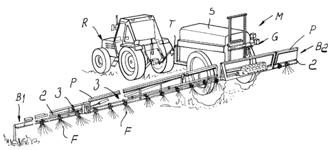
Figure 1 is a schematic perspective view of an agricultural spraying
machine provided with heads according to the invention;
Figure 2 is an enlarged-scale schematic view of a detail of the spraying
machine of Figure 1;
Figure 3 is a schematic perspective view of a head according to the
invention in which a nozzle is inserted;
Figure 4 is a schematic perspective view of the head of Figure 3 without
the nozzle;
Figure 5 is a schematic longitudinal sectional view of the head of Figure
3.
CA 02387202 2002-05-22
4
With reference to the figures, the reference numeral 1 generally
designates a universal head for fixing a nozzle to a fluid distribution duct,
particularly of the type for herbicidal, fungicidal, insecticidal treatments
or
the like, spread onto herbaceous or arboreal crops by spraying machines M.
The spraying machine M, of a conventional type, is substantially
constituted by a chassis T that supports a tank S for the fluid F that is
associated with a pumping assembly G that feeds two horizontal and
mutually opposite sprayer bars B1 and B2, which are designed to distribute
the fluid F on herbaceous crops.
io The spraying machine M is fixed to the rear of a tractor R, which travels
along the crop to be treated.
The bars B1 and B2 are constituted by a supporting frame P, which is
associated with the chassis T and to which tubes 2 for conveying the fluid F
are fixed; said tubes are fed by the assembly G, and adjustment and
distribution valves, control means and dispensing means 3 for the fluid F are
distributed along said tubes.
The dispensing means 3 are constituted by nozzle holders with one or
more outlets, five outlets in the illustrated case, each of which is
constituted
by a body 4 for connection and branching from the tubes 2, to which it is
coupled by means of a straddling coupling 5 that has an antidrip device 6.
A carousel 7 is rotatably associated with the body 4 and branches into
five selectively active distribution ducts 8, specifically 8a, 8b, 8c, 8d and
8e;
the rotation of the carousel 7 in fact connects to the tube 2 only the lower
duct 8a, excluding the remaining ducts 8.
The outlet of each duct 8 is rigidly coupled to a respective fluid
atomization nozzle 9 by means of a respective fixing head la, 1b, lc, ld and
le.
Depending on the treatment to be distributed, the model, shape and
dimensions of the nozzles 9 to be used may vary, but these characteristics of
the heads 1 do not. For the sake of simplicity, in Figure 2 the heads 1 are
CA 02387202 2002-05-22
shown rigidly coupled to the respective ducts 8 but without the nozzles 9.
Each head 1 is constituted by a cap-like sleeve 10, which is associated
with the outlet of the duct 8, to which it is rigidly coupled by way of
interlocking or threaded coupling means of a conventional type.
5 A slot 11 for inserting the nozzle 9 is formed at the top of the sleeve 10.
Proximate to the slot 11 locking means for locking the nozzle 9 are
provided which can expand radially and are constituted by two elastic
longitudinal and diametrically opposite wings 12, between which the nozzle
9 is inserted.
An annular base 13 is formed inside the sleeve 10 and at a lower part of
the slot 11, and the lower ends of the wings 12 are rigidly coupled thereto.
The upper ends of the wings 12 protrude freely outside the slot 11 and are
adapted to wrap around the nozzle 9 inserted therein and lock it.
Conveniently, between the inner edge of the slot 11 and the outer surface
of the wings 12 there is a play or gap 14 whose extent allows the outward
radial expansion of the wings 12 following the insertion of the nozzle 9.
Moreover, an annular surface 15 for the abutment of a retention collar 16,
formed at the lower base of the nozzle 9, is provided under the annular base
13 and inside the sleeve 10.
The reference numeral 17 designates two grip tabs, which are formed on
the outer surface of the sleeve 10 and are adapted to facilitate the assembly
and disassembly of the head 1 with respect to the duct 8, and the reference
numeral 18 designates the seat for a gasket for providing a seal to the fluid
F.
The means for coupling the head 1 to the duct 8 are constituted by a pair
of locking pins, not shown, which are provided so as to protrude and be
diametrically opposite on the outer lateral surface of the duct 8 and can be
inserted in corresponding slots 19 which are connected to locking grooves
20 formed at the base of the sleeve 10; the reference numeral 21 designates a
stop locator, which is adapted to prevent, by forming an obstacle, the
uncoupling of the head 1 from the duct 8.
CA 02387202 2002-05-22
6
The operation of the invention is as follows.
The outlets. of the ducts 8 are associated with respective nozzles 9,
optionally of different models, by using universal fixing heads 1, which are
mutually identical and independent of the nozzle models used.
Each nozzle 9 is inserted between the wings 12 of the respective head 1
until the collar 16 abuts against the annular surface 15; the upper ends of
the
wings 12, being of the elastic type, expand radially outward, adapting to the
shape of the nozzle 9 and locking it.
It is noted that in this manner the nozzle 9 is fixed stably between the
in wings 12 and no play remains between the coupled parts.
After inserting a gasket in the seat 18, the head 1 is rigidly coupled to a
duct 8, whose outlet is thus connected to the nozzle 9.
The carousel 7 allows to connect to the tube 2 the duct 8 on which the
nozzle 9 adapted to dispense the fluid F is mounted.
is In practice it has been found that the described invention achieves the
intended aim and objects, i.e., it provides a universal head for fixing a
nozzle
to a fluid distribution duct that allows to fix, in a simple and stable
manner,
any nozzle model among those known in the field.
The head according to the invention therefore allows to simplify
20 manufacturing cycles, to reduce reserves and to simplify inventory
management, and is immediately recognizable and usable by end users, who
no longer need to purchase a different head model for each nozzle model
they use.
The invention thus conceived is susceptible of numerous modifications
25 and variations, all of which are within the scope of the appended claims.
All the details may further be replaced with other technically equivalent
ones.
In practice, the materials used, as well as the shapes and the dimensions,
may be any according to requirements without thereby abandoning the
30 protective scope of the appended claims.