Note: Descriptions are shown in the official language in which they were submitted.
CA 02387227 2002-04-11
w n
~a
18916.2
Translation of PCT/EP00/09426 as filed on September 27, 2000
Brush, in Particular Tooth Bush
The invention concerns a brush, in particular a tooth brush,
comprising a brush body and a brush support supporting a
plurality of bristles and being preferably removably retained
on the brush body.
The invention is described below, by way of example, as a
tooth brush, however, it can be used in the same fashion with
other cleaning and application devices having bristles, in
particular, washing brushes, scrubbing brushes, cleaning
brushes, toilet brushes, brooms, paint brushes, application
brushes for creams, powder, cosmetics, medication, spices or
paint or even floor treatment brushes, wherein these
applications are explicitly included in the invention.
A manual tooth brush of conventional construction comprises a
longitudinal brush body made in general of plastic material,
whose rear section serves as a handle, and the front head end
of which comprises a bristle field having a plurality of
bristles fixed to the bristle body. An electrically driven
tooth brush has essentially similar construction, wherein the
brush body is subdivided into a base part accommodating the
driving motor and serving as handle, and an attachment part
supporting, at its front head, the bristle field and
CA 02387227 2002-04-11
w
. 2
comprising a transmission for converting the motion of an
output shaft of the driving motor into an oscillating or back
and forth rotating motion of the bristle field.
The bristle field of a tooth brush experiences the largest
amount of wear through use. Since worn or bent bristles
insufficiently clean the teeth and damage the gums, it is
recommended to replace tooth brushes every three months. With
conventional tooth brushes of this type, with the bristle
field being rigidly connected to the brush body, the bristle
body of manual tooth brushes must be entirely replaced when
the bristles are worn and the attachment part of electric
tooth brushes, including transmission, must be replaced. It
has been realized for some time that this procedure is both
uneconomical and ecologically questionable.
To prevent these problems, so-called removable head tooth
brushes have been developed, wherein the bristle field seats
on a removable bristle support, in particular in the form of
a stable plastic plate which engages in a depression in the
head of the brush body, limited by a projecting edge. Since
the dimensior_s of the tooth brush head are limited for
handling and application reasons, the edge of the depression
reduces the bristle field size. This limitation is acceptable
with manual tooth brushes. However, with electric tooth
brushes whose bristle field is in any event smaller than that
of manual tocth brushes for structural reasons, the bristle
field becomes very small which consequently reduces the
cleaning effect of the tooth brush.
CA 02387227 2002-04-11
3
Moreover, it has been shown that dirt and bacteria can
accumulate in the depression and in the gaps between the
bristle body and the brush support which are difficult to
remove such that use of some tooth brushes with removable
head is questionable with respect to hygiene.
To securely retain the removable bristle head on the brush
body, same has to be sufficiently stable and thus hard which
creates the problem that the sensitive mucous membranes come
in contact with relatively hard structural parts when using
the tooth brush. This could cause injuries.
In conventional tooth brushes, the bristles are usually
rigidly held in the bristle support. This has the
disadvantage that the bristles cannot deflect in the axial
direction during cleaning and can deflect in a transverse
direction only due to their intrinsic flexibility. When
applying large cleaning forces, these forces transferred to
the teeth and gums essentially without resilient absorption
thereby possibly causing injuries. It has been attempted to
dispose the bristle bundles in a resilient fashion on the
brush support. However, the construction required therefor is
very demanding and requires very expensive production
methods.
It is the underlying purpose of the invention to produce a
brush of the mentioned type which avoids the above-mentioned
problems and which is of simple construction.
f
CA 02387227 2002-04-11
4
This object is achieved in accordance with the invention in a
brush of the mentioned type in that the bristle support,
consisting of soft-elastic plastic material, is formed like a
cap and can be drawn over a projection of the bristle body.
In accordance with the invention, the bristle support bearing
the bristle field is formed as a flexible cap e.g. of an
elastomeric plastic material which can be drawn, like a
cover, onto a projection, in particular, on the brush body
head such that it surrounds and covers the projection and is
securely held on the projection by tensioning forces
resulting in particular from the elastic deformation of the
cap, however, can be removed from same when required. The
tensioning or retaining forces of the cap-like bristle
support are thereby determined by its ability to deform which
depends on its geometric design, its wall thickness and the
elastic properties of its material.
The inventive cap-like bristle support is drawn over the
projection and in particular the head of the bristle support
and is not inserted therein, which has the essential
advantage that the surface of the bristle support is larger
than the surface of the projection overlapping it, such that
the bristle field can be relatively large.
The soft-elastic and thus very flexible plastic material of
the cap-like bristle support can be easily deformed in all
directions such that the bristles can resiliently deflect in
CA 02387227 2002-04-11
their axial direction and also perpendicular thereto when
cleaning forces are applied.
The cap-like bristle support is held on the projection of the
brush support by tensioning forces resulting from its elastic
deformation thereby preventing formation of gaps between the
bristle support and the brush body and accumulation of dirt
and resulting formation of bacteria.
The cap-like bristle support covering the projection of the
brush body serves at the same time as mucous membrane
protection due to its soft-elastic material and has the
further advantage that the constructional height of the brush
is small.
A preferred embodiment of the invention provides that the
brush support comprises an upper, preferably diaphragm-like
covering part having bristles on its upper side and
supporting, on its lower side facing away from the bristles,
a preferably continuous and peripheral flexible projecting
edge or bridge mounted onto the covering part or formed in
one piece therewith. The height of the bridge may be constant
or also vary along the circumference. In the mounted state of
the cap-like bristle support, the projection of the brush
body is disposed below the covering part and between the
peripheral bridge which is tensioned on the projection from
the outside. Alternatively or additionally, a bridge may be
provided which abuts from the inside on a recess wall in the
brush body.
CA 02387227 2002-04-11
6
The bristles are disposed at least in partial areas of the
upper side of the covering part whose whole surface is
preferably provided with bristles. Additionally or
alternatively, the bristles may be disposed at least in
partial areas of the outer side of the bridge tensioned
against the projection from the outside.
In a possible embodiment, the covering part of the cap-like
bristle support may extend essentially level. The covering
part may also have a spatial structure, at least in the
mounted state. This can be achieved by providing the upper
side of the projection of the brush body with a structured
surface and disposing the flexible covering part of the
bristle support onto the structured upper side of the
projection such that it abuts and follows said structure.
Therein, the spatial course of the covering part in the
mounted state is determined by the surface structure of the
projection of the brush body. Alternatively, it is also
possible to provide the covering part itself with a
structured surface which can be effected either during the
production process, e.g. during injection-molding or
injection of the bristles or by subsequent deformation, in
particular compressing or deep-drawing of the initially flat
covering part.
All embodiments may additionally be provided with bristles
having differing bristle lengths and/or bristle orientations
forming a topographic structure with different heights.
CA 02387227 2002-04-11
7
A further preferred design of the inventive brush provides at
least one cavity below and/or within the cap-like bristle
support. This cavity can provide the covering part supporting
the bristles with elastic resilience, wherein the resilience
is determined by the shape of the cavity and can be adjusted
as desired by a damping fluid to be filled into the cavity.
Alternatively, the cavity can be used to accommodate a medium
to be applied during use of the brush. The medium may either
be fluid or powdery cosmetics, tooth care products etc..
Supply and application of the medium can be effected e.g.
through openings in the flexible cap-like bristle support,
hollow bristles or bristle bundles or through the capillary
effect of bristle bundles.
In a simple embodiment of the cavity, the cap-like bristle
support can be disposed onto the projection in such a fashion
that an intermediate space forming said cavity is generated
between the lower side of the covering part of the bristle
support and the upper side of the projection such that the
cavity is limited by the bristle support and the brush body.
A preferred further development of the invention provides
that a dividing wall divides the cavity into separate
chambers which preferably contain media having different
characteristics which are mixed and react with one another,
optionally, not before leaving the respective chamber.
Moreover, the cavity may contain an agent which reacts with
CA 02387227 2002-04-11
v
_ . 8
an externally applied tooth paste or cleaning cream thereby
forming an optimized agent for the intended purpose.
The amount of the medium leaving the cavity or the chambers
depends on the deformation of the cavity and in particular of
the covering part limiting same.
The cavity or the chambers may be provided with a foamed
insert which is inserted either as separate pre-fabricated
part or injection-molded in a multiple-component injection-
molding process during production of the cap-like bristle
support or introduced by foam mold. The foamed insert serves
as a damping member for deformation of the covering part
supporting the bristles. Moreover, the insert may also be
soaked with a medium to be applied. The use of hydrophilic
foam allows storage of liquid or gaseous media, contained by
said foam, in the cavity. Such enriched foams are easy to
handle and, in particular, can be exchanged.
The cavity can be associated with a storage region connected
therewith containing a medium to be applied which is
supplied, through a passage, to the cavity containing a
foamed or sponge insert for throttled and uniformly dosed
supply of the medium to the bristle field.
The design of a cavity can also be effected or improved when
at least sections of the brush body are formed as cups and
the cap-like bristle support traverses the cup-like area like
a cover. If the brush body as a whole is formed like a cup
CA 02387227 2002-04-11
~ 9
and is traversed and covered by the cap-like bristle support,
formation of a very flat brush with an inner cavity is
possible which can be filled with a medium to be applied or
also charged with cartridges, tablets, filled foamed or
sponge inserts.
The resilience of the bristle field is determined essentially
by the thickness of the diaphragm-like covering part. The
deformation possibilities increase with reduced thickness of
the covering part. With electrically operated tooth brushes,
a covering part thickness in the range between 0.5 and 3.0 mm
has been shown to be reasonable. This has the essential
advantage that the overall height of the brush is very low.
Deformation of the cap-like bristle support and in particular
of the covering part can be further adjusted by forming
projections and/or recesses on the inner side of the bristle
support and in particular of the covering part. The
projections form reinforcements which impair deformation
whereas the recesses define areas which are particularly soft
for deformation.
To prevent excessive deformation of the bristle support
during use and also guarantee that the bristle support
returns into its initial position without load, the inner
side of the bristle support may be provided with at least one
spring element supported on the brush body. During use, the
covering part is deformed against the resilient force of the
spring element which, when unloaded, returns the covering
part into its initial position. The spring element may
w
CA 02387227 2002-04-11
- '~ 10
preferably be formed by a shackle or bridge fashioned on the
lower side of the covering part.
In order to be able to also properly clean inclined surfaces,
tilting of the bristle field relative to the brush body is
advantageously possible. This can be easily achieved when the
bridge is flexible in an axial direction i.e. essentially
perpendicular to the covering part and the bristle field.
Since the specific elasticity of the bridge is limited, the
axial flexibility of the bridge can be assisted when at least
sections thereof are formed as bellows.
The bridge, extending on the outside of the projection of the
brush body, moreover serves as a protective coating and in
particular as mucous membrane protection for the user.
Elements may be additionally integrated in the bridge which
provide impact protection and which resiliently yield with
contact. This can be achieved e.g. in that the bridge
comprises elastically deformable projections on its outer
peripheral surface which may have the shape of a ring, a loop
or a punched tape.
A possible embodiment may provide that the bridge extends in
the edge area of the covering part. In an alternative, the
covering part may project laterally i.e. radially beyond the
bridge thereby forming a freely protruding edge projection.
These freely protruding edge sections may be particularly
flexible and thus contribute to protective mucous membrane
massage. If, during use, a correspondingly equipped brush
r CA 02387227 2002-04-11
' 11
meets an inclined surface area, the edge section bends
relative to the covering part such that the inclined surface
area is cleaned simultaneously on both abutting surfaces.
Normally, the tensioning and frictional forces resulting from
elastic deformation of the cap-like bristle support are
sufficient for retaining same securely on the projection of
the brush body. It is possible to provide special engagement
means for fixing the bristle support on the brush body in a
non-rotatable fashion. Special engagement means may also be
provided to which the bristle support is fixed on the brush
body in a non-rotatable fashion in the form of e.g. sealing
projections provided on the inside of the bridge which engage
in corresponding recesses of the brush body thereby providing
fixation in a non-rotatable and/or non-lifting fashion.
Alternatively, the sealing projections may also be formed on
the brush body and the recesses may be formed on the bridge.
The dimensions of the cap-like bristle support are adjusted
to the respective application. A relatively flat cap may be
provided having a covering part with short bridges. However,
it is also possible to design the cap-like bristle support
like a stocking, i.e. for forming a longitudinal cylinder
with relatively long bridges as is e.g. required for forming
an interdental brush or individual rotating bristle bundles.
The bristles may be pre-fabricated and mounted to the bristle
support in a conventional fashion. Alternatively, it is also
possible to form the bristles in one piece with the bristle
CA 02387227 2002-04-11
12
support and in particular to injection-mold them together
using a one-component or two-component method. It is possible
to form bristles of different shape, different materials and
different orientation on the bristle support.
When the cap-like bristle support has a cavity, the pressure
increase occurring during deformation of the flexible bristle
support in the cavity can be utilized for actuating an
indicator element. The indicator element can e.g. be a
displaceably disposed piston which is pushed outwardly when
the cavity increases and is retracted into its initial
position when the deformed bristle support is returned,
thereby producing an indication of the pressing force which
the user applies to the bristles. Alternatively or
additionally, the medium contained in the cavity could change
color under pressure to thereby also represent a pressure
indication.
The pressure increase in the cavity may also open an outlet
valve for a medium to be applied which is contained in the
cavity, thereby ensuring that the medium can exit the cavity
only upon application of a corresponding pressure by the
user.
Deformation of the flexible bristle support can be used
directly for adjusting an actuating element in that the
displacement of partial areas of the wall of the cap-like
bristle support occurring during deformation is converted
directly into adjustment of a mechanical indicator.
CA 02387227 2002-04-11
13
Further details and features of the invention can be
extracted from the following description of embodiments with
reference to the drawing.
Fig. 1 shows a representation of the front end of a
tooth brush with attached cap-like bristle
support;
Fig. 2 shows a sectional view of a bristle support;
Fig. 3 shows a sectional view of an alternative
embodiment of a brush with attached bristle
support;
Fig. 4 shows a modification of the embodiment in
accordance with Fig. 3;
Fig. 5 shows a sectional view of a further
alternative embodiment of a brush with
attached bristle support;
Fig. 6 shows a modification of the embodiment in
accordance with Fig. 5;
Fig. 7 shows a modification of the embodiment in
accordance with Fig. 6;
CA 02387227 2002-04-11
~ 14
Fig. 8 shows a modification of the bristle support
in accordance with Fig. 2;
Fig. 9 shows a sectional view of a bristle support
with a modified geometrical shape;
Fig. 10 shows a sectional view of the bristle support
with reinforcement;
Fig. 11 shows a sectional view of a bristle support
with a recess;
Fig. 12 shows a sectional view of a bristle support
with spring element;
Fig. 13 shows a sectional view of a bristle support
with an alternative spring element;
Fig. 14 shows a sectional view of a bristle support
with a deformable bridge;
Fig. 15 shows a sectional view of a bristle support
with lateral protection elements;
Fig. 16 shows a view from below of the bristle
support in accordance with Fig. 15;
Fig. 17 shows a further alternative embodiment of the
bristle support in accordance with Fig. 2;
CA 02387227 2002-04-11
, 15
Fig. 18 shows a modification of the bristle support
in accordance with Fig. 17;
Fig. 19 shows a further alternative embodiment of the
bristle support in accordance with Fig. 2;
Fig. 20 shows a modification of the bristle support
in accordance with Fig. 19;
Fig. 21 shows a view from below of a bristle support
with non-rotational fixation;
Fig. 22 shows a view from below of a bristle support
with alternative embodiment of the non-
rotating fixation;
Fig. 23 shows a sectional view of a stocking-shaped
bristle support;
Fig. 24 shows a sectional view of a bristle support
with engagement fixation;
Fig. 25 shows a sectional view of an alternative of a
bristle support with engagement fixation;
Fig. 26 shows a bristle support on a plate-shaped
projection;
CA 02387227 2002-04-11
~ 16
Fig. 27 shows a sectional view of a bristle support
of several components;
Fig. 28 shows a sectional view of a bristle support
of several structural parts;
Fig. 29 shows a sectional view of a brush with cap-
shaped bristle body;
Fig. 30 shows a sectional view of a bristle support
with cavity;
Fig. 31 shows a sectional view of a bristle support
with cavity and storage region;
Fig. 32 shows a horizontal section through a bristle
support comprising a multiple chamber cavity;
Fig. 33 shows a sectional view of a bristle support
with injection-molded bristles;
Fig. 34 shows a sectional representation of a
bristle support with indicator element;
rFig. 35 shows an alternative embodiment of the
bristle support in accordance with Fig. 34;
CA 02387227 2002-04-11
- ~' 17
Figs.36a and 36b show a sectional representation of a bristle
support with alternative indicator element in
two functional states;
Figs.37a and 37b show a sectional representation of a bristle
support with an alternative indicator element
in two functional states;
Figs.38a and 38b show a sectional representation of a bristle
support with an alternative indicator element
in two functional states;
Figs.39a and 39b show a sectional representation of a bristle
support with an alternative indicator element
in two functional states;
Fig. 40 shows a sectional view of a brush body with
two attached bristle supports;
Fig. 41 shows a further development of the embodiment
in accordance with Fig. 40; and
Figs.42a and 42b show a sectional representation of a bristle
support with a valve in two functional
states.
Fig. 1 shows the front part of a tooth brush 10 with a brush
body 11 serving as handle comprising, at its front end, a
block-like projection lla serving as support. A flexible cap-
.- CA 02387227 2002-04-11
- ' 18
like bristle support 13 is drawn over the projection lla and
supports a plurality of bristles 12 on its upper side. Fig. 2
shows that the bristle support 13 comprises a flat diaphragm-
like covering part 13a which supports the bristles 12 on its
upper side and comprises, in the edge area on its lower side
facing away from the bristles 12, a peripheral bridge 13
projecting do~anwardly. The inner dimensions of the bristle
support 13 are somewhat smaller than the outer dimensions of
the projection lla such that it can be attached to the
projection lla under elastic deformation without play. Due to
the elastic deformation, the peripheral bridge 13b of the
bristle support 13 stretches over the projection lla from the
outside and is securely held thereon.
The bristles 12 may extend parallel or at an angle to one
another, wherein in the latter case, they project laterally
over the bristle support thereby increasing the work surface.
Alternatively, it is also possible to bend the bristles
individually and/or orient them in different directions or
crosswise.
While the projection lla represented in Fig. 1 comprises an
essentially rorizontal surface on which the covering part 13a
of the bristle support 13 is level, in Fig. 3 the surface of
the projecticn 11a is convex which gives the covering part
13a of the drawn-over bristle support 13 a likewise convex
shape.
CA 02387227 2002-04-11
19
In accordance with the embodiment of figure 4, the covering
part 13a also follows the surface structure of the projection
lla which is wavy in the present case.
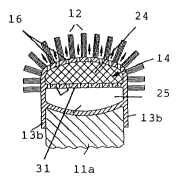
In accordance with figure 5, the covering part 13a of the
bristle support 13 has a convex shape and is disposed at a
separation from the surface of the projection lla thereby
forming a cavity 14 between the bristle support 13 and the
projection 11. Upon exertion of external pressure onto the
bristles 12, the bristle support 13 may resiliently yield
towards the inside, whereby the fluid contained in the cavity
14, e.g. air, damps deformation of the bristle support 13. In
a further development in accordance with figure 6, a foamed
body 15 can be introduced into the cavity 14 whose specific
elasticity damps deformation of the bristle support 13. The
foamed body 15 may be filled with a liquid or gaseous medium
to be applied, wherein the medium may exit through passages
16 (figure 7) formed in the covering part 13a of the bristle
support 13.
In the previous embodiments, the bristle support 13 is
provided with bristles on the upper side of the covering part
13a only. Figure 8 shows an embodiment wherein the outer
surface of the bridge 13b has also bristles 12. Therein, the
bridge 13b for forming a longitudinal stocking-shaped hollow
body may be relatively long (figure 9).
The bristles 12 may be disposed over the entire surface of
the outer side of the bristle support 13 or only on partial
- CA 02387227 2002-04-11
' 20
areas thereof. Moreover, the bristles may have identical or
different lengths and form, with their tip sections, a
covering surface of any topographic shape.
In the embodiment of the bristle support 13 shown in figure
10, a projection 18 serving as reinforcement is formed on the
lower side of the covering part 13a by means of which the
deformation characteristics of the covering part 13a change
with external load and can be adjusted to the desired
application. While the projection 18 increases the rigidity
of the covering part 13a, the covering part 13a may also
alternatively comprise recesses 19 which reduce the rigidity
of the covering part (Fig. 11).
In accordance with figures 12 and 13, spring elements 20 are
provided or formed on the lower side of the covering part 13a
which are supported on the upper side of the projection 11a.
The spring elements 20 are compressed during external loading
of the covering part 13a and guarantee that the covering part
is forced back into its initial position after de-loading. In
accordance with figure 12, the spring element 20 is formed by
a strap-like shackle held at both ends on the covering part
13a. In figure 13, a double S-shaped support is provided as
spring element which is mounted on its upper end to the
covering part 13 and is supported with its lower end on the
projection 11a.
In accordanc? with figure 14, the bridge 13b of the bristle
support 13 is formed sectionally as bellows 21 thereby
-- CA 02387227 2002-04-11
' 21
enabling tilting of the covering part 13a, having the
bristles 12, relative to the projection lla during use
without the danger that the bristle support 13 slides off
from the projection 11a. This provides good, resilient
support of the bristles, even on an inclined cleaning
surface .
The bridge 13b abutting the side surface of the projection 11
in the mounted state also serves as a protective coating and,
in particular in a tooth brush, as mucous membrane
protection. Figures 15 and 16 additionally provide that the
bridge 13b comprises, on its outer peripheral surface,
elastically deformable projections 22 which are formed by
sectionally wavy configuration of the bridge 13b in
accordance with figure 16.
Figures 17 and 18 show two embodiments wherein the covering
part 13a projects laterally or radially outwardly over the
bridge 13b thereby forming a freely protruding edge section
13c. In this fashion, the work surface provided with bristles
12 is increased and, due to the flexibility of the freely
protruding edge section 13c, they can easily abut on and
clean a curved or angled surface. Fig. 18 shows a further
development, wherein the outer sections of the freely
protruding edge sections 13c are bent downwardly thereby
forming an outwardly curved, convex section.
The deformability of the bristle support 13 is determined
i.a. by its geometric design. To provide the peripheral
_. CA 02387227 2002-04-11
' 22
bridge 13b, which essentially has a holding function, with
sufficient stability and to simultaneously allow easy
deformation of the covering part 13a, these two sections may
have different wall thicknesses, as shown in Fig. 19.
Therein, the slightly stronger bridge 13b continuously passes
over into the relatively thin covering part 13a. To prevent
excessive deformation in the central region of the covering
part 13a, this area may have a larger wall thickness, e.g. a
reinforcement 18 as represented in figure 20.
To retain the bristle support 13 on the projection 11a in a
non-rotatable fashion, the inner side of the bridge 13b is
provided with a single recess 30 (shown in figure 21), which
can engage with a correspondingly formed nose (not shown) of
the projection 11a. Alternatively and in accordance with
figure 22, the inner peripheral surface of the bridge.l3b may
be polygonal and, in particular, in accordance with the
figure, octagonal and disposed on a corresponding polygonal
projection.
Fig. 23 shows the bristle support 13 as a longitudinal
stocking-shaped cylinder with a relatively small covering
part 13b supporting bristles on its upper side configured in
the shape of a triangle. Such a bristle support may be used
as a bristled cap for interdental brushes or as a removable
cap for electric tooth brushes having individual rotating
bristle bundles.
CA 02387227 2002-04-11
- ' 23
To secure the cap-shaped bristle support 13 on the projection
11a, the inner side of the bridge 13b, in the embodiment in
accordance with figure 24, comprises a peripheral inward
facing engagement nose 23 which can engage in a
correspondingly formed recess of the projection 11a. In
accordance with figure 25, the upper section llal of the
projection lla is bulged to the outside and is undercut by
the bridge 13b of the flexible bristle support 13. In a
further embodiment in accordance with figure 26, the
projection lla is formed as a plate and is undercut by the
bridge 13b of the attached cap-like bristle support 13.
The bristle support 13 can be made from one single material.
However, figures 27 and 28 show that the covering part 13a
and the bridge 13b can be produced from different flexible
plastic materials, in particular via a two-component
injection-molding process. In this fashion, the material
properties of the individual areas can be well adapted to
their required function during use. Alternatively (fig. 28),
the covering part 13a and the bridge 13b may be pre-
fabricated and connected to one another later by welding,
gluing, clamping or in any other manner.
As mentioned above, a cavity 14 may be formed between the
projection lla of the brush body 11 and the cap-like bristle
support 13. Formation of the cavity 14 is facilitated when
sections of the projection lla of the brush body 11 are cap-
shaped or when it is entirely formed like a cap, as shown in
CA 02387227 2002-04-11
t
" 24
figure 29. A foamed insert is thereby inserted in the cavity
14 .
Fig. 30 shows an embodiment wherein a further dividing wall
13d extends between the inner wall of the bridge 13b of the
bristle support 13 below the covering part 13a such that the
cavity 14 is formed within the bristle support 13 between the
upper covering part 13a and the lower dividing wall 13d. The
further development shown in figure 31 is provided with a
storage region 25 for a medium to be applied which is located
below the cavity 14 in which a foamed insert 24 is disposed.
The cavity 14 is separated from the storage region 25 by a
dividing wall 31 provided with passages 26. The medium may
flow from the storage region 25 through the passages 26 into
the foamed insert 24 of the cavity 14 and is delivered
therefrom to the bristles 12 via passages 16 in the upper
covering part 13a.
As shown in figure 32, the cavity 14 may be subdivided by
inner dividing walls 32 into several separate chambers 14a,
14b, 14c which can accommodate various media which flow
together and react following exit.
Fig. 33 shows an embodiment. The bristles are not pre-
fabricated by a spinning method and then mounted to the
bristle support, rather are produced in one piece therewith
using a one-or two-component injection-molding process.
f
CA 02387227 2002-04-11
- ' 25
Figures 34 to 39b show various embodiments wherein the load-
related pressure increase in the cavity 14 occurring during
deformation of the bristle support 13 is indicated by an
indicator. In accordance with figure 34 a displaceable piston
27 is disposed in a connection piece-shaped section 13e of
the bridge 13b of the bristle support 13. When the user
presses from the outside on the bristles 12 or the covering
part 13a (arrow D), the volume of the cavity 14 is reduced
and the inner pressure increases thereby pushing the piston
27 outwardly as indicated by arrow S in figure 34. The user
can observe the pushed-out piston. The degree of displacement
of the piston 27 indicates the inner pressure of the cavity
14 and thus the external pressure applied by the user. The
displacement of the piston 27 can also serve for triggering
further mechanical, acoustical and/or electrical signals.
In accordance with figure 35, a support acting as spring 20
is formed on the lower side of the covering part 13a and is
supported on the upper side of the projection 11a. Also in
this case, a piston 27 is displaceably disposed in a passage
of the bridge 13b which abuts with its inner end on the
spring 20. If the user presses from the outside onto the
bristles 12 or the covering part 13a (arrow D), the spring 20
is laterally deflected thereby outwardly displacing the
piston 27, as shown by arrow S.
In accordance with figure 36a, a thin-walled closing
diaphragm 28 is formed on the outer side of a pipe socket-
shaped passage 36 formed in the bridge 13b which, with
CA 02387227 2002-04-11
26
increasing inner pressure, can be blown up like a balloon, as
indicated in figure 36b, thereby providing an indication of
the pressure applied by the user onto the bristles (arrow D).
In accordance with figures 37a and 37b, a passage 37 is
directly formed in the wall of the bridge 13b and sealed by a
closing diaphragm 28 which can be expanded and - as shown in
figure 38b - bulges outwardly with increased inner pressure
in the cavity 14. Therein, the closing diaphragm 28 may be
pre-fabricated as a separate structural part and then mounted
in the passage 37. It is, however, also possible to
injection-mold the closing diaphragm 28 on the bridge 13b, in
one piece.
A similar closing diaphragm 28 may be formed in a passage 34
of a lid 33 closing the lower side of the bristle support 13
(figure 38a) which curves downwardly with increased inner
pressure (figure 38b) .
In accordance with the embodiment of figures 39a and 39b, an
indicator bar 29 is displaceably guided in the lid 33 and is
formed, at its upper end, on the covering part 13a. When the
covering part 13a is downwardly deformed by application of
external pressure, the indictor bar 29 is pushed downwardly
out of the lid 33 (Fig. 39b) and can be directly used as a
pressure indicator or, as described above, for triggering a
corresponding signal.
CA 02387227 2002-04-11
~ 27
Fig. 40 shows an embodiment with which one cap-like bristle
support 13 is disposed on each of two different sides of a
projection lla of a brush body 11. If the inner space of the
projection lla in accordance with figure 41 is divided by a
dividing wall 11a2 into two separate chambers, different
media can be disposed therein to each be associated with one
specific bristle support 13, such that the user can select
the one or other medium depending on the orientation of the
brush.
In accordance with the embodiment shown in figures 42a and
42b, a passage 16 is provided in the covering part 13a which
can be closed or opened by means of an adjustable valve
element 35. The valve element 35 is disposed on the lower
side of the covering part 13a via a strap formed thereon as a
single piece and can be adjusted between the closing and
opening position under elastic deformation of the strap 34.